US2544061A - Speed change driving head for power-driven machines - Google Patents
Speed change driving head for power-driven machines Download PDFInfo
- Publication number
- US2544061A US2544061A US48985A US4898548A US2544061A US 2544061 A US2544061 A US 2544061A US 48985 A US48985 A US 48985A US 4898548 A US4898548 A US 4898548A US 2544061 A US2544061 A US 2544061A
- Authority
- US
- United States
- Prior art keywords
- pin
- head
- casing
- sleeve
- speed change
- Prior art date
- Legal status (The legal status is an assumption and is not a legal conclusion. Google has not performed a legal analysis and makes no representation as to the accuracy of the status listed.)
- Expired - Lifetime
Links
- 239000003921 oil Substances 0.000 description 8
- 230000002093 peripheral effect Effects 0.000 description 4
- 238000007789 sealing Methods 0.000 description 3
- BSYNRYMUTXBXSQ-UHFFFAOYSA-N Aspirin Chemical compound CC(=O)OC1=CC=CC=C1C(O)=O BSYNRYMUTXBXSQ-UHFFFAOYSA-N 0.000 description 1
- 238000010276 construction Methods 0.000 description 1
- AAOVKJBEBIDNHE-UHFFFAOYSA-N diazepam Chemical compound N=1CC(=O)N(C)C2=CC=C(Cl)C=C2C=1C1=CC=CC=C1 AAOVKJBEBIDNHE-UHFFFAOYSA-N 0.000 description 1
- 239000000295 fuel oil Substances 0.000 description 1
- 239000000463 material Substances 0.000 description 1
- 230000000452 restraining effect Effects 0.000 description 1
- 230000035939 shock Effects 0.000 description 1
- 238000006467 substitution reaction Methods 0.000 description 1
Images

Classifications
-
- F—MECHANICAL ENGINEERING; LIGHTING; HEATING; WEAPONS; BLASTING
- F16—ENGINEERING ELEMENTS AND UNITS; GENERAL MEASURES FOR PRODUCING AND MAINTAINING EFFECTIVE FUNCTIONING OF MACHINES OR INSTALLATIONS; THERMAL INSULATION IN GENERAL
- F16H—GEARING
- F16H37/00—Combinations of mechanical gearings, not provided for in groups F16H1/00 - F16H35/00
- F16H37/02—Combinations of mechanical gearings, not provided for in groups F16H1/00 - F16H35/00 comprising essentially only toothed or friction gearings
- F16H37/06—Combinations of mechanical gearings, not provided for in groups F16H1/00 - F16H35/00 comprising essentially only toothed or friction gearings with a plurality of driving or driven shafts; with arrangements for dividing torque between two or more intermediate shafts
- F16H37/08—Combinations of mechanical gearings, not provided for in groups F16H1/00 - F16H35/00 comprising essentially only toothed or friction gearings with a plurality of driving or driven shafts; with arrangements for dividing torque between two or more intermediate shafts with differential gearing
- F16H37/0833—Combinations of mechanical gearings, not provided for in groups F16H1/00 - F16H35/00 comprising essentially only toothed or friction gearings with a plurality of driving or driven shafts; with arrangements for dividing torque between two or more intermediate shafts with differential gearing with arrangements for dividing torque between two or more intermediate shafts, i.e. with two or more internal power paths
- F16H37/084—Combinations of mechanical gearings, not provided for in groups F16H1/00 - F16H35/00 comprising essentially only toothed or friction gearings with a plurality of driving or driven shafts; with arrangements for dividing torque between two or more intermediate shafts with differential gearing with arrangements for dividing torque between two or more intermediate shafts, i.e. with two or more internal power paths at least one power path being a continuously variable transmission, i.e. CVT
- F16H37/0846—CVT using endless flexible members
Definitions
- This invention relates to. speed change driving.
- One of. the objects .of my invention is to provide a drillpress withia. head having mechanism for varying v the speed @of the .drill .spindlecontained therein and operativeasaunit;
- Another object is to provide a drill press having. a-speed .change unit. surrounding the. spindle, arranged tovarythetspindle speed, with reference tothatofthe drivir'ig. motor, throughouta wide range, without the necessity of changing beltsor shifting pulleys;
- Another object is to provide a speed change mechanism for drill presses or other power driven tools which is cheaply. andeasily constructed, and extremely easy to operate
- Another object'is to. provide a driving head for power driven machinery having a spindle drive including a combined'variable speed pulley and planetary speed change gearing; i
- a still further object is to provide a speed vary ing drill press head, as above mentioned, with an oiling system which automatically circulatesoil within said. head throughout the gearing andwear' surfaces therein whenever the'gearporti'onof the.
- Sleeve 4 has an integrally. formedfiange l2 extending outward from its .middlporticin. which.
- A" cup-shapedhousing, E6 is journalled on the lower part ofsie'eve 4 below flange support [2V ally positioned h'ole 32 'in gear housing l6. It isv normally urged upward by asprin 33 set inthe undergroove of head 3
- a forkisfi is secured in a channel 31in head frame plate 2! so that it may be operated inand out. radially. relative. to the spindle axis.
- the drivirigelement has a double flanged pulley for'v belt 56 withone stationary flange 5! and the other flange-52" held resiliently toward the stationaryfiange hysprings Variation of the tension ofthe belt'willalterthe effective radial above described, I provide an annularoil groove so formed in the lower face of driving element 7.
- Casing I6 is sealed at the bottom by sealed ball bearing 62 and around its upper rim by a ring 63 of soft rubber like material set into an annular groove in the upper edge of the casing and having an inwardly extending lip 6
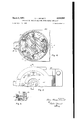
- Arcuate slots 64 cut through plate l2 near its hub have end walls 65 slanting downwardly and outwardly in each direction. These slots enable oil forced outward and downward from the space 8i), and from the space above idler gears Hi, to escape upward from space 68 between the bottom of the ring gear housing and the lower face of plate 12. The rotation of this plate and its radially extending lobes forces this oil outward to the rim H of the housing I6. The forcing of the oil outwardly creates a zone of low pressure at the inner annuli above slots E i, and a zone of higher pressure at the peripheral area. This differential pressure forces the oil at the peripheral area downwardly and inwardly through space 68, and thence upwardly through arcuate holes 64. All the interior cup-like space of housing 56 is filled with heavy oil through filling hole 89 ( Figure 6).
- the spindle or shaft 2 is keyed to and driven by the sleeve 4.
- This sleeve may be driven either directly by the driving element l or indirectly through the planetary gearing composed of the sun gear l9, idler gears I l and ring gear ii, at a reduced speed. In either case the speed of the driving element i may be varied by changing the tension of the belt running over pulley 8.
- the sleeve 4 is rigidly supported and journalled in the head frame of the drill press by bearings 26 and 29.
- the spindle may be independently journalled in such other and suitable bearings as may be necessary to maintain it in alinement.
- drive head here illustrated and described is particularly adapted for use on drill presses, but it is at once obvious that spindle 2 can be replaced by any other shaft desired to be driven to operate other light shop machinery. In all cases a high and low speed is made available by shifting from direct to gear driven speed, and intermediate speeds are obtained by varying belt tension on pulley 8. Thus the drive head is a unit which is both compact and sturdy and is extremely easy to operate.
- a speed change driving unit for drill presses or the like comprising a driven spindle, a driving sleeve having a flange with radially extending lobes forming detaining notches therebetween splined on said spindle, a driving element having a variable speed V belt pulley at its top and a sun gear at its bottom journalled on said sleeve above said flange, a casing having an annular rim at its top with a ring gear on the inner face thereof, journalled on said sleeve below said flange, planetary idler gears journalled on stub shafts on said flange lobes parallel to said spindle, meshing with said sun gear and said ring gear, support frame bearings journalled at each end of said spindle, one of said bearings being adjacent said casing and having a radially extending slide, a pin engaging fork having tines beveled on their bottom faces at its inner end operative in said slide, means for de
- a speed change head for drill presses having a sleeve with a flange carrying idler planetary gears, a drive element having a sun gear meshing with said idler gears and a peripheral portion adapted to contact a resilient sealing ring, a casing having an upturned rim carrying a ring gear meshing with said idler gears, an oiling system including an annular oil retaining cavity formed on the bottom face of said drive element above said sun gear having a filling hole opening through the upper part of said drive element, a cup-shaped cavity formed in the upper face of said casing to receive said flange and idler gears and, retain oil to immerse said gearing, a sealing bearing between said casing and said sleeve, a resilient sealing ring between the upper edge of said casing and said peripheral portion of said drive element, arcuate openings having a trapezoidal elevation formed in said flange adjacent said spindle connecting said oil retaining cavity in said casing with the area above said flange adjacent said oil
- a speed change head for power driven machinery including a supporting frame, having bearings journaling a sleeve, a driving element having a sun gear journaled on said sleeve, a driven spindle shaft keyed to said sleeve, a cylindrical casing journaled on said sleeve having a cup shaped recess on its upper face provided with an internal ring gear, said sleeve having a flange midpositioned relative to its length with radially extending lobes thereon and detaining notches therebetween; and planetary idler gears operative on said lobes between said sun gear and said ring gear; in combination therewith, mechanism for shifting from direct drive to planetary gear drive, including a detaining pin slidably operative in a radially positioned hole in said casing having an undercut upper head adapted to engage in said detaining notches when in raised position, rubber inserts on the contacting faces of said notches, a spring
Landscapes
- Engineering & Computer Science (AREA)
- General Engineering & Computer Science (AREA)
- Mechanical Engineering (AREA)
- General Details Of Gearings (AREA)
Description
March 6, 1951 SPEED CHANGE Filed Sept. 13, 1948 E. T. BARNETT 2,544,061
DRIVING HEAD FOR POWER-DRIVEN MACHINES 3 Sheets-Sheet l INVENTOR.
March 6, 1951 E. T. BARNETT SPEED CHANGE DRIVING HEAD FOR POWER-DRIVEN MACHINES 3 Sheets-Sheet 2 Filed Sept. 15, 1948 JNVENTR.
March 6, 1951 E. T. BARNETT 2,544,061
SPEED CHANGE DRIVING HEAD FOR POWER-DRIVEN MACHINES Filed Sept. 15, 1948 5 Sheets-Sheet 3' Patented Mar. 6, 1951 SPEEUCHANGE DRIVING. HEAD FOR 9 POWER-.eDRIV EN :MACHIN'ES Elson Thomas.Barnett, Phoenix, Aria, assignor. V to Savage-Barnett 'li'ool Company, Phoenix, Aria, a corporation of Arizona" Application September 13, 1948; Serial NoAEhQSd (Cl. I l -785) 3 "Claims.
This inventionrelates to. speed change driving.
heads .for power. driven machines, such as drill. presses and thelike.
One of. the objects .of my invention is to provide a drillpress withia. head having mechanism for varying v the speed @of the .drill .spindlecontained therein and operativeasaunit;
Another object is to providea drill press having. a-speed .change unit. surrounding the. spindle, arranged tovarythetspindle speed, with reference tothatofthe drivir'ig. motor, throughouta wide range, without the necessity of changing beltsor shifting pulleys;
Another object is to providea speed change mechanism for drill presses or other power driven tools which is cheaply. andeasily constructed, and extremely easy to operate Another object'is to. provide a driving head for power driven machinery having a spindle drive including a combined'variable speed pulley and planetary speed change gearing; i
A still further object is to provide a speed vary ing drill press head, as above mentioned, with an oiling system which automatically circulatesoil within said. head throughout the gearing andwear' surfaces therein whenever the'gearporti'onof the.
mechanism is operated;
Otherobjects will appear hereinafter;
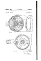
I attain the-foregoing objects by means of the construction and"devices"shown in: the accompanying drawings in which- Figure 1. is a' midsectional side elevation. of 'a" operable ina sleeve 4' which has keys E'adaptedf to engage in splines 6 formed in thespindle. A
driving. element! "is'journalled on the upper part of'sleeve- 4 and has a variablespeedv belt .pulle'y 8, formed on its upper part andasun gear l!) formedon its lower part;
has "radially extending lobes l3"fdrming supports forthebearing. pins. 1510f. idler planetary gears 14 which mesh with. sun gear 16.
A" cup-shapedhousing, E6 is journalled on the lower part ofsie'eve 4 below flange support [2V ally positioned h'ole 32 'in gear housing l6. It isv normally urged upward by asprin 33 set inthe undergroove of head 3| whereby it engagesin the detainingnotches it'between lobes ls'of sleeve flange 12.
A forkisfi is secured in a channel 31in head frame plate 2! so that it may be operated inand out. radially. relative. to the spindle axis. The
inner end ofv this. fork isslotted toiorm tines 38 which .are beveled on their under "facesito engage over the nut or head 39 of pin 30. When moved inwardly these tines engage head 39 on the lower end of locking pin 30 and the beveled faces .force this pin downward into recess 49 inplate 2l' against the tension of sprin st. In thisposition the sleevaplate I2 is released'and. rotates separately from the ring gear housing while the housing it is held in fixedpposition by the nut 39 on the stop pin 33'. Rotary motion is then' transmitted from the driving element 1 through its sun .gear I i and. idler gears I 4 to p1ate'l2 and sleeve 4, which. turns at reduced speed;
When fork Solis moved. radially outward the pin 30 is released and moves upward under: the urge ofspring 33, to engage in any one of the notches between'the lobes E3 of flange 12. When in this position the case IEi-andflange l2 operate togetheras a unit and "the gearing is'locked; The spindle then rotates at the'speed of the driving element 1:
The drivirigelement has a double flanged pulley for'v belt 56 withone stationary flange 5! and the other flange-52" held resiliently toward the stationaryfiange hysprings Variation of the tension ofthe belt'willalterthe effective radial above described, I provide an annularoil groove so formed in the lower face of driving element 7. Casing I6 is sealed at the bottom by sealed ball bearing 62 and around its upper rim by a ring 63 of soft rubber like material set into an annular groove in the upper edge of the casing and having an inwardly extending lip 6| adapted to engage against the outer face of ring 65 on the lower face of driving element 1. Arcuate slots 64 cut through plate l2 near its hub have end walls 65 slanting downwardly and outwardly in each direction. These slots enable oil forced outward and downward from the space 8i), and from the space above idler gears Hi, to escape upward from space 68 between the bottom of the ring gear housing and the lower face of plate 12. The rotation of this plate and its radially extending lobes forces this oil outward to the rim H of the housing I6. The forcing of the oil outwardly creates a zone of low pressure at the inner annuli above slots E i, and a zone of higher pressure at the peripheral area. This differential pressure forces the oil at the peripheral area downwardly and inwardly through space 68, and thence upwardly through arcuate holes 64. All the interior cup-like space of housing 56 is filled with heavy oil through filling hole 89 (Figure 6).
From the foregoing it will be seen that the spindle or shaft 2 is keyed to and driven by the sleeve 4. This sleeve may be driven either directly by the driving element l or indirectly through the planetary gearing composed of the sun gear l9, idler gears I l and ring gear ii, at a reduced speed. In either case the speed of the driving element i may be varied by changing the tension of the belt running over pulley 8.
The sleeve 4 is rigidly supported and journalled in the head frame of the drill press by bearings 26 and 29. The spindle may be independently journalled in such other and suitable bearings as may be necessary to maintain it in alinement.
The change from direct drive, when pin 38 engages in the notches 34 and case i6 is free to rotate can be accomplished easily by stopping the driving motor and rotating the casing to the place where pin 39 is alined with the notch of the slide fork 36. The fork is then forced inward. This causes its tines to engage over the lower pin head 39 and draw the pin downward into the hole in which it operates in the casing until it is flush with the bottom iii of the cupped portion of the casing. At the same time the casing IE is locked relative to the frame. A spring ll on slide 3'! engages a cavity E2 on the upper face of fork 36 to detain it in this inner position as shown in Figure 1.
When it is desired to change back to direct drive it is only necessary to withdrawn the fork to the outer position shown by dotted outline in Figure 3 where it is maintained by engagement of spring H in cavity E3. The pin 30 then slides upward under the urge of spring 33. In doing this it will move into any one of the notches 34. It is unnecessary to stop the drive during this change, since the speed of flange i2 is not excessive. However to cushion the shock when the upper end of pin 38 engages the notch, rubber bumpers 14 are provided on all radial faces of lobes I3. It will be observed that the pin 39 and fork 36 are proportioned and positioned so that the fork releases the pin and the case I6 is free to rotate before the pin engages the lobe notches on plate I2.
The form of drive head here illustrated and described is particularly adapted for use on drill presses, but it is at once obvious that spindle 2 can be replaced by any other shaft desired to be driven to operate other light shop machinery. In all cases a high and low speed is made available by shifting from direct to gear driven speed, and intermediate speeds are obtained by varying belt tension on pulley 8. Thus the drive head is a unit which is both compact and sturdy and is extremely easy to operate.
Whereas I have illustrated and described but one exemplary form of my device I realize that there can be many changes and substitutions of parts, none of which would alter the spirit or intendments of the invention. Therefore, I wish to be limited only by the claims.
I claim:
1. A speed change driving unit for drill presses or the like comprising a driven spindle, a driving sleeve having a flange with radially extending lobes forming detaining notches therebetween splined on said spindle, a driving element having a variable speed V belt pulley at its top and a sun gear at its bottom journalled on said sleeve above said flange, a casing having an annular rim at its top with a ring gear on the inner face thereof, journalled on said sleeve below said flange, planetary idler gears journalled on stub shafts on said flange lobes parallel to said spindle, meshing with said sun gear and said ring gear, support frame bearings journalled at each end of said spindle, one of said bearings being adjacent said casing and having a radially extending slide, a pin engaging fork having tines beveled on their bottom faces at its inner end operative in said slide, means for detaining said casing from rotation, or interlocking said casing and said sleeve, comprising a stop pin radially positioned in the lower portion of said casing operative parallel to said spindle axis and adapted to engage in said spindle flange detaining notches when in raised position, a spring urging said pin to raised position, a head on the lower end of said pin engageable by the tines of said fork whereby it may be retracted to lowered position freeing it from said flange notch and restraining said casing from rotation.
2. In a speed change head for drill presses, having a sleeve with a flange carrying idler planetary gears, a drive element having a sun gear meshing with said idler gears and a peripheral portion adapted to contact a resilient sealing ring, a casing having an upturned rim carrying a ring gear meshing with said idler gears, an oiling system including an annular oil retaining cavity formed on the bottom face of said drive element above said sun gear having a filling hole opening through the upper part of said drive element, a cup-shaped cavity formed in the upper face of said casing to receive said flange and idler gears and, retain oil to immerse said gearing, a sealing bearing between said casing and said sleeve, a resilient sealing ring between the upper edge of said casing and said peripheral portion of said drive element, arcuate openings having a trapezoidal elevation formed in said flange adjacent said spindle connecting said oil retaining cavity in said casing with the area above said flange adjacent said oil retaining cavity in said driving element.
3. In a speed change head for power driven machinery including a supporting frame, having bearings journaling a sleeve, a driving element having a sun gear journaled on said sleeve, a driven spindle shaft keyed to said sleeve, a cylindrical casing journaled on said sleeve having a cup shaped recess on its upper face provided with an internal ring gear, said sleeve having a flange midpositioned relative to its length with radially extending lobes thereon and detaining notches therebetween; and planetary idler gears operative on said lobes between said sun gear and said ring gear; in combination therewith, mechanism for shifting from direct drive to planetary gear drive, including a detaining pin slidably operative in a radially positioned hole in said casing having an undercut upper head adapted to engage in said detaining notches when in raised position, rubber inserts on the contacting faces of said notches, a spring secured in said head undercut normally urging said pin upward relative to said casing and to engaging position With any one of said notches, a lower head on said pin, a radially extending slide secured to said frame, a fork bar operative therein having a fork at its inner end with tines adapted to embrace the lower end of said detaining pin and bevels on 29 ed to detain said slide in either an inner position with said tines engaging said detaining pin fork or an outer position with said tines retracted therefrom; said casing, detaining pin, and fork being arranged so that when said fork is moved to said inner position said tines engage the lowerhead of said detaining pin and force it into the hole in said slide and move said upper head from said notch engaging position.
ELSON THOMAS BARNETT.
REFERENCES CITED The following references are of record in the file of this patent:
UNITED STATES PATENTS Number Name Date 544,776 Souder Aug. 20, 1895 660,547 Dyer Oct. 23, 1900 862,861 Barnes Aug. 6, 1907 2,089,363 Haas Aug. 10, 1937 2,281,353 Hubbard Apr. 28, 1942 2,427,168 Thompson Sept. 9, 1947
Priority Applications (1)
| Application Number | Priority Date | Filing Date | Title |
|---|---|---|---|
| US48985A US2544061A (en) | 1948-09-13 | 1948-09-13 | Speed change driving head for power-driven machines |
Applications Claiming Priority (1)
| Application Number | Priority Date | Filing Date | Title |
|---|---|---|---|
| US48985A US2544061A (en) | 1948-09-13 | 1948-09-13 | Speed change driving head for power-driven machines |
Publications (1)
| Publication Number | Publication Date |
|---|---|
| US2544061A true US2544061A (en) | 1951-03-06 |
Family
ID=21957480
Family Applications (1)
| Application Number | Title | Priority Date | Filing Date |
|---|---|---|---|
| US48985A Expired - Lifetime US2544061A (en) | 1948-09-13 | 1948-09-13 | Speed change driving head for power-driven machines |
Country Status (1)
| Country | Link |
|---|---|
| US (1) | US2544061A (en) |
Cited By (3)
| Publication number | Priority date | Publication date | Assignee | Title |
|---|---|---|---|---|
| US2734400A (en) * | 1956-02-14 | andershock | ||
| US3055236A (en) * | 1960-08-05 | 1962-09-25 | Rockwell Mfg Co | Planetary gear pulley and control means |
| US4519261A (en) * | 1981-11-17 | 1985-05-28 | Mitsubishi Denki Kabushiki Kaisha | Starting motor with planetary gear reduction gears |
Citations (6)
| Publication number | Priority date | Publication date | Assignee | Title |
|---|---|---|---|---|
| US544776A (en) * | 1895-08-20 | Velocipede | ||
| US660547A (en) * | 1899-10-14 | 1900-10-23 | Henry Dyer | Compound bicycle-gear. |
| US862861A (en) * | 1907-05-02 | 1907-08-06 | W F & John Barnes Company | Drilling-machine. |
| US2089363A (en) * | 1936-05-23 | 1937-08-10 | Haas Alvin | Machine tool |
| US2281353A (en) * | 1939-02-20 | 1942-04-28 | Russel R Fray | Full universal all-speed milling attachment |
| US2427168A (en) * | 1943-06-11 | 1947-09-09 | Roy E Thompson | Driving gear unit |
-
1948
- 1948-09-13 US US48985A patent/US2544061A/en not_active Expired - Lifetime
Patent Citations (6)
| Publication number | Priority date | Publication date | Assignee | Title |
|---|---|---|---|---|
| US544776A (en) * | 1895-08-20 | Velocipede | ||
| US660547A (en) * | 1899-10-14 | 1900-10-23 | Henry Dyer | Compound bicycle-gear. |
| US862861A (en) * | 1907-05-02 | 1907-08-06 | W F & John Barnes Company | Drilling-machine. |
| US2089363A (en) * | 1936-05-23 | 1937-08-10 | Haas Alvin | Machine tool |
| US2281353A (en) * | 1939-02-20 | 1942-04-28 | Russel R Fray | Full universal all-speed milling attachment |
| US2427168A (en) * | 1943-06-11 | 1947-09-09 | Roy E Thompson | Driving gear unit |
Cited By (3)
| Publication number | Priority date | Publication date | Assignee | Title |
|---|---|---|---|---|
| US2734400A (en) * | 1956-02-14 | andershock | ||
| US3055236A (en) * | 1960-08-05 | 1962-09-25 | Rockwell Mfg Co | Planetary gear pulley and control means |
| US4519261A (en) * | 1981-11-17 | 1985-05-28 | Mitsubishi Denki Kabushiki Kaisha | Starting motor with planetary gear reduction gears |
Similar Documents
| Publication | Publication Date | Title |
|---|---|---|
| US2544061A (en) | Speed change driving head for power-driven machines | |
| US3677109A (en) | Continuously variable friction gear | |
| US3762231A (en) | Variable diameter pulley | |
| US2891435A (en) | Lathe | |
| US2076926A (en) | Variable speed power drive | |
| US2218712A (en) | Variable speed control for the transmission of power | |
| US2075216A (en) | Valve seat lapping machine | |
| US3608386A (en) | Cam operated variable ratio belt drive | |
| US3055236A (en) | Planetary gear pulley and control means | |
| US2753575A (en) | Drive release for taper threading die head | |
| US2297078A (en) | Drill press | |
| US2399451A (en) | Power pulley | |
| US1808539A (en) | Speed changing transmission mechanism | |
| US2956450A (en) | Fluid drive and tool incorporating same | |
| US3541895A (en) | Devices for imparting radial displacements to eccentrically rotating parts | |
| CN105134920B (en) | The unlimited formula buncher of mechanical gear | |
| US1475982A (en) | Attachment for drilling machines | |
| GB607356A (en) | Improved method of controlling the action of motor vehicle differential gears | |
| US1197684A (en) | Change-speed mechanism. | |
| US2501936A (en) | Variable-speed drive | |
| US2676494A (en) | Change-speed gear device | |
| US1032245A (en) | Variable-speed gearing for motor-cycles. | |
| US2272048A (en) | Headstock | |
| US2919594A (en) | Variable speed and constant power chuck for lathes and other machine tools | |
| US2810303A (en) | Variable drive transmission unit |