US2543915A - Produce treating apparatus - Google Patents
Produce treating apparatus Download PDFInfo
- Publication number
- US2543915A US2543915A US711911A US71191146A US2543915A US 2543915 A US2543915 A US 2543915A US 711911 A US711911 A US 711911A US 71191146 A US71191146 A US 71191146A US 2543915 A US2543915 A US 2543915A
- Authority
- US
- United States
- Prior art keywords
- produce
- treating
- frame
- tank
- sudsing
- Prior art date
- Legal status (The legal status is an assumption and is not a legal conclusion. Google has not performed a legal analysis and makes no representation as to the accuracy of the status listed.)
- Expired - Lifetime
Links
- 239000007788 liquid Substances 0.000 description 18
- 239000006260 foam Substances 0.000 description 10
- 230000004048 modification Effects 0.000 description 10
- 238000012986 modification Methods 0.000 description 10
- 230000007246 mechanism Effects 0.000 description 9
- 239000000872 buffer Substances 0.000 description 5
- 239000004744 fabric Substances 0.000 description 5
- 238000005187 foaming Methods 0.000 description 5
- 230000009471 action Effects 0.000 description 3
- 238000004891 communication Methods 0.000 description 3
- 230000000694 effects Effects 0.000 description 3
- 239000000839 emulsion Substances 0.000 description 3
- 230000006872 improvement Effects 0.000 description 3
- 239000000463 material Substances 0.000 description 3
- 230000008901 benefit Effects 0.000 description 2
- 230000001276 controlling effect Effects 0.000 description 2
- 235000012055 fruits and vegetables Nutrition 0.000 description 2
- 239000000203 mixture Substances 0.000 description 2
- 230000001105 regulatory effect Effects 0.000 description 2
- VTYYLEPIZMXCLO-UHFFFAOYSA-L Calcium carbonate Chemical class [Ca+2].[O-]C([O-])=O VTYYLEPIZMXCLO-UHFFFAOYSA-L 0.000 description 1
- 229940069428 antacid Drugs 0.000 description 1
- 239000003159 antacid agent Substances 0.000 description 1
- 230000001458 anti-acid effect Effects 0.000 description 1
- 230000000712 assembly Effects 0.000 description 1
- 238000000429 assembly Methods 0.000 description 1
- 239000011248 coating agent Substances 0.000 description 1
- 238000000576 coating method Methods 0.000 description 1
- 238000010276 construction Methods 0.000 description 1
- 238000000034 method Methods 0.000 description 1
- 238000005498 polishing Methods 0.000 description 1
- 230000008569 process Effects 0.000 description 1
- 230000000717 retained effect Effects 0.000 description 1
Images


Classifications
-
- A—HUMAN NECESSITIES
- A23—FOODS OR FOODSTUFFS; TREATMENT THEREOF, NOT COVERED BY OTHER CLASSES
- A23B—PRESERVATION OF FOODS, FOODSTUFFS OR NON-ALCOHOLIC BEVERAGES; CHEMICAL RIPENING OF FRUIT OR VEGETABLES
- A23B7/00—Preservation of fruit or vegetables; Chemical ripening of fruit or vegetables
- A23B7/16—Coating with a protective layer; Compositions or apparatus therefor
-
- B—PERFORMING OPERATIONS; TRANSPORTING
- B05—SPRAYING OR ATOMISING IN GENERAL; APPLYING FLUENT MATERIALS TO SURFACES, IN GENERAL
- B05C—APPARATUS FOR APPLYING FLUENT MATERIALS TO SURFACES, IN GENERAL
- B05C5/00—Apparatus in which liquid or other fluent material is projected, poured or allowed to flow on to the surface of the work
-
- Y—GENERAL TAGGING OF NEW TECHNOLOGICAL DEVELOPMENTS; GENERAL TAGGING OF CROSS-SECTIONAL TECHNOLOGIES SPANNING OVER SEVERAL SECTIONS OF THE IPC; TECHNICAL SUBJECTS COVERED BY FORMER USPC CROSS-REFERENCE ART COLLECTIONS [XRACs] AND DIGESTS
- Y10—TECHNICAL SUBJECTS COVERED BY FORMER USPC
- Y10S—TECHNICAL SUBJECTS COVERED BY FORMER USPC CROSS-REFERENCE ART COLLECTIONS [XRACs] AND DIGESTS
- Y10S118/00—Coating apparatus
- Y10S118/06—Fruit coater
Definitions
- PRODUCE TREATING APPARATUS Filed Nov. 23, 1946 5 Sheets-Sheet 5 Patented Mar. 6, 1951 UNITED STATES PATENT OFFICE PRODUCE TREATING APPARATUS David Elwyn Leonard, Orlando, Fla., assignor to American Machinery Corporation, Orlando, Fla., a corporation of Florida Application November 23, 1946, Serial No. 711,911
- This invention relates to. produce-treating equipment and, more particularly, to improvements in'apparatus, as shown and described in U. S. Letters Patent No. 2,430,187 for applying a thin, uniform and polished film, such as wax, to the surfaces of produce.
- the object of the present invention is to provide an apparatus, as mentioned, that admits of a more uniform control of the coating material delivered to the produce being treated and that is economical in construction and use for the commercial purposes.
- the sudser comprises a suitable source of solution, such as a supply tank, which is arranged to feed into a control tank that is adapted to maintain a predetermined solution level in a mixing or sudsing tank. with which it is in communication.
- the sudsing tank is relatively narrow but is sufficiently long to extend the full width of a standard produce-treating bed.
- a perforated airline extends along the bottom of the mixing or sudsing tank and this airline is surrounded by a fabric sock which acts to separate the air, that is forced through the airline, into small bubbles and to diffuse or disperse these bubbles through the solution Within the mixing tank. This action aerates the solution which causes it to foam or suds-up and overflow the tank to a delivery chute for directing the suds down onto the produce below.
- the sudsing aparrangement permits the adjustment of the buffers relative to the treating bed in order to regulate the wiping and buffing effect and to accommodate produce of different sizes.
- the sudsing apparatus is adjustably mounted on the supporting frame of the buffing mechanism in order that it (1) may be adjusted to a position that is substantially level along the length of the suds feed chute, (2) may be tilted so as to vary the inclination of the feed chute, and, (3) may be variably spaced, relative to the frame, so as to position the feed chute to drop the suds directly upon the produce or onto the buffers which in turn apply them to the produce.
- the sudsing apparatus may be assembled as a unit with the compressor and the motor, and this unit may be adapted for mounting upon the treating machine.
- the motor may be replaced by a drive shaft which may be driven by the power equipment for the treating machine, as by means of a belt, a chain or the like, thus eliminating the duplication of power equipment, but without departing reference characters indicate like parts throughparatus may be formed as a unit which may be applied directly to a brush bed machine or be mounted upon a frame that supports a buffin mechanism overlying the machine bed, and which supporting frame is vertically adjustable relative to the machine bed and upon which may be mounted an air compressor to supply air to the mixing tank and a motor for driving the compressor.
- the bufiing mechanism is preferably in the form of a plurality of rag rollers which comprise a plurality of canvas strips extending radially from a supporting shaft.
- these rollers are removably journaled on a separate frame as above mentioned which telescopes around a side-enclosing-housing or hood which is slotted to accommodate the buifer shafts and which may be attached directly to any produce-tr ati g machine out and in which:
- Fig. 1 is a View in perspective of a producetreating machine having a unitary sudsing and buffing apparatus mounted thereon in accordance with the present invention
- Fig. 2 is a side view in elevation of the machine shown in Fig. 1 with the preferred form of sudsing and buffing unit mounted thereon;
- Fig. 3 is a side view in elevation of the preferred form of sudsing and buffing unit
- Fig. 4 is a top plan view of the unit shown in Fig. 3;
- Fig. 5 is a cross sectional view taken on line 5-5 of Fig. 3;
- Fig. 6 is an end view in elevation of the preferred form of bufiing element
- Fig. 7 is a side view in elevation of the pre- .ferred form of buffing element
- Fig. 8 is a front view in elevation of a modified form of sudsing unit.
- Fig. 9 is a cross sectional view taken on line 9-9 of Fig. 8.
- An apparatus of the present type should have the distinctcharacteristics of comprising an independent unitary structure that may be readily assembled or disassembled with any desired treating machine and which is capable of supplying a predetermined amount of film-forming material in an economical manner by means of a sud or foam, and is adapted for varying the wiping and bufiing effect upon the produce in accordance with the texture and thickness of film desired. Accordingly, an embodiment of the invention, referring to Figs.
- a sudsing equipment In that is combined' as a unit with a buffing mechanism H and machine, an inclined slat dump [4 upon which the produce may be dumped and between the slats of which dirt, rubbish, and immature produce may drop and be eliminated, an endless conveyor l5, which in the present instance is in the form of a roller-belt conveyor, a spray-type washer 16 through which the produce is carried by the conveyor so that loose dirt may be washed therefrom, a grading space I69 over which the produce is carried by the conveyor while operators pick undesirable produce therefrom and at the upper end of which is positioned the sudsing and buffing unit lfi-l l, and a supply chute I! for feeding the processed produce from the conveyor l5 to any desired v ype 0f collector such as a picking table or hamper.
- any desired v ype 0f collector such as a picking table or hamper.
- the sudsing and bufimg equipment comprises a control tank 29 having an inlet 2
- the control valve 22 may be of any desired type that will render accurate control and preferably is in'the form of a simple float valve, although a needle valve or other adjustable posi- 'tive means may be employed.
- the control tank 20 is mounted in fixed relation with the mixing tank 23 and is placed in communication therewith by a suitable connection 24, such as an elbow pipe.
- the mixing tank 23 is a relatively narrow tank that is arranged to extend the full width of the apparatus and is somewhat taller than the control tank.
- An airline 25 is positioned in the" bottom of the mixing tank 23 and extends substantially the full length thereof, as best shown in Fig. 8.
- the airline 25 may be in the form of a perforated tube and is surrounded by a canvas sock 26, and is connected with an air supply line 21. Accordingly, when air is supplied under pressure, through the line 21 to the perforated pipe 25, the air is expelled in small streams into the sock 25 and through the sock into the solution in the tank 23.
- the sock 26 causes the air to break up into fine bubbles that are dispersed or diffused through the liquid and has the effect of carbonating or aerating the liquid which causes it to foam up within the tank 23 to form suds.
- the wall 28 of the mixing tank 23 terminates somewhat short of the top of the tank and is formed over with a downwardly inclined chute 29 having serrated, notched or fluted edge 30 to evenly distribute the suds across the full Width of the treating area.
- the solution or emulsion may be supplied to the control tank 20 from any suitable source but in the preferred form a supply tank 3
- the control tank 20 and the mixing tank 23 may be formed as an integral unit or may have their adjoining walls secured together.
- a pair of vertical brackets 33 may be attached, one to opposite ends of the mixing tank 23, and have arms 34, extending angularly from their upper ends, upon which the supply tank 3
- the brackets 33 also act as supports for the sudsing equipment combined structure and, to this end, are provided with pairs of vertical slots 35, as best shown in Fig.
- brackets 33 for receiving suitable mountings, such as stud bolts 4
- the buffer mechanism may comprise a plurality of wiping, buffing or polishing elements 43 removably mounted on the lower side members of the frame 49 so that different types of elements may be inserted as desired to permit versatility of use.
- These elements 43 comprise shafts 44 having bearings 45 journalled in expansible bearings 43 supported by clamps 4T removably secured to the frame 40 by bolts 48. Three of these assemblies are shown in the drawings, but it will be understood that any desired number of the elements 43 may be employed.
- the elements 43 comprise wiping or bufling members formed by a plurality of radially disposed canvas strips, as best shown in Figs. 6 and 7. These elements comprise canvas strips 43 perforated centrally thereof so as to fit over their shaft 44.
- the strips 49 are preferably mounted in groups of four that are positioned about the shaft 44 at 45 relative to each other and the groups are clamped together and spaced from each other by collars 5D.
- a fixed collar BI is positioned on one end and a nut 52 is threaded on the other end of the shaft 44 to clamp the groups of strips and the collars tightly together.
- This structure forms a rag roller that is soft and fiexible and produces an excellent wiping and bufiing action but does notbecome clogged, caked or matted with wax.
- the structure is such that the elements may be refurbished by the operator simply by removing the nut 52 and replacing the cloth strips 49 which the operator may cut from any piece of cloth.
- the frame 40 is telescopically supported by a housing or shielding member 53 adapted to be mounted upon any desired type of produce-treating machine above the treating bed I5 thereof.
- the housing 53 may be secured to the machine in any desired manner, as by bolts 54 or other suitable means.
- the housing 53 is designed to prevent splattering or throwing of the suds, but its bottom is open as may be its top.
- the frame 40 fits around the outside of the housing 53 and is suspended from the top of the housing by means of hanger bolts 55 supported from the brackets 56 secured to the top edges of the housing and extending through the antacid lower side members of the frame it.
- the frame 41! by adjusting the nuts 51 on the bolts '55; the frame 41!, with the elements 43, w'ill beraised or lowered relative to the housing 53' and the treating bed iii in order to regulate the thickness and type of film formed on the produce according to the extent of the wiping or buffing. pressures and also in order to accommodate produce of different graded sizes.
- the frame to" is preferably outside of the hood 53, the sidewalls 58 of the housing 53 are provided with vertical slots 5; to accommodate the shafts M of the elements 43'. It will be understood that, if. desired, the sudsing equipment ill maybe removed or its operation discontinued and the adjustably' mounted buffing mechanism H may be employed as a sepa rate unit.
- This power equipment comprises an air pump or compressor 66 that is connected with the air supply line 2"! for feeding" air into the mixing tank 23.
- the power equipment also comprises a drive shaft cl including" a fly Wired 82 and a drive sprocket t3 for driving the sprockets (i i of the elements 53- by means of a chain
- the chain 65 meshes with. the bottoms of the sprockets t4 and is retained engagement by a slideway 55.
- the power equipment comprises a unitary source of power and is mounted on the frame M for driving both the compressor as and the drive shaft 61.
- this source of power may be in the form of a suitable engine or motor 6 upon the shaft 88 of which may be mounted Suitable drive means, such as pulleys 69, which may be connected to drive the compressor 58' shaft 6 l' by means of belts Hi and M, respectively.
- the unitary source of power may be in the form of a power shaft 58 which may be driven by means of a sprocket l5 and chain It by the power unit ll of the treating machine i2.
- a single source of power is employed for operating the treating machine and the sudsing and buffing equipment.
- the sudsing equipment is adapted as a unitary structure for use with machines comprising beds formed of rotated brushes and with which the buffers are not necessary.
- This structure is best shown in Figs. 8 and 9 and is very similar to the hereinbeiore described sudsing equipment, al though slight modifications are shown to illustrate variations contemplated as being within the scope of invention.
- the control tank 26 and the mixing tank 23' are formed in substantially the same manner except that a communicating opening 24 is formed directly between the two tanks in lieu of the outside elbow connection 25 shown in the previously described modification.
- the control tank 26 may be provided with an inlet 2! and a control valve 22 and the mixing tank 23 may be provided with a perforated airline 25 which is surrounded by a canvas sock 23.
- control tank 2t may be open at the top due to the fact that it is protected by the superimposed supply tank 3
- the control tank 2b is provided with a hinged cover 96 because, for purposes of illustration, a separate source of supply is substituted for the self-contained tank 3
- Supporting brackets 33 are mounted on the ends of the mixing tank 23' and these brackets diifer only in that they do not have the arms 34 may be substituted therefor.
- the brackets 33 are socured to an inverted U-shape'd frame 9
- These bolts 92 are shown asbeing ordinary bolts that clamp the bracketsdirectly to the surface of the frame 91, but it will be understood that the fixed bolts M
- a compressor and motor El may be mounted on the top of the frame 91 and drivingly connected by belt. 10.
- the motor 6'! may be smaller than the motor 61 in View of the fact that its load comprises the compressor til only, and not the buffing mechanism.
- the compressor St may be connected with the supply pipe 2 for feeding air to the mixing tank 23.
- the frame 91 is adaptedv for positioning on atreating machine by means of angle members 93 which are fixed in a horizontal position by attaching their vertical flanges 94 to the outsides of the lower ends of the frame 9! so that their, horizontal flanges 95 extend laterally to form supportin brackets for cooperating with the superstructure of the produce-treating machine.
- the treating bed I5" is formed by a plurality of rotatably mounted brushes 9% which spread and polish the emulsion supplied to the produce and thereby form an unbroken film.
- the treating bed 15 is confined by the sidewalls 91 of the' machine and angle brackets 99 are fixed to the inner sides of the sidewalls to form supports for the frame-supporting flanges 95 of the brackets 93.
- This modification forms a compact, selfcontained suds-producing unit that may be employed with machines of the brush type and with which the buffing elements are unnecessary.
- a suitable supply of wax emulsion or other desirable type of liquid or solution may be provided in the supply tank 3
- the liquid is supplied through the inlet 2! to the control tank 20, or 2B, in quantities regulated by the adjustable control valve 22.
- the control tank 20, or 26' being in communication with the mixing tank 23 or 23', by means of the connection 24, or 24, the control of the liquid level in the control tank acts to maintain the liquid at the same level in the mixing tank 23, or 23.
- Air under pressure is supplied in the bottom of the mixing tank and throughout the length thereof by a perforated airline 25 and through a fabric tube or sock 26 which surrounds the airline and divides the air into small bubbles before it is diffused or dispersed through the liquid in the mixing tank.
- the introduction of the air into the liquid transforms the liquid into a foaming or sudsy mixture to thereby materially increase it in volume with a consequent decrease in density.
- the foaming of the mixture causes it to rise in the mixing chamber and to flow over the lower edge, of a wall 28, of the chamber to spill down the feed chute 29 which distributes it over the produce under treatment.
- the mixing chamber is relatively narrow so that the one airline will be sufiicient to aerate all of its contents and so that the mass will be so confined that it will readily foam up to overflow.
- the sudsing equipment is assembled as a unit which may be adjustably supported by brackets 33, or 33', in order that it may be properly leveled even though the treating machine upon which it is mounted is not level.
- the supporting brackets 33, or 33' provide the additional advantage of permitting the sudsing equipment to be tilted to raise or lower the feed chute 29 to regulate the fiow of the suds and also permitting the spacing of the equipment, both horizontally and vertically, relative to its supporting structure.
- the sudsing equipment may be employed separately in conjunction with brush type treating machines, such as shown in Fig. 8, or it may be combined with a buffin mechanism, as shown in Figs. 1 and 2, which may evenly and lightly buff the suds on the produce into a thin, unbroken film.
- the frame 40 is not mounted directly upon the treating machine, but is supported by and around a housing 53 that is mounted on the machine.
- the frame 40 is suspended on hanger bolts 55 which are hun from the top of the housing 53.
- This telescopic arrangement permits adjustment of the frame 40 to raise or lower the buffing elements 43 in order to accommodate produce of different sizes or to regulate the pressure applied upon the produce.
- a device for supplying a foamed treating liquid to edible produce as it is conveyed on an underlying treating bed comprising a foam producing apparatus including a mixing or foaming chamber, a feed chute extending from the upper portion of the chamber and adapted to extend substantially across the treating bed to deliver foam from the chamber onto the produce being treated, a perforated airline in the lower portion of the chamber for aerating the liquid therein and to transform said liquid into a foam, the improvement consisting of an inflatable fabric tube surrounding the airline to finely divide the air before it is dispersed into said liquid and a supporting frame means adapted to support said apparatus above the treating bed and including adjustable means for maintaining said apparatus on said framein adjustable positions, said adjustable means being operable to level horizontally or tilt vertically said chute relative to the treating bed to regulate the amount and evenness of the flow of foam to the treating bed.
- a device for attachment to machines having a treating bed for edible produce and for applyin a film to said produce comprising. a splash shield adapted to be mounted upon said machine above said treating bed, a frame disposed above said treating bed, rotatable bufling elements journalled in said frame to engage the produce being treated on the bed, means supporting the frame from said splash shield and adjustable vertically to space said buifing elements relatively to said treating bed to regulate the action of said bufiing elements on said produce, a liquid foaming apparatus carried by said frame, a feed chute extending from said apparatus and positioned to deliver foam therefrom onto the produce on the treating bed and in advance of said buffing elements, and adjustable means between said frame and said apparatus for varying the angular positions of said chute whereby the amount and evenness of distribution of said foam delivered to the treating bed may be regulated.
- a device for treating produce such as fruits and vegetables, and which comprises a splashshield adapted for mounting upon the top portion of a produce-treating machine having an underlying treating bed therein, hanger bolts suspended from said shield, a frame telescopically disposed with respect to said shield and adjustably supported by said hanger bolts, rotatable buffing elements removably journalled on said frame, a liquid foaming apparatus, brackets attached to said apparatus, adjustable means on said frame for removably supporting said brackets in angularly adjusted positions, and a feed means extending from one side of said apparatus and disposed to deliver suds therefrom onto the produce on the treating bed in advance of said bufiing elements.
- a device for treating produce such as fruits and vegetables, and which comprises a splashshield adapted for mounting upon the top portion of a produce-treating machine having an underlying treating bed, a frame telescopically disposed with respect to said shield, means adjustably supporting said frame from said shield for adjustment to and from said treating bed, rotatable bufiing elements journalled in said frame to contact with the produce being treated on and supported by said treating bed, a dispensing apparatus for material with which the prodnets are treated, means on said frame for supporting said apparatus in adjusted positions relative to said treating bed, and a distributing means receiving dispensed liquid from said apparatus to deliver said liquid on to the produce on the treating bed.
- a splashshield adapted for mounting upon the top portion of a produce-treating machine having an underlying treating bed, a frame telescopically disposed with respect to said shield, means adjustably supporting said frame from said shield for adjustment to and from said treating bed, rotatable bufiing elements journalled in said frame to contact with the produce being
Landscapes
- Chemical & Material Sciences (AREA)
- Life Sciences & Earth Sciences (AREA)
- Engineering & Computer Science (AREA)
- Chemical Kinetics & Catalysis (AREA)
- General Chemical & Material Sciences (AREA)
- Wood Science & Technology (AREA)
- Zoology (AREA)
- Food Science & Technology (AREA)
- Polymers & Plastics (AREA)
- Treatment Of Fiber Materials (AREA)
Description
D. E. LEONARD PRODUCE TREATING APPARATUS March 6, 1951 5 Sheets-Sheet 1 Filed Nov. 25, 1946 INVENTOR. DAVID E. LEONARD March 6, 1951 D. E. LEONARD PRODUCE TREATING APPARATUS 5 Sheets-Sheet 2 Filed Nov. 23, 1946 INVENTOR. DAVID E- LEONARD FIG. 4
March 6, 1951 D. E. LEONARD PRODUCE TREATING APPARATUS 5 Sheets-Sheet 3 Filed Nov. 23, 1946 ATTORNEY March 6, 1951 D. E. LEONARD 2,543,915
PRODUCE TREATING APPARATUS Filed Nov. 23, 1946 5 Sheets-Sheet 4 MarchG, 1951 LEONARD 2,543,915
PRODUCE TREATING APPARATUS Filed Nov. 23, 1946 5 Sheets-Sheet 5 Patented Mar. 6, 1951 UNITED STATES PATENT OFFICE PRODUCE TREATING APPARATUS David Elwyn Leonard, Orlando, Fla., assignor to American Machinery Corporation, Orlando, Fla., a corporation of Florida Application November 23, 1946, Serial No. 711,911
4 Claims. 1.
This invention relates to. produce-treating equipment and, more particularly, to improvements in'apparatus, as shown and described in U. S. Letters Patent No. 2,430,187 for applying a thin, uniform and polished film, such as wax, to the surfaces of produce.
The object of the present invention is to provide an apparatus, as mentioned, that admits of a more uniform control of the coating material delivered to the produce being treated and that is economical in construction and use for the commercial purposes.
The foregoing and other objects ancillary thereto are preferably accomplished, in accordance witha preferred embodiment of the invention, by a unitary structure including a sudsing apparatus and buffing mechanism. adaptedfor attachment to any produce-treating machine. Specifically, the sudser comprises a suitable source of solution, such as a supply tank, which is arranged to feed intoa control tank that is adapted to maintain a predetermined solution level in a mixing or sudsing tank. with which it is in communication. The sudsing tank is relatively narrow but is sufficiently long to extend the full width of a standard produce-treating bed. A perforated airline extends along the bottom of the mixing or sudsing tank and this airline is surrounded by a fabric sock which acts to separate the air, that is forced through the airline, into small bubbles and to diffuse or disperse these bubbles through the solution Within the mixing tank. This action aerates the solution which causes it to foam or suds-up and overflow the tank to a delivery chute for directing the suds down onto the produce below. The sudsing aparrangement permits the adjustment of the buffers relative to the treating bed in order to regulate the wiping and buffing effect and to accommodate produce of different sizes. The sudsing apparatus is adjustably mounted on the supporting frame of the buffing mechanism in order that it (1) may be adjusted to a position that is substantially level along the length of the suds feed chute, (2) may be tilted so as to vary the inclination of the feed chute, and, (3) may be variably spaced, relative to the frame, so as to position the feed chute to drop the suds directly upon the produce or onto the buffers which in turn apply them to the produce.
In a modification wherein the produce is conveyed upon a treating bed formed by roller brushes, the sudsing apparatus may be assembled as a unit with the compressor and the motor, and this unit may be adapted for mounting upon the treating machine. In still another modification,
the motor may be replaced by a drive shaft which may be driven by the power equipment for the treating machine, as by means of a belt, a chain or the like, thus eliminating the duplication of power equipment, but without departing reference characters indicate like parts throughparatus may be formed as a unit which may be applied directly to a brush bed machine or be mounted upon a frame that supports a buffin mechanism overlying the machine bed, and which supporting frame is vertically adjustable relative to the machine bed and upon which may be mounted an air compressor to supply air to the mixing tank and a motor for driving the compressor.
The bufiing mechanism, as disclosed in said patent, is preferably in the form of a plurality of rag rollers which comprise a plurality of canvas strips extending radially from a supporting shaft. In the present improvement, these rollers are removably journaled on a separate frame as above mentioned which telescopes around a side-enclosing-housing or hood which is slotted to accommodate the buifer shafts and which may be attached directly to any produce-tr ati g machine out and in which:
Fig. 1 is a View in perspective of a producetreating machine having a unitary sudsing and buffing apparatus mounted thereon in accordance with the present invention;
Fig. 2 is a side view in elevation of the machine shown in Fig. 1 with the preferred form of sudsing and buffing unit mounted thereon;
Fig. 3 is a side view in elevation of the preferred form of sudsing and buffing unit;
Fig. 4 is a top plan view of the unit shown in Fig. 3;
Fig. 5 is a cross sectional view taken on line 5-5 of Fig. 3;
Fig. 6 is an end view in elevation of the preferred form of bufiing element;
Fig. 7 is a side view in elevation of the pre- .ferred form of buffing element;
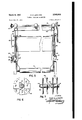
Fig. 8 is a front view in elevation of a modified form of sudsing unit; and
Fig. 9 is a cross sectional view taken on line 9-9 of Fig. 8.
An apparatus of the present type should have the distinctcharacteristics of comprising an independent unitary structure that may be readily assembled or disassembled with any desired treating machine and which is capable of supplying a predetermined amount of film-forming material in an economical manner by means of a sud or foam, and is adapted for varying the wiping and bufiing effect upon the produce in accordance with the texture and thickness of film desired. Accordingly, an embodiment of the invention, referring to Figs. 1 and 2 of the drawings, is constituted by a sudsing equipment In that is combined' as a unit with a buffing mechanism H and machine, an inclined slat dump [4 upon which the produce may be dumped and between the slats of which dirt, rubbish, and immature produce may drop and be eliminated, an endless conveyor l5, which in the present instance is in the form of a roller-belt conveyor, a spray-type washer 16 through which the produce is carried by the conveyor so that loose dirt may be washed therefrom, a grading space I69 over which the produce is carried by the conveyor while operators pick undesirable produce therefrom and at the upper end of which is positioned the sudsing and buffing unit lfi-l l, and a supply chute I! for feeding the processed produce from the conveyor l5 to any desired v ype 0f collector such as a picking table or hamper.
The sudsing and bufimg equipment, best shown in Figs. 3 and 4, comprises a control tank 29 having an inlet 2| and a control valve 22 for admitting a .predeterminedsupply of liquid to the tank 29. The control valve 22 may be of any desired type that will render accurate control and preferably is in'the form of a simple float valve, although a needle valve or other adjustable posi- 'tive means may be employed. The control tank 20 is mounted in fixed relation with the mixing tank 23 and is placed in communication therewith by a suitable connection 24, such as an elbow pipe. The mixing tank 23 is a relatively narrow tank that is arranged to extend the full width of the apparatus and is somewhat taller than the control tank. An airline 25 is positioned in the" bottom of the mixing tank 23 and extends substantially the full length thereof, as best shown in Fig. 8. The airline 25 may be in the form of a perforated tube and is surrounded by a canvas sock 26, and is connected with an air supply line 21. Accordingly, when air is supplied under pressure, through the line 21 to the perforated pipe 25, the air is expelled in small streams into the sock 25 and through the sock into the solution in the tank 23. The sock 26 causes the air to break up into fine bubbles that are dispersed or diffused through the liquid and has the effect of carbonating or aerating the liquid which causes it to foam up within the tank 23 to form suds.
The wall 28 of the mixing tank 23 terminates somewhat short of the top of the tank and is formed over with a downwardly inclined chute 29 having serrated, notched or fluted edge 30 to evenly distribute the suds across the full Width of the treating area.
The solution or emulsion may be supplied to the control tank 20 from any suitable source but in the preferred form a supply tank 3| is mounted immediately above the control tank 20 and is connected with the inlet 2| by a supply line 32. In order to assemble the whole structure as a unit, the control tank 20 and the mixing tank 23 may be formed as an integral unit or may have their adjoining walls secured together. A pair of vertical brackets 33 may be attached, one to opposite ends of the mixing tank 23, and have arms 34, extending angularly from their upper ends, upon which the supply tank 3| may be mounted. In addition to supporting the tank 3|, the brackets 33 also act as supports for the sudsing equipment combined structure and, to this end, are provided with pairs of vertical slots 35, as best shown in Fig. 8, for receiving suitable mountings, such as stud bolts 4| or the like, projecting from each side of a buffer-supporting frame and secured thereto by pairs of lock nuts 42, which may be adjusted to position the brackets 33 at the desired height and at the desired angle for controlling the even distribution and amount of flow of the suds from the mixing tank 23 to the chute 29 and at the desired spacing relative to the frame for controlling the dropping of the suds relative to the buffers.
The buffer mechanism may comprise a plurality of wiping, buffing or polishing elements 43 removably mounted on the lower side members of the frame 49 so that different types of elements may be inserted as desired to permit versatility of use. These elements 43 comprise shafts 44 having bearings 45 journalled in expansible bearings 43 supported by clamps 4T removably secured to the frame 40 by bolts 48. Three of these assemblies are shown in the drawings, but it will be understood that any desired number of the elements 43 may be employed. In the preferred form, the elements 43 comprise wiping or bufling members formed by a plurality of radially disposed canvas strips, as best shown in Figs. 6 and 7. These elements comprise canvas strips 43 perforated centrally thereof so as to fit over their shaft 44. The strips 49 are preferably mounted in groups of four that are positioned about the shaft 44 at 45 relative to each other and the groups are clamped together and spaced from each other by collars 5D. A fixed collar BI is positioned on one end and a nut 52 is threaded on the other end of the shaft 44 to clamp the groups of strips and the collars tightly together. This structure forms a rag roller that is soft and fiexible and produces an excellent wiping and bufiing action but does notbecome clogged, caked or matted with wax. Furthermore, the structure is such that the elements may be refurbished by the operator simply by removing the nut 52 and replacing the cloth strips 49 which the operator may cut from any piece of cloth.
The frame 40 is telescopically supported by a housing or shielding member 53 adapted to be mounted upon any desired type of produce-treating machine above the treating bed I5 thereof. The housing 53 may be secured to the machine in any desired manner, as by bolts 54 or other suitable means. The housing 53 is designed to prevent splattering or throwing of the suds, but its bottom is open as may be its top. In the preferred form, the frame 40 fits around the outside of the housing 53 and is suspended from the top of the housing by means of hanger bolts 55 supported from the brackets 56 secured to the top edges of the housing and extending through the antacid lower side members of the frame it. Thus, by adjusting the nuts 51 on the bolts '55; the frame 41!, with the elements 43, w'ill beraised or lowered relative to the housing 53' and the treating bed iii in order to regulate the thickness and type of film formed on the produce according to the extent of the wiping or buffing. pressures and also in order to accommodate produce of different graded sizes. As the frame to" is preferably outside of the hood 53, the sidewalls 58 of the housing 53 are provided with vertical slots 5; to accommodate the shafts M of the elements 43'. It will be understood that, if. desired, the sudsing equipment ill maybe removed or its operation discontinued and the adjustably' mounted buffing mechanism H may be employed as a sepa rate unit.
In order to complete the unitary structure of this equipment, the necessary power equipment is supported on top of the frame so. This power equipment comprises an air pump or compressor 66 that is connected with the air supply line 2"! for feeding" air into the mixing tank 23. The power equipment also comprises a drive shaft cl including" a fly Wired 82 and a drive sprocket t3 for driving the sprockets (i i of the elements 53- by means of a chain The chain 65 meshes with. the bottoms of the sprockets t4 and is retained engagement by a slideway 55. in addition, the
power equipment comprises a unitary source of power and is mounted on the frame M for driving both the compressor as and the drive shaft 61. As shown Figs. 2 through 4-, this source of power may be in the form of a suitable engine or motor 6 upon the shaft 88 of which may be mounted Suitable drive means, such as pulleys 69, which may be connected to drive the compressor 58' shaft 6 l' by means of belts Hi and M, respectively. In a modified form of the invention, shown in Fig. 1, the unitary source of power may be in the form of a power shaft 58 which may be driven by means of a sprocket l5 and chain It by the power unit ll of the treating machine i2. In this modification, a single source of power is employed for operating the treating machine and the sudsing and buffing equipment.
In still another modification of the invention, the sudsing equipment is adapted as a unitary structure for use with machines comprising beds formed of rotated brushes and with which the buffers are not necessary. This structure is best shown in Figs. 8 and 9 and is very similar to the hereinbeiore described sudsing equipment, al though slight modifications are shown to illustrate variations contemplated as being within the scope of invention. The control tank 26 and the mixing tank 23' are formed in substantially the same manner except that a communicating opening 24 is formed directly between the two tanks in lieu of the outside elbow connection 25 shown in the previously described modification. The control tank 26 may be provided with an inlet 2! and a control valve 22 and the mixing tank 23 may be provided with a perforated airline 25 which is surrounded by a canvas sock 23. Where-- as the previously described control tank 2t may be open at the top due to the fact that it is protected by the superimposed supply tank 3|, the control tank 2b is provided with a hinged cover 96 because, for purposes of illustration, a separate source of supply is substituted for the self-contained tank 3|.
Supporting brackets 33 are mounted on the ends of the mixing tank 23' and these brackets diifer only in that they do not have the arms 34 may be substituted therefor.
for supporting a supply tank 3t in view or the fact that a separate source or supply is employed in the present instance. The brackets 33 are socured to an inverted U-shape'd frame 9| by bolts 92 carried by the frame 9*! and extending. through the slots 35- in the brackets 33. These bolts 92 are shown asbeing ordinary bolts that clamp the bracketsdirectly to the surface of the frame 91, but it will be understood that the fixed bolts M A compressor and motor El may be mounted on the top of the frame 91 and drivingly connected by belt. 10. The motor 6'! may be smaller than the motor 61 in View of the fact that its load comprises the compressor til only, and not the buffing mechanism. The compressor St may be connected with the supply pipe 2 for feeding air to the mixing tank 23.
The frame 91 is adaptedv for positioning on atreating machine by means of angle members 93 which are fixed in a horizontal position by attaching their vertical flanges 94 to the outsides of the lower ends of the frame 9! so that their, horizontal flanges 95 extend laterally to form supportin brackets for cooperating with the superstructure of the produce-treating machine. In the structure shown in Fig. 8 the treating bed I5" is formed by a plurality of rotatably mounted brushes 9% which spread and polish the emulsion supplied to the produce and thereby form an unbroken film. The treating bed 15 is confined by the sidewalls 91 of the' machine and angle brackets 99 are fixed to the inner sides of the sidewalls to form supports for the frame-supporting flanges 95 of the brackets 93. This modification forms a compact, selfcontained suds-producing unit that may be employed with machines of the brush type and with which the buffing elements are unnecessary.
In view of the foregoing description, the operation of the invention should be readily evident.
A review of the process, however, will be in order to properly emphasize its distinguishing characteristics and advantages. To start with, the sudsing equipment, a suitable supply of wax emulsion or other desirable type of liquid or solution may be provided in the supply tank 3|, in the modification shown in Fig. 3, or from a suitable separate source, in the modification shown in Figs. 8 and 9. In either instance, the liquid is supplied through the inlet 2! to the control tank 20, or 2B, in quantities regulated by the adjustable control valve 22. The control tank 20, or 26', being in communication with the mixing tank 23 or 23', by means of the connection 24, or 24, the control of the liquid level in the control tank acts to maintain the liquid at the same level in the mixing tank 23, or 23.
Air under pressure is supplied in the bottom of the mixing tank and throughout the length thereof by a perforated airline 25 and through a fabric tube or sock 26 which surrounds the airline and divides the air into small bubbles before it is diffused or dispersed through the liquid in the mixing tank. The introduction of the air into the liquid transforms the liquid into a foaming or sudsy mixture to thereby materially increase it in volume with a consequent decrease in density. This produces a thin, light, medium for application to the produce, that is capable of forming a thin, unbroken film of uniform thickness. The foaming of the mixture causes it to rise in the mixing chamber and to flow over the lower edge, of a wall 28, of the chamber to spill down the feed chute 29 which distributes it over the produce under treatment.
The mixing chamber is relatively narrow so that the one airline will be sufiicient to aerate all of its contents and so that the mass will be so confined that it will readily foam up to overflow. As it is imperative that the suds be distributed evenly across the width of the treating bath, the sudsing equipment is assembled as a unit which may be adjustably supported by brackets 33, or 33', in order that it may be properly leveled even though the treating machine upon which it is mounted is not level. The supporting brackets 33, or 33', provide the additional advantage of permitting the sudsing equipment to be tilted to raise or lower the feed chute 29 to regulate the fiow of the suds and also permitting the spacing of the equipment, both horizontally and vertically, relative to its supporting structure.
The sudsing equipment may be employed separately in conjunction with brush type treating machines, such as shown in Fig. 8, or it may be combined with a buffin mechanism, as shown in Figs. 1 and 2, which may evenly and lightly buff the suds on the produce into a thin, unbroken film.
The frame 40 is not mounted directly upon the treating machine, but is supported by and around a housing 53 that is mounted on the machine. The frame 40 is suspended on hanger bolts 55 which are hun from the top of the housing 53. This telescopic arrangement permits adjustment of the frame 40 to raise or lower the buffing elements 43 in order to accommodate produce of different sizes or to regulate the pressure applied upon the produce.
Although certain specific embodiments of the invention have been shown and described, it is obvious that many modifications thereof are possible. The invention, therefore, is not to be restricted except insofar as is necessitated by the prior art and by the spirit of the appended claims.
That which is claimed, as new, is:
1. In a device for supplying a foamed treating liquid to edible produce as it is conveyed on an underlying treating bed said device comprising a foam producing apparatus including a mixing or foaming chamber, a feed chute extending from the upper portion of the chamber and adapted to extend substantially across the treating bed to deliver foam from the chamber onto the produce being treated, a perforated airline in the lower portion of the chamber for aerating the liquid therein and to transform said liquid into a foam, the improvement consisting of an inflatable fabric tube surrounding the airline to finely divide the air before it is dispersed into said liquid and a supporting frame means adapted to support said apparatus above the treating bed and including adjustable means for maintaining said apparatus on said framein adjustable positions, said adjustable means being operable to level horizontally or tilt vertically said chute relative to the treating bed to regulate the amount and evenness of the flow of foam to the treating bed.
2. A device for attachment to machines having a treating bed for edible produce and for applyin a film to said produce, said device comprising. a splash shield adapted to be mounted upon said machine above said treating bed, a frame disposed above said treating bed, rotatable bufling elements journalled in said frame to engage the produce being treated on the bed, means supporting the frame from said splash shield and adjustable vertically to space said buifing elements relatively to said treating bed to regulate the action of said bufiing elements on said produce, a liquid foaming apparatus carried by said frame, a feed chute extending from said apparatus and positioned to deliver foam therefrom onto the produce on the treating bed and in advance of said buffing elements, and adjustable means between said frame and said apparatus for varying the angular positions of said chute whereby the amount and evenness of distribution of said foam delivered to the treating bed may be regulated.
3. A device for treating produce, such as fruits and vegetables, and which comprises a splashshield adapted for mounting upon the top portion of a produce-treating machine having an underlying treating bed therein, hanger bolts suspended from said shield, a frame telescopically disposed with respect to said shield and adjustably supported by said hanger bolts, rotatable buffing elements removably journalled on said frame, a liquid foaming apparatus, brackets attached to said apparatus, adjustable means on said frame for removably supporting said brackets in angularly adjusted positions, and a feed means extending from one side of said apparatus and disposed to deliver suds therefrom onto the produce on the treating bed in advance of said bufiing elements.
4. A device for treating produce, such as fruits and vegetables, and which comprises a splashshield adapted for mounting upon the top portion of a produce-treating machine having an underlying treating bed, a frame telescopically disposed with respect to said shield, means adjustably supporting said frame from said shield for adjustment to and from said treating bed, rotatable bufiing elements journalled in said frame to contact with the produce being treated on and supported by said treating bed, a dispensing apparatus for material with which the prodnets are treated, means on said frame for supporting said apparatus in adjusted positions relative to said treating bed, and a distributing means receiving dispensed liquid from said apparatus to deliver said liquid on to the produce on the treating bed.
DAVID ELWYN LEONARD.
REFERENCES CITED The following references are of record in the file of this patent:
UNITED STATES PATENTS Number Name Date 860,078 Binks July 16, 1907 1,608,896 MacIntosh Nov. 30, 1926 1,700,908 Ricketts Feb. 5, 1929 1,755,614 Seil Apr. 22, 1930 2,430,187 Recker Nov. 4, 1947
Priority Applications (1)
| Application Number | Priority Date | Filing Date | Title |
|---|---|---|---|
| US711911A US2543915A (en) | 1946-11-23 | 1946-11-23 | Produce treating apparatus |
Applications Claiming Priority (1)
| Application Number | Priority Date | Filing Date | Title |
|---|---|---|---|
| US711911A US2543915A (en) | 1946-11-23 | 1946-11-23 | Produce treating apparatus |
Publications (1)
| Publication Number | Publication Date |
|---|---|
| US2543915A true US2543915A (en) | 1951-03-06 |
Family
ID=24860007
Family Applications (1)
| Application Number | Title | Priority Date | Filing Date |
|---|---|---|---|
| US711911A Expired - Lifetime US2543915A (en) | 1946-11-23 | 1946-11-23 | Produce treating apparatus |
Country Status (1)
| Country | Link |
|---|---|
| US (1) | US2543915A (en) |
Cited By (5)
| Publication number | Priority date | Publication date | Assignee | Title |
|---|---|---|---|---|
| US2778042A (en) * | 1952-11-12 | 1957-01-22 | Rodney J Hession | Apparatus for cleaning potatoes |
| US2961991A (en) * | 1956-06-04 | 1960-11-29 | Girardi Antonio Lawrence | Fruit harvesting and spray mechanism |
| US4990351A (en) * | 1988-06-10 | 1991-02-05 | Sunkist Growers, Inc. | Method for treating fresh fruit to prevent and retard the growth of fungus |
| US5007335A (en) * | 1988-06-10 | 1991-04-16 | Sunkist Growers, Inc. | Apparatus for treating fresh fruit and the like to prevent and retard the growth of fungus |
| US10137866B1 (en) * | 2016-05-11 | 2018-11-27 | G. Thomas Ennis | Tank system for having a discharge adapter for producing bubbles and dispensing the bubbles as they fall from the tank onto a passing vehicle |
Citations (5)
| Publication number | Priority date | Publication date | Assignee | Title |
|---|---|---|---|---|
| US860078A (en) * | 1905-12-13 | 1907-07-16 | Joseph Binks | Apparatus for applying liquids to surfaces. |
| US1608896A (en) * | 1926-11-30 | Flotation apparatus | ||
| US1700908A (en) * | 1922-02-23 | 1929-02-05 | Brogdex Co | Process of treating fruit and the like |
| US1755614A (en) * | 1925-04-09 | 1930-04-22 | Koppers Co Inc | Aeration and gas-purification apparatus |
| US2430187A (en) * | 1945-01-31 | 1947-11-04 | Recker Kenneth Hover | Waxing apparatus |
-
1946
- 1946-11-23 US US711911A patent/US2543915A/en not_active Expired - Lifetime
Patent Citations (5)
| Publication number | Priority date | Publication date | Assignee | Title |
|---|---|---|---|---|
| US1608896A (en) * | 1926-11-30 | Flotation apparatus | ||
| US860078A (en) * | 1905-12-13 | 1907-07-16 | Joseph Binks | Apparatus for applying liquids to surfaces. |
| US1700908A (en) * | 1922-02-23 | 1929-02-05 | Brogdex Co | Process of treating fruit and the like |
| US1755614A (en) * | 1925-04-09 | 1930-04-22 | Koppers Co Inc | Aeration and gas-purification apparatus |
| US2430187A (en) * | 1945-01-31 | 1947-11-04 | Recker Kenneth Hover | Waxing apparatus |
Cited By (5)
| Publication number | Priority date | Publication date | Assignee | Title |
|---|---|---|---|---|
| US2778042A (en) * | 1952-11-12 | 1957-01-22 | Rodney J Hession | Apparatus for cleaning potatoes |
| US2961991A (en) * | 1956-06-04 | 1960-11-29 | Girardi Antonio Lawrence | Fruit harvesting and spray mechanism |
| US4990351A (en) * | 1988-06-10 | 1991-02-05 | Sunkist Growers, Inc. | Method for treating fresh fruit to prevent and retard the growth of fungus |
| US5007335A (en) * | 1988-06-10 | 1991-04-16 | Sunkist Growers, Inc. | Apparatus for treating fresh fruit and the like to prevent and retard the growth of fungus |
| US10137866B1 (en) * | 2016-05-11 | 2018-11-27 | G. Thomas Ennis | Tank system for having a discharge adapter for producing bubbles and dispensing the bubbles as they fall from the tank onto a passing vehicle |
Similar Documents
| Publication | Publication Date | Title |
|---|---|---|
| US3761984A (en) | Cutlery polishing machine | |
| US4442771A (en) | Apparatus for applying a foamed treating medium to a workpiece | |
| US2543915A (en) | Produce treating apparatus | |
| US2635614A (en) | Fruit and vegetable washing machine | |
| DE69201350T2 (en) | Surface grinding device. | |
| US2182131A (en) | Coffee mill | |
| US2020319A (en) | Method and apparatus for suede surfacing fabrics | |
| US2559403A (en) | Flotation washer | |
| US1627096A (en) | Tile-coating machine and process | |
| US3959135A (en) | Dewatering of slurries | |
| US3096212A (en) | Blender belt | |
| US2715585A (en) | Electrostatic flocking procedures and apparatus | |
| US952734A (en) | Fruit-washing machine. | |
| US2551148A (en) | Blanching machine | |
| US1700908A (en) | Process of treating fruit and the like | |
| US3099904A (en) | Mechanical device | |
| US2592605A (en) | Hydraulic screening | |
| US1955128A (en) | Glass grinding apparatus | |
| US1055121A (en) | Apparatus for cleaning fruits, vegetables, seeds, and the like. | |
| US642135A (en) | Tile-dipping machine. | |
| SU1149859A3 (en) | Device for uniform applying of coatings from liquids,solutions or paste-like materials on flat articles | |
| US2657045A (en) | Rug feeding apparatus | |
| US2258092A (en) | Method for flocking | |
| US2459324A (en) | Pan greasing machine | |
| US2419933A (en) | Egg cleaning machine |