US2541809A - Quantity bottle loader for automatic beverage bottle washing machines - Google Patents
Quantity bottle loader for automatic beverage bottle washing machines Download PDFInfo
- Publication number
- US2541809A US2541809A US772333A US77233347A US2541809A US 2541809 A US2541809 A US 2541809A US 772333 A US772333 A US 772333A US 77233347 A US77233347 A US 77233347A US 2541809 A US2541809 A US 2541809A
- Authority
- US
- United States
- Prior art keywords
- cradle
- bottle
- receptacle
- conveyer
- bottles
- Prior art date
- Legal status (The legal status is an assumption and is not a legal conclusion. Google has not performed a legal analysis and makes no representation as to the accuracy of the status listed.)
- Expired - Lifetime
Links
Images


Classifications
-
- B—PERFORMING OPERATIONS; TRANSPORTING
- B08—CLEANING
- B08B—CLEANING IN GENERAL; PREVENTION OF FOULING IN GENERAL
- B08B9/00—Cleaning hollow articles by methods or apparatus specially adapted thereto
- B08B9/08—Cleaning containers, e.g. tanks
- B08B9/20—Cleaning containers, e.g. tanks by using apparatus into or on to which containers, e.g. bottles, jars, cans are brought
- B08B9/42—Cleaning containers, e.g. tanks by using apparatus into or on to which containers, e.g. bottles, jars, cans are brought the apparatus being characterised by means for conveying or carrying containers therethrough
- B08B9/44—Cleaning containers, e.g. tanks by using apparatus into or on to which containers, e.g. bottles, jars, cans are brought the apparatus being characterised by means for conveying or carrying containers therethrough the means being for loading or unloading the apparatus
Definitions
- This invention relates to an improved machine for loading beverage bottles into beverage bottle washing machines, of the type which employs an endless carrier chain moving in an approximate horizontal plane, and generally known to the trade as Miller hydro bottle washers.
- One of the objects of the invention is to provide an attachment for an automatic beverage bottle washing machine, which includes a cradle for receiving a dozen or more beverage bottles to be washed, means for inverting the cradle to deposit the bottles in groups of a dozen or a fixed number, and means for moving the cradle with its load of bottles in synchronism with the movement of the endless bottle washing chain, to permit of the discharge of the bottles into the receiving sockets or cups of the endless bottle washing chain conveyer.
- Another object of the invention is the provision of a loading attachment for endless bottle washing conveyer chains, by means of which beverage bottles may be automatically unloaded from a commercial receptacle to the receiving cups or sockets of the endless chain and the operation repeated indefinitely.
- Another object of the invention is to provide a cradle for the bottles to be loaded onto the endless conveyer chain which can hold two equal groups of beverage or other bottles to be washed, with means for inverting the cradle to dumping position, means for releasing one of the bottle groups to load the endless chain bottle washing conveyer, and means for shifting the cradle with reference to the conveyer chain, and for automatically releasing the second group of bottles to the conveyer chain, and means for returning the cradle to initial position to receive another load of two equal groups of beverage bottles to be washed.
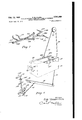
- Fig. 1 is a perspective view of the bottle unloading machine, showing the bottle carrying cradle partly inverted, and illustrating a section of the endless bottle conveyer chain of the conventional bottle washing machine, and details of the mechanism for driving the unloading mechanism.
- Fig. 2 is a perspective view, showing the vertical slides for the cradle support, one of the 2 horizontal tracks, and the means for elevating and lowering this track and the cradle.
- Fig. 3 is a perspective view, showing the combined vertical slides and horizontal slides for cradle support, and the means for shifting the cradle support longitudinally in the direction of the length of the bottle conveyer chain.
- Fig. 4 is a detail view, taken on line 4-4 of Fig. 3, showing the lever for shifting the cradle support laterally of the bottle conveyer chain, also showing certain parts in section.
- Fig. 5 is an exploded perspective view, showing the main cam shafts, the driving gears for operating the same, and the lateral shifting lever, and its rock shaft.
- Fig. 6 is a perspective view, showing the mechanism for inverting the bottle container to discharge its load.
- Fig. '7 is a perspective view, showing a fragmentary detail of the means employed for releasing the bottles of any group of bottles arranged in the container.
- Fig. 8 is a plan view of the container, indicating the position and action of the bottle releasingmeans.
- Fig. 9 is a vertical sectional view, taken on line 9-4 of Fig. 8, looking inthe direction of the arrows.
- Fig. 10 is an end elevation of the bottle container, shown partly in section, and illustrating the manual efiort of unloading a commercial box or container, so that the machine container will be loaded with its bottles.
- Fig. 11 is a vertical sectional view through the machine container, showing the discharging action of one of the bottle groups into the receiving sockets of the endless conveyer chain of the bottle washing machine.
- 5 designates a pair of spaced vertical frame supports which are suitably mounted on the frame of the conventional bottle washing machine 6, which includes the horizontally traveling endless conveyer chain 1, which is provided with a series of vertical sockets 8, formed on the chain links which are pivotally connected, as by the pins
- the endless conveyer chain 1 travels continuously in a horizontal plane to carry bottles to be washed through the washing cycle, and it is necessary to deposit the bottles necks downwardly into the holding vertical sockets 8, so that water may be forced, together with the usual cleansing charges, into the bottles, and then allowed to side plates 2
- each conveyor chain I can be operated by any mechanismadapted for the driving of such conveyors andforms a part of .the washing machine 5.
- the speed of movement ofthe chain will be slow to allow for the movements of the operator of the bottle loader.
- the vertical frame supports are connected to each other by means of cross bars II and I2, the cross bar 12 being disposed above the cross bar I, and offset from the vertical plane of the cross bar II, by the offset portions 5a of the vertical frame supports 5.
- Horizontal frame supporting bars I 3 and Marc connected to the vertical frame supports or uprights 5', and are provided with braces l5 and I6 to stiffen-the frame thus built up.
- the outer end of the bar I3 is disposed at right angles at
- the bar I3 is also supported at its outer endby the vertical frame bar I6, and the bar I4 is supported by the vertical frame bar II.
- a horizontalround'bar track I9 is supporte at one ⁇ end on the end
- a carriage having, side plates 2
- each side plate is progroup of four engaging the upper side of its round bar track and two engaging the lower side of the same track.
- a second carriage comprising the side plates 26 and 21, andthe end plates or bars 26 and 29,
- the sideplates 26'and- 2I carry bracket arms 33 and 34, which are of L-shaped form, and the lower and outerend'sof these bracket arms support a thrustplate 35, which is disposed in a vertical plane.
- the thrust plate serves to operate a long lever for the purpose hereinafter'mentionedr i 4 e v
- and 32 provide vertical tracks for the free turning rollers 36 and 31 carried by' the U-shaped cradle frame 36, Fig. 2, which includes a main frame section 39, and
- -upper horizontally projecting end arms 40 and The rollers '36 are' carried directly by a vertical bar 3611', attached to the main frame section 39, and the rollers 31 are carried by a vertical bar 31a also attached to the same main frame section.
- the cradle frame also carries lower horizontal arms 42 and'43, disposed in a common horizontal plane, and opposite to each other.
- are supported on the hanger bars 44 and 45, Fig. 2, which depend from the cross bar or carriage 46, which is provided with grooved rollers or wheels 41 and 48, pivoted to turn thereon, against the horizontal track 49, which is suspended by its central arm 50 from the hook 5
- a rocker frame 66 is pivotally supported by the pins 61, which extend through short arms 63 of the rocker frame.
- This frame is rectangular in shape'so as to receive a.- handling container or receptacle 69, Fig. 1.
- One side bar 66a of the rocker frame 66 is provided with a lug 66b, Figs. 1 and 6, to which cable I9 is connected.
- This cable travels onthe pulley II, and is connected to lever I2, which is pivoted on a shaft 13 fixed upon the machine base frame 5a in any suitable rnanner, and connected by the chain I4 with a rocker I5 for the purpose to be hereinafter set forth.
- is mounted on the upper cross bar l2 of the frame.
- the cross bar I2 also carries the pulley 54 of the cable 53, and a pulley 55 for the same cable, which is mounted to turn in axially centered position with the pulley I c
- the cam carrying shaft 64 is mounted to turn in bearings I6 on base frame 5a, and is provided with a bevel end gear 11, Figs. land 5, which has driving engagement with bevel gear I6, on shaft I9, which is mounted to turn'in bearings 80.
- the shaft I9 is equipped with an end bevel gear 8
- the shaft- 331s equipped with another end bevel gear 85, which has driving engagement with the bevel gear 66,on the vertical shaft 31, which is provided with a sprocket 86, engaged by driving conveyor chain 69 of the washing machine conveyor I. Accordingly, driving mechanism is provided for the machine which in operation is responsive to the movement of the washing machine conveyor.
- the shaft 64 carries a cam which engages the follower roller 9
- the upper end of this lever 92 is equipped with an arm-94 which carries a roller 95, which engages the thrust plate 35.
- the function of the lever 92 is to produce a longitudinal movement of the laterally shiftable carriage which includes the side plates 26 and 21, on the horizontal bar tracks 23 and 24.. This causes the container 69 to move with the conveyor I while bottles are being transferred to the vertical conveyor sockets 3.
- and 22 are connected to each other by means of a twisted bar 2 Ia, Fig. 5, which is engaged by the upper end of the lever 96, the
- This shaft 91 carries alever arm 99, which is provided with a cam follower roller I00,
- lever 96 is provided with a hook bend 961: so that it will slightly overhang the cross bar 2Ia.
- a coil spring I92 is connected at one end to the cross bar 2Ia and at the other end to an arm I92a carried by the frame, so that a pulling effort will be made on the side plates 2
- the frame having the plates 2I and 22 will, through the lever 96, be moved toward the operator in timed relation to the conveyor.
- the shaft 19 carries a cam I99 which engages the cam follower roller I94 on the lever I95. Figs. and 6, which rocks on the shaft I96.
- the lower end of this lever is pivotally connected with the link I91, which is pivotally connected with the rocker I5, which is mounted on the shaft I96 pivoted on base frame 5a. shown in detail in perspective in Fig. 6.
- the handling container 69 shown in Figs. 8, 9, and 11, is positioned in the cradle frame 66, as indicated in Fig. 10.
- This handling container is provided with four parallel rows of bottle guiding passages or sockets H9, which are open at both ends.
- the individual sockets or passages of one row is disposed in staggered relation to the passages or sockets of the adjacent row, as shown in Fig. 8 for alignment with the respective staggered sockets of the conveyor.
- the handling container 69 is loaded by inverting a commercial carrier container or box, indicated at B in Fig. 10, so that the twenty-four bottles of this box will be discharged by gravity into the handling container 69.
- Discharge of the bottles which are disposed in the handling container 69 is controlled by means of a series of arcuate gripping jaws III and H2.
- the jaws I I I are carried by a rod or bar I I3, and the jaws H2 are carried by the rod or bar I I4, as shown in Fig. '7.
- the rod or bar I I3 is pivotally connected with the link H5 and the rod or bar H4 is pivotally connected with the link H6.
- These two links are pivotally connected with the lever arms H1 of the T-shaped lever H8, which is pivoted midway of the ends of the lever arms I I1, and provided with a long lever arm I I8a, the outer end of which is equipped with an abutment bar H9.
- the bottles in two adjacent rows of passages, numbering 12 bottles in all, are discharged at one time, and then the bottles in the adjacent twin rows are discharged at one time.
- the discharge in each case is made directly into the open vertical sockets of the endless washer chain 1, as indicated in Fig. 9.
- the timing of the discharge of the first and second dozen group of bottles, and the shifting of the handling container 69 is controlled by the movement of the different cams, in synchronism with the movement of the endless conveyer washer chain I, through the driving mechanism shown in Fig. 5.
- the abutment bar I I9 of each T-shaped lever H9 is engaged by an abutment bar I29 mounted on the frame of the machine. and disposed in the path of the abutment bar I I9.
- the handling container 69 is engaged by a coil spring I2I, which acts to return the container to its original position.
- the handling container 69 is supported so that the loading side of the same will be exposed in an inclined plane.
- the case or box of empty beverage or other bottles is then placed against the open upper side of the handling container 69 in an inverted manner and the bottles from the case or box are transferred to the container 69.
- passages of this container are spaced apart on centers which will correspond to the center spacing of the vertical sockets 9 of the conveyerwashor chain 1.
- the next step or operation is to invert the container 69, so that the first dozen of empty beverage bottles are discharged to the receiving sockets 8 of the conveyer washer chain.
- the next step or operation is to cause the container 69 to rise so that it does not interfere with the movement of the conveyer washer chain 1. and all bottles of the first dozen group will be freed from the handling container 69.
- the next step is to shift the container 69 so that the second dozen bottle group will be, moved into position for loading the conveyer washer chain, after which the container 69 is elevated and returned to its initial position.
- All of the various devices for the movement of the receptacle to align the same with the conveyor sockets is effected automatically in sequence and in response to the movement of the conveyor chain and in timed relation therewith.
- the cam 63 of the mechanism will raise and lower the cradle frame 38.
- Cam 63 is So shaped to provide this movement at the proper time and at the proper speed.
- Cam I93 acting upon lever I95 will cause the cradle frame to be inverted so that the bottom openings of the receptacle retained by the cradle frame will be in vertical registration with the conveyor sockets. Only two rows at a time of these openings become so aligned upon the initial inverting of the cradle and its receptacle.
- Cam 99 will accordingly cause the shifting movement of the cradle and the receptacle in the direction of movement of the conveyor and to travel for a short distance with the same.
- the rods H9 for one pair of rows will be operated by the engagement with the abutment I29 so as to effect the discharge of the bottles to the conveyor sockets.
- the cradle and the receptacle are allowed to return as effected by the cam 99 and the cam I9I will so act upon the lever 96 to adjust the cradle toward the operator so that the second two rows of the bottles of the receptacle can be aligned with the conveyor chain. Thereafter.
- the cam 99 will again act to cause the movement of the cradle and the receptacle in the direction of the conveyor and thereafter the next rod H9 will engage the abutment I29 to release the next two rows of the bottles from the receptacle. Thereafter the cradle and the receptacle can be raised and the cradle uprighted all through the action of the cams to permit the next loading of bottles thereinto. Automatically the mechanism will go through the sam steps again to discharge the 'new set of bottles which have been loaded into the receptacle. The operation is continuous and is in timed relation to the washer conveyor chain.
- the unloading machine may be used in connection with any traveling washer chain, and may be adapted for handling any type of bottles, whether used for beverages. milk or other fluids.
- an endless conveyer chain having a series of vertical bottle holding sockets
- an unloader for automatically loading the sockets with inverted bottles to be washed
- means operated by the conveyer chain for raising and lowering the unloader, means coacting therewith for releasing bottles from the unloader, means coacting therewith for inverting the unloader.
- means disposed in the path of the unloader for actuating said releasing means, and means for shifting the unloader inthe direction of the travel of the endless conveyer chain.
- an endless traveling bottle washing conveyer chain having a series of links each of which is provided with a vertical bottle holding socket, a receptacle supported over the conveyer chain for pivotal movement, means for movin the receptacle in the direction or travel of the conveyer chain, means operated from the conveyer chain for inverting the receptacle, and means coacting with the chain operated means for releasing bottles from the receptacle to the sockets of th conveyer chain.
- a cradle supported above the conveyer, a receptacle pivotally supported on the cradle, means for raising and lowering the cradle and the receptacle, oppositely moving releasing elements carried by the receptacle for releasing bottles 6 from one side of the receptacle, means for inverting the cradle and its receptacle, and means for operating the elements.
Description
Feb. 13, 1951 M. CLARK 2,541,809
QUANTITY BOTTLE LOADER FpR AUTOMATIC BEVERAGE BOTTLE WASHING MACHINES Filed Sept. 5, 1947 k 7 Sheets-Sheet 1 INVENTOR. 425 Mwzmv (zAzzK ATTOJEMY Feb; 13, 1951 E. M. CLARK 2,541,309
' QUANTITY BOTTLE LOADER FOR AUTOMATIC BEVERAGE BOTTLE'WASHING MACHINES.
Filed Sept. 5, 1947 7 Sheets-Sheet 2 IN VEN TOR.
Z m MAUPJGE (LA/PK Feb. 13, 1951 E. M. CLARK 2,541,809
QUANTITY BOTTLE LOADER FOR AUTOMATIC BEVERAGE BOTTLE WASHING MACHINES '7 Sheets-Sheet 5 Filed Sept. 5, 1947 INVENTOR. E4131? JIAZZIZICE CLARK ATTORNEY E. M. CLAIK 01m: LOADER FOR AUT OMATIC BEVERAGE Feb. 13, 1951 QUANTITY B BOTTLEYWAS HING MACHINES 7 Sheets-Sheet 4 Filed Sept. 5. 1947 r uvwvrox m1 MWICI 62.4131? Feb. 13, 1951 M CLARK 2,541,809
QUANTITY BOTTLE LABER FOR AUTOMATIC BEVERAGE BOTTLE WASHING MACHINES- Sheets-Sheet 5 Filed Sept. 5, 1947 IN VEN TOR.
EARL mumm CLARK ATTORNEY Feb. 13, 1951 E M CLARK A 2,541,809
QUANTITY BOTTLE LEADER FOR AUTOMATIC BEVERAGE BOTTLE WASHING MACHINES 7 Sheets-Sheet 6 Filed Sept. 5, 1947 INVENTOR. 14m MAURICE CLARK ATTORNEY E. M. CLARK ITY BOTTLE LOADER FOR AUTOM Feb. 13, 1951 QUANT ATIC BEVERAGE BOTTLE WASHING MACHINES Filed Sept. 5, 1947 7 Sheets-Sheet 7 INVENTOR. EARL MUBICE CLARK llifl I llillllrlll u- I Illll'flll Patented Feb. 13, 1951 QUANTITY BOTTLE LOADER FOR AUTO- MATIC. BEVERAGE BOTTLE WASHING MACHINES Earl Maurice Clark, Kalispell, Mont., assignor of twenty-five per cent to Lee J Lewis and twentyflve per cent to M. R. Johnson, both of Kalispell,
Mont.
Application September 5, 1947, Serial No. 772,333
8 Claims. 1
This invention relates to an improved machine for loading beverage bottles into beverage bottle washing machines, of the type which employs an endless carrier chain moving in an approximate horizontal plane, and generally known to the trade as Miller hydro bottle washers.
One of the objects of the invention is to provide an attachment for an automatic beverage bottle washing machine, which includes a cradle for receiving a dozen or more beverage bottles to be washed, means for inverting the cradle to deposit the bottles in groups of a dozen or a fixed number, and means for moving the cradle with its load of bottles in synchronism with the movement of the endless bottle washing chain, to permit of the discharge of the bottles into the receiving sockets or cups of the endless bottle washing chain conveyer.
Another object of the invention is the provision of a loading attachment for endless bottle washing conveyer chains, by means of which beverage bottles may be automatically unloaded from a commercial receptacle to the receiving cups or sockets of the endless chain and the operation repeated indefinitely.
Another object of the invention is to provide a cradle for the bottles to be loaded onto the endless conveyer chain which can hold two equal groups of beverage or other bottles to be washed, with means for inverting the cradle to dumping position, means for releasing one of the bottle groups to load the endless chain bottle washing conveyer, and means for shifting the cradle with reference to the conveyer chain, and for automatically releasing the second group of bottles to the conveyer chain, and means for returning the cradle to initial position to receive another load of two equal groups of beverage bottles to be washed.
With the above and other objects in view the invention comprises certain new and useful constructions, combinations and arrangements of parts, clearly described in the following specification, and fully illustrated in the drawings, in which:
Fig. 1 is a perspective view of the bottle unloading machine, showing the bottle carrying cradle partly inverted, and illustrating a section of the endless bottle conveyer chain of the conventional bottle washing machine, and details of the mechanism for driving the unloading mechanism.
Fig. 2 is a perspective view, showing the vertical slides for the cradle support, one of the 2 horizontal tracks, and the means for elevating and lowering this track and the cradle.
Fig. 3 is a perspective view, showing the combined vertical slides and horizontal slides for cradle support, and the means for shifting the cradle support longitudinally in the direction of the length of the bottle conveyer chain.
Fig. 4 is a detail view, taken on line 4-4 of Fig. 3, showing the lever for shifting the cradle support laterally of the bottle conveyer chain, also showing certain parts in section.
Fig. 5 is an exploded perspective view, showing the main cam shafts, the driving gears for operating the same, and the lateral shifting lever, and its rock shaft.
Fig. 6 is a perspective view, showing the mechanism for inverting the bottle container to discharge its load.
Fig. '7 is a perspective view, showing a fragmentary detail of the means employed for releasing the bottles of any group of bottles arranged in the container.
Fig. 8 is a plan view of the container, indicating the position and action of the bottle releasingmeans.
Fig. 9 is a vertical sectional view, taken on line 9-4 of Fig. 8, looking inthe direction of the arrows.
Fig. 10 is an end elevation of the bottle container, shown partly in section, and illustrating the manual efiort of unloading a commercial box or container, so that the machine container will be loaded with its bottles.
Fig. 11 is a vertical sectional view through the machine container, showing the discharging action of one of the bottle groups into the receiving sockets of the endless conveyer chain of the bottle washing machine.
Referring to the drawings, which illustrate the practical embodiment of the invention, 5 designates a pair of spaced vertical frame supports which are suitably mounted on the frame of the conventional bottle washing machine 6, which includes the horizontally traveling endless conveyer chain 1, which is provided with a series of vertical sockets 8, formed on the chain links which are pivotally connected, as by the pins The endless conveyer chain 1 travels continuously in a horizontal plane to carry bottles to be washed through the washing cycle, and it is necessary to deposit the bottles necks downwardly into the holding vertical sockets 8, so that water may be forced, together with the usual cleansing charges, into the bottles, and then allowed to side plates 2|;and 22. V vided with four such grooved rollers, two of each conveyor chain I can be operated by any mechanismadapted for the driving of such conveyors andforms a part of .the washing machine 5. The speed of movement ofthe chain will be slow to allow for the movements of the operator of the bottle loader. p
The vertical frame supports are connected to each other by means of cross bars II and I2, the cross bar 12 being disposed above the cross bar I, and offset from the vertical plane of the cross bar II, by the offset portions 5a of the vertical frame supports 5. v
Horizontal frame supporting bars I 3 and Marc connected to the vertical frame supports or uprights 5', and are provided with braces l5 and I6 to stiffen-the frame thus built up. The outer end of the bar I3 is disposed at right angles at |3a to itself, and the outer end of thebar,|4 is .disposed at right angles |4a to itself. The bar I3 is also supported at its outer endby the vertical frame bar I6, and the bar I4 is supported by the vertical frame bar II. A horizontalround'bar track I9 is supporte at one} end on the end |3 a of the bar I3, and at the other end on the arm I9a, carried by the adbar 5. Thesetwo bar tracks I9 and are disposedina common horizontal plane.
A carriage having, side plates 2| and 22, and
- the roundbar tracks 23 and 24, is slidably supported on the track bars I9 and 20, by means of the grooved rollers 25, 'pivotally supported on the Each side plate is progroup of four engaging the upper side of its round bar track and two engaging the lower side of the same track.
On the round bar horizontal tracks 23 and 24 a second carriage, comprising the side plates 26 and 21, andthe end plates or bars 26 and 29,
which rigidly connect the side plates 26 and 21 7. positions withinthe sockets by set screws 29?).
The sideplates 26'and- 2I carry bracket arms 33 and 34, which are of L-shaped form, and the lower and outerend'sof these bracket arms support a thrustplate 35, which is disposed in a vertical plane. The thrust plate serves to operate a long lever for the purpose hereinafter'mentionedr i 4 e v Thevertical rodsf3| and 32 provide vertical tracks for the free turning rollers 36 and 31 carried by' the U-shaped cradle frame 36, Fig. 2, which includes a main frame section 39, and
. -upper horizontally projecting end arms 40 and The rollers '36 are' carried directly by a vertical bar 3611', attached to the main frame section 39, and the rollers 31 are carried by a vertical bar 31a also attached to the same main frame section. The cradle frame also carries lower horizontal arms 42 and'43, disposed in a common horizontal plane, and opposite to each other.
The outer ends of the horizontal arms 40 and 4| are supported on the hanger bars 44 and 45, Fig. 2, which depend from the cross bar or carriage 46, which is provided with grooved rollers or wheels 41 and 48, pivoted to turn thereon, against the horizontal track 49, which is suspended by its central arm 50 from the hook 5|,
which is carried by turn buckle 52, supported on the steel cable 53, Figs. 1 and 2, which operates over the pulleys 54; 55,56, 51, and 58, and which is connected by its lower end to lever 59, pivoted at 60, and provided with a short arm 6|. which carries a cam follower roller 62, which engages motion transferring and timing cam 63, mounted on the shaft 64. A weight 65 is ad- Justable on the lever 59. This arrangement, as the cam 63 is rotated vertically, adjusts the cradle frame 33 on the vertical rods 3| and 32 by the lifting and lowering of the track 49.
On the outer ends of the lower horizontal arms 42 and 43 a rocker frame 66 is pivotally supported by the pins 61, which extend through short arms 63 of the rocker frame. This frame is rectangular in shape'so as to receive a.- handling container or receptacle 69, Fig. 1. One side bar 66a of the rocker frame 66 is provided with a lug 66b, Figs. 1 and 6, to which cable I9 is connected. This cable travels onthe pulley II, and is connected to lever I2, which is pivoted on a shaft 13 fixed upon the machine base frame 5a in any suitable rnanner, and connected by the chain I4 with a rocker I5 for the purpose to be hereinafter set forth. The cable pulley 1| is mounted on the upper cross bar l2 of the frame. a
The cross bar I2 also carries the pulley 54 of the cable 53, and a pulley 55 for the same cable, which is mounted to turn in axially centered position with the pulley I c The cam carrying shaft 64 is mounted to turn in bearings I6 on base frame 5a, and is provided with a bevel end gear 11, Figs. land 5, which has driving engagement with bevel gear I6, on shaft I9, which is mounted to turn'in bearings 80. The shaft I9 is equipped with an end bevel gear 8|, which has driving engagement with the gevel gear 82 onshaft 33, which is mounted to turn inbearings 64. The shaft- 331s equipped with another end bevel gear 85, which has driving engagement with the bevel gear 66,on the vertical shaft 31, which is provided with a sprocket 86, engaged by driving conveyor chain 69 of the washing machine conveyor I. Accordingly, driving mechanism is provided for the machine which in operation is responsive to the movement of the washing machine conveyor.
The shaft 64 carries a cam which engages the follower roller 9| on the lever 92, which is mounted to rock on the shaft 93 carried on the machine base, Figs. 1 and 3. The upper end of this lever 92 is equipped with an arm-94 which carries a roller 95, which engages the thrust plate 35. The function of the lever 92 is to produce a longitudinal movement of the laterally shiftable carriage which includes the side plates 26 and 21, on the horizontal bar tracks 23 and 24.. This causes the container 69 to move with the conveyor I while bottles are being transferred to the vertical conveyor sockets 3. v
The side plates 2| and 22 are connected to each other by means of a twisted bar 2 Ia, Fig. 5, which is engaged by the upper end of the lever 96, the
lower end of which is mounted to rock on the shaft 91, supported in the bearings 96 on the base frame-5a. This shaft 91 carries alever arm 99, which is provided with a cam follower roller I00,
7 which engages the cam III I, on the shaft I9. The
upper end of the lever 96 is provided with a hook bend 961: so that it will slightly overhang the cross bar 2Ia. A coil spring I92 is connected at one end to the cross bar 2Ia and at the other end to an arm I92a carried by the frame, so that a pulling effort will be made on the side plates 2| and 22 to return them to the initial position after the shifting action imposed by the operation of the lever 96. The frame having the plates 2I and 22 will, through the lever 96, be moved toward the operator in timed relation to the conveyor.
The shaft 19 carries a cam I99 which engages the cam follower roller I94 on the lever I95. Figs. and 6, which rocks on the shaft I96. The lower end of this lever is pivotally connected with the link I91, which is pivotally connected with the rocker I5, which is mounted on the shaft I96 pivoted on base frame 5a. shown in detail in perspective in Fig. 6.
The handling container 69, shown in Figs. 8, 9, and 11, is positioned in the cradle frame 66, as indicated in Fig. 10. This handling container is provided with four parallel rows of bottle guiding passages or sockets H9, which are open at both ends. The individual sockets or passages of one row is disposed in staggered relation to the passages or sockets of the adjacent row, as shown in Fig. 8 for alignment with the respective staggered sockets of the conveyor.
The handling container 69 is loaded by inverting a commercial carrier container or box, indicated at B in Fig. 10, so that the twenty-four bottles of this box will be discharged by gravity into the handling container 69.
Discharge of the bottles which are disposed in the handling container 69 is controlled by means of a series of arcuate gripping jaws III and H2. The jaws I I I are carried by a rod or bar I I3, and the jaws H2 are carried by the rod or bar I I4, as shown in Fig. '7. The rod or bar I I3 is pivotally connected with the link H5 and the rod or bar H4 is pivotally connected with the link H6. These two links are pivotally connected with the lever arms H1 of the T-shaped lever H8, which is pivoted midway of the ends of the lever arms I I1, and provided with a long lever arm I I8a, the outer end of which is equipped with an abutment bar H9. Under each of the four rows of six bottle passages a pair of these rods or bars and gripping jaws is arranged. These jaws are moved toward each other as shown in Fig. 8, and away from each other by rocking the T-shaped lever H8, so that the companion jaws of each pair of jaws will be simultaneously moved toward and away from each other.
The bottles in two adjacent rows of passages, numbering 12 bottles in all, are discharged at one time, and then the bottles in the adjacent twin rows are discharged at one time. The discharge in each case is made directly into the open vertical sockets of the endless washer chain 1, as indicated in Fig. 9.
The timing of the discharge of the first and second dozen group of bottles, and the shifting of the handling container 69 is controlled by the movement of the different cams, in synchronism with the movement of the endless conveyer washer chain I, through the driving mechanism shown in Fig. 5. The abutment bar I I9 of each T-shaped lever H9 is engaged by an abutment bar I29 mounted on the frame of the machine. and disposed in the path of the abutment bar I I9. The handling container 69 is engaged by a coil spring I2I, which acts to return the container to its original position.
At the start of the cycle of operations, the handling container 69 is supported so that the loading side of the same will be exposed in an inclined plane. The case or box of empty beverage or other bottles is then placed against the open upper side of the handling container 69 in an inverted manner and the bottles from the case or box are transferred to the container 69. The
passages of this container are spaced apart on centers which will correspond to the center spacing of the vertical sockets 9 of the conveyerwashor chain 1.
The next step or operation is to invert the container 69, so that the first dozen of empty beverage bottles are discharged to the receiving sockets 8 of the conveyer washer chain. The next step or operation is to cause the container 69 to rise so that it does not interfere with the movement of the conveyer washer chain 1. and all bottles of the first dozen group will be freed from the handling container 69. The next step is to shift the container 69 so that the second dozen bottle group will be, moved into position for loading the conveyer washer chain, after which the container 69 is elevated and returned to its initial position.
All of the various devices for the movement of the receptacle to align the same with the conveyor sockets is effected automatically in sequence and in response to the movement of the conveyor chain and in timed relation therewith. The cam 63 of the mechanism will raise and lower the cradle frame 38. Cam 63 is So shaped to provide this movement at the proper time and at the proper speed. Cam I93 acting upon lever I95 will cause the cradle frame to be inverted so that the bottom openings of the receptacle retained by the cradle frame will be in vertical registration with the conveyor sockets. Only two rows at a time of these openings become so aligned upon the initial inverting of the cradle and its receptacle.
Cam 99 will accordingly cause the shifting movement of the cradle and the receptacle in the direction of movement of the conveyor and to travel for a short distance with the same. At the end of the stroke, the rods H9 for one pair of rows will be operated by the engagement with the abutment I29 so as to effect the discharge of the bottles to the conveyor sockets. Thereafter, the cradle and the receptacle are allowed to return as effected by the cam 99 and the cam I9I will so act upon the lever 96 to adjust the cradle toward the operator so that the second two rows of the bottles of the receptacle can be aligned with the conveyor chain. Thereafter. the cam 99 will again act to cause the movement of the cradle and the receptacle in the direction of the conveyor and thereafter the next rod H9 will engage the abutment I29 to release the next two rows of the bottles from the receptacle. Thereafter the cradle and the receptacle can be raised and the cradle uprighted all through the action of the cams to permit the next loading of bottles thereinto. Automatically the mechanism will go through the sam steps again to discharge the 'new set of bottles which have been loaded into the receptacle. The operation is continuous and is in timed relation to the washer conveyor chain.
It is understood that the unloading machine may be used in connection with any traveling washer chain, and may be adapted for handling any type of bottles, whether used for beverages. milk or other fluids.
It is also understood that various changes in the details of construction, their combination,
and arrangement, may be made in carrying .out the invention, as defined in the claims hereof.
Having described the invention, I claim as new:
1. In combination, an endless conveyer chain having a series of vertical bottle holding sockets, an unloader for automatically loading the sockets with inverted bottles to be washed, means operated by the conveyer chain for raising and lowering the unloader, means coacting therewith for releasing bottles from the unloader, means coacting therewith for inverting the unloader. means disposed in the path of the unloader for actuating said releasing means, and means for shifting the unloader inthe direction of the travel of the endless conveyer chain.
2. In combination, an endless traveling bottle washing conveyer chain having a series of links each of which is provided with a vertical bottle holding socket, a receptacle supported over the conveyer chain for pivotal movement, means for movin the receptacle in the direction or travel of the conveyer chain, means operated from the conveyer chain for inverting the receptacle, and means coacting with the chain operated means for releasing bottles from the receptacle to the sockets of th conveyer chain.
3. The combination with a, traveling endless bottle washer conveyer, of a cradle mounted to rock above the conveyer, a receptacle having a series of bottle holding passages opening on opposite sides of the receptacle mounted on the cradle, means operated by the conveyer for shifting the cradle and the receptacle in the direction of the movement of the conveyer, releasing means carried by the cradle for releasing bottles from the receptacle, means for raising and lowering the cradle and the receptacle, means for inverting the cradle and the receptacle to cause bottles held thereby to be held in position to be discharged to the conveyer, and means disposed in the path of the cradle and receptacle for releasing bottles on the invertion of the cradle and the receptacle.
4. The combination with a traveling endless conveyer having vertical sockets for holding bottles to be washed, a cradle mounted over the conveyer for pivotal movement, a. receptacle supported on the cradle and provided with a series of passages each of which openson the top and bottom of the receptacle, means coacting with the conveyer for inverting the cradle and its receptacle, and means cooperating therewith for advancing the cradle and its receptacle in the general direction of the travel of the conveyer.
5. The combination with a traveling endless conveyer having vertical bottle holding sockets,
a cradle supported above the conveyer, a receptacle pivotally supported on the cradle, means for raising and lowering the cradle and the receptacle, oppositely moving releasing elements carried by the receptacle for releasing bottles 6 from one side of the receptacle, means for inverting the cradle and its receptacle, and means for operating the elements.
6. The combination with a traveling bottle washing conveyer, of a bottle loader associated with the conveyer and provided with a pivotally supported cradle, means for raising and lowering the cradle, means for shifting the cradle in the direction oi movement of the conveyer, means for shifting the cradle lateral to said direction of movement, means for inverting the cradle, a receptacle supported on the cradle, bottle releasing elements carried by the receptacle, means disposed in the path of the movement or the receptacle and cradle for operating said release elements, and means synchronized with the movement of the conveyer for operating all of said means in timed relation to the movement or the conveyer, to cause said releasing elements to deposit bottles from the receptacle into the conveyer.
7. The combination with an endless traveling bottle washing conveyer having vertical bottle holding sockets therein, a, receptacle having transverse passages spaced to correspond with the spacing oi the conveyer sockets and opening from the opposite sides of the receptacle, means for tilting the receptacle above the conveyer, means for shifting the receptacle inthe direction of movement of the conveyer, means for shifting the receptacle in a, movement transverse to that of the conveyer, means for raising and lowering the receptacle, means for discharging a certain number of bottles loaded in the receptacle to the sockets oi the conveyer, and means for discharging the balance of the bottles loaded on the receptacle to the sockets of the conveyer.
8. The combination with an endless traveling bottle washer conveyer having vertical bottle holding sockets, a cradle, a receptacle having bottle holding passages pivotally supported on the cradle, a track 'on which the cradle slides, a, hoist for lowering and raising the track, means for shifting the receptacle in the direction of movement of the conveyer, means for shifting the receptacle in the direction at right angles to the movement of the conveyer, means for releasing certain bottles loaded on the receptacle and cradle, means for releasing the remaining bottles on the receptacle and cradle, and means operated in synchronism with the travel of the conveyer for operating all of said means to automatically transfer bottles from the receptacle to the sockets oi the conveyer.
EARL MAURICE CLARK.
REFERENCES CITED The following references are of record in the file of this patent:
UNITED STATES PATENTS Number Name Date 1,253,748 Tyson Jan; 15, 1918 1,651,925 Marsh Dec. 6, 1927 1,700,944 Loew Feb. 5, 1929 2,074,383 Funk Mar. 23, 1937 2,400,542 Davis May 21, 1946
Priority Applications (1)
| Application Number | Priority Date | Filing Date | Title |
|---|---|---|---|
| US772333A US2541809A (en) | 1947-09-05 | 1947-09-05 | Quantity bottle loader for automatic beverage bottle washing machines |
Applications Claiming Priority (1)
| Application Number | Priority Date | Filing Date | Title |
|---|---|---|---|
| US772333A US2541809A (en) | 1947-09-05 | 1947-09-05 | Quantity bottle loader for automatic beverage bottle washing machines |
Publications (1)
| Publication Number | Publication Date |
|---|---|
| US2541809A true US2541809A (en) | 1951-02-13 |
Family
ID=25094719
Family Applications (1)
| Application Number | Title | Priority Date | Filing Date |
|---|---|---|---|
| US772333A Expired - Lifetime US2541809A (en) | 1947-09-05 | 1947-09-05 | Quantity bottle loader for automatic beverage bottle washing machines |
Country Status (1)
| Country | Link |
|---|---|
| US (1) | US2541809A (en) |
Cited By (6)
| Publication number | Priority date | Publication date | Assignee | Title |
|---|---|---|---|---|
| US2712390A (en) * | 1951-02-10 | 1955-07-05 | Nat Can Corp | Machine for unloading cans from cartons |
| US2721016A (en) * | 1950-08-04 | 1955-10-18 | Dixon Engineering Company | Loading mechanism for frozen confection bagging machines |
| US2731127A (en) * | 1950-03-11 | 1956-01-17 | Allied Steel And Conveyors Inc | Conveyor transfer mechanism |
| US2934195A (en) * | 1954-07-30 | 1960-04-26 | Mechanical Handling Sys Inc | Work handling and transfer systems |
| DE3301525A1 (en) * | 1983-01-19 | 1984-07-19 | Heinz Oberurnen Hartnig | CLEANING DEVICE FOR SINGLE-SIDED OPEN CONTAINERS |
| US4911602A (en) * | 1988-06-17 | 1990-03-27 | Kirin Beer Kabushiki Kaisha | Container supply system |
Citations (5)
| Publication number | Priority date | Publication date | Assignee | Title |
|---|---|---|---|---|
| US1253748A (en) * | 1916-03-20 | 1918-01-15 | Frank Tyson | Bottle-crate-emptying machine. |
| US1651925A (en) * | 1927-12-06 | Machine | ||
| US1700944A (en) * | 1926-08-06 | 1929-02-05 | Cleveland Trust Co | Bottle-cleaning apparatus |
| US2074383A (en) * | 1934-06-22 | 1937-03-23 | Globe Egg Stabilizing Company | Egg handling machine |
| US2400542A (en) * | 1942-12-30 | 1946-05-21 | Allan C Davis | Case unloading machine |
-
1947
- 1947-09-05 US US772333A patent/US2541809A/en not_active Expired - Lifetime
Patent Citations (5)
| Publication number | Priority date | Publication date | Assignee | Title |
|---|---|---|---|---|
| US1651925A (en) * | 1927-12-06 | Machine | ||
| US1253748A (en) * | 1916-03-20 | 1918-01-15 | Frank Tyson | Bottle-crate-emptying machine. |
| US1700944A (en) * | 1926-08-06 | 1929-02-05 | Cleveland Trust Co | Bottle-cleaning apparatus |
| US2074383A (en) * | 1934-06-22 | 1937-03-23 | Globe Egg Stabilizing Company | Egg handling machine |
| US2400542A (en) * | 1942-12-30 | 1946-05-21 | Allan C Davis | Case unloading machine |
Cited By (7)
| Publication number | Priority date | Publication date | Assignee | Title |
|---|---|---|---|---|
| US2731127A (en) * | 1950-03-11 | 1956-01-17 | Allied Steel And Conveyors Inc | Conveyor transfer mechanism |
| US2721016A (en) * | 1950-08-04 | 1955-10-18 | Dixon Engineering Company | Loading mechanism for frozen confection bagging machines |
| US2712390A (en) * | 1951-02-10 | 1955-07-05 | Nat Can Corp | Machine for unloading cans from cartons |
| US2934195A (en) * | 1954-07-30 | 1960-04-26 | Mechanical Handling Sys Inc | Work handling and transfer systems |
| DE3301525A1 (en) * | 1983-01-19 | 1984-07-19 | Heinz Oberurnen Hartnig | CLEANING DEVICE FOR SINGLE-SIDED OPEN CONTAINERS |
| US4911602A (en) * | 1988-06-17 | 1990-03-27 | Kirin Beer Kabushiki Kaisha | Container supply system |
| AU611299B2 (en) * | 1988-06-17 | 1991-06-06 | Kirin Beer Kabushiki Kaisha | Container supply system |
Similar Documents
| Publication | Publication Date | Title |
|---|---|---|
| US2611493A (en) | Device for transferring articles | |
| US3993189A (en) | Processing conveyor | |
| US3805943A (en) | Swivel-lift vacuum article loader | |
| US3458058A (en) | Stacking machine | |
| US3426922A (en) | Order picking mechanism | |
| US2541809A (en) | Quantity bottle loader for automatic beverage bottle washing machines | |
| US2692713A (en) | Casing machine | |
| US2119767A (en) | Crating apparatus | |
| US2738888A (en) | Processing machinery for electroplating and the like | |
| US2731146A (en) | Egg grading mechanism | |
| US2341606A (en) | Electroprocessing machine | |
| US2555227A (en) | Article handling apparatus | |
| US1382144A (en) | Conveying mechanism | |
| US2902181A (en) | Apparatus for performing treatment operations on workpieces | |
| ES8203304A1 (en) | Machine for filling or emptying containers used for the transport of arranged articles. | |
| US3072266A (en) | Material handling apparatus | |
| US2038458A (en) | Weighing mechanism | |
| US1510096A (en) | Automatic bottle unloader | |
| US1967213A (en) | Conveyer loading device | |
| US2438050A (en) | Bottle decapping and pouring mechanism for vending machines | |
| US2838896A (en) | Case loader | |
| US3033387A (en) | Article transferring apparatus | |
| US3125134A (en) | Machine for | |
| US2933212A (en) | Processing machine with individual elevators | |
| US3017010A (en) | Apparatus for transferring objects between conveyors |