US2540270A - Combined storm and screen window unit - Google Patents
Combined storm and screen window unit Download PDFInfo
- Publication number
- US2540270A US2540270A US707111A US70711146A US2540270A US 2540270 A US2540270 A US 2540270A US 707111 A US707111 A US 707111A US 70711146 A US70711146 A US 70711146A US 2540270 A US2540270 A US 2540270A
- Authority
- US
- United States
- Prior art keywords
- sheet
- storm
- roller
- window
- unit
- Prior art date
- Legal status (The legal status is an assumption and is not a legal conclusion. Google has not performed a legal analysis and makes no representation as to the accuracy of the status listed.)
- Expired - Lifetime
Links
- 238000007789 sealing Methods 0.000 description 4
- 239000000463 material Substances 0.000 description 3
- 238000004140 cleaning Methods 0.000 description 2
- 238000010276 construction Methods 0.000 description 2
- 238000009423 ventilation Methods 0.000 description 2
- 238000005406 washing Methods 0.000 description 2
- RYGMFSIKBFXOCR-UHFFFAOYSA-N Copper Chemical compound [Cu] RYGMFSIKBFXOCR-UHFFFAOYSA-N 0.000 description 1
- 241000292569 Pegusa lascaris Species 0.000 description 1
- 241000120694 Thestor Species 0.000 description 1
- -1 as felt and the like Substances 0.000 description 1
- 239000004744 fabric Substances 0.000 description 1
- 238000000034 method Methods 0.000 description 1
- 239000000203 mixture Substances 0.000 description 1
- 239000003973 paint Substances 0.000 description 1
- 239000004576 sand Substances 0.000 description 1
- XLYOFNOQVPJJNP-UHFFFAOYSA-N water Substances O XLYOFNOQVPJJNP-UHFFFAOYSA-N 0.000 description 1
Images


Classifications
-
- E—FIXED CONSTRUCTIONS
- E06—DOORS, WINDOWS, SHUTTERS, OR ROLLER BLINDS IN GENERAL; LADDERS
- E06B—FIXED OR MOVABLE CLOSURES FOR OPENINGS IN BUILDINGS, VEHICLES, FENCES OR LIKE ENCLOSURES IN GENERAL, e.g. DOORS, WINDOWS, BLINDS, GATES
- E06B9/00—Screening or protective devices for wall or similar openings, with or without operating or securing mechanisms; Closures of similar construction
- E06B9/52—Devices affording protection against insects, e.g. fly screens; Mesh windows for other purposes
- E06B9/54—Roller fly screens
Definitions
- the present invention relates to combined storm and screen window units adapted to be permanently associated with any standard, usual, or other type of window structures of buildings and the like.
- the present invention relates to a novel device which avoids the above referred to inconveniences and which, depending on the particular season existing, can be facilely operated to bring the storm or screen window part or pane into position to remain there until the season is over and such part operated into a nested and closed position'while the o.ther-part may be brought from its nested or closed lposition into its position of i-ntended utility, as across the sight or opening of the window.
- a -holder 1or fframee'like structure attached to the window structure, -as its frame, and'carries a roller or rollers of the usual vcurtain type roller upon which may 'be -rolled and from v'vs/"-li'ich may be unrolled -a ⁇ sheet-like material, such as a pliant or -iiexible transparent continuous non-perforate sheet .to serve -as-the storm windowpartlorpane, ora similar porous -or reticulated sheet to serve as ya screen, -with means to facilely engage the free end or border of the sheet with .a part of :the window structure for holding lthe sheet 'in extended condition, and also to have -a close or practically sealing relation to prevent :entry -of foreign material through the structure.
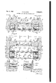
- Fig. 1 - is a view in elevation :of an Vvembodiment of 'the invention with a usual :type of window structure;
- Fig. 2 vis ya vertical sectional view l taken fin .a plane represented .by line 2.-2 in Fig. v1 of :the drawings;
- '3 is an enlarged horizontal Vsectional iview, with :parts ;broken;away. takenin a plane repre.- sented byline .f3-3 in Fig. :11 .fof the drawings;
- Fig. 4 is a similar View taken in a plane repre.- sented by line ll-s in. Fig. 1 of the drawings;
- Fig. 5 is a fragmentary longitudinal vertical central sectional view through one end of the up.- per roller housing and taken in a plane repre;- sented by line V5 5 in Fig. .4 of the drawings;
- Fig. 6 is a similar view at the other .end ⁇ of. the upper roller and taken in a plane represented by line l-6 in Fig; 4 of the drawings;
- Fig. 7 is a broken view similar to Fig. 2 on an enlarged scale
- Fig. 8 is a view of a detai-lvfeature used with the invention.
- Fig. 9 is .a view in elevation of an alternative embodiment of the invention.
- Fig. 10 is a vertical sectional view taken in'. .a yplane represented byline lli-I0 in Fig. 9 of' the drawings;
- Fig. V11. is a similar -view broken and en an enlarged scale
- Fig. 12 is a fragmentary horizontal sectional view, on yan enlarged scale,..taken ina plane ⁇ represented by line l2-.I2 in Fig. .9 of the .drawings with the screen fully extended; and,
- Fig. 13 is a similar fragmentary view .taken in a plane represented' 'by line
- a transverse roller box part 25 in which is rotatably supported a curtain type of roller 28 having the usual trunnions or the like 28 and 29 rotatable in saddle pieces 2l84 and 28a suitably fastened or secured to the ends of the roller box 2 (see Figs. 5 and 6)', and within which roller is a usual Acurtain roller spring 29 (see Fig. 7) and on which is wound a flexible transparent sheet 38 constituting the storm window pane or the like for the device, this sheet 38 being adapted to pass down through a slot or opening 3l provided in the bottom of the roller box 25.
- flanged parts 32 and 33 are flanged parts 32 and 33 (see Fig.
- sealing strips e and 35 such as brous material, as felt and the like, or rubber, or similar compositions, or the like, and which strips are held close together but to provide therebetween channels 38 and 9T along which the side border portions of the transparency 38 may sealingly slide, the strips 35 and 35 being suitably iixed, as adhering to the sides of the members 2l and 22, and the flanges 32 and 33, as shown in Figs. 3 and 4.
- the cross piece 38 (see Figs. 2 and 7) preferably forms a rigid or integral part of the roller box 2l, and in the event of desiring to remove the roller box 25, the screws 48 may be disconnected and the box 25 with the cross piece 38 accordingly removed, without disturbing the upright parts 2l and 22.
- the lower 'cross piece (see Fig. 7) has a flanged part 42 fitting on the sill 4 and secured thereto by suitable means, such as screws 53, and the upper portion of the Cross piece 59 has a lip M.
- a bar 45 bent to clamp the end of vthe sheet 39 (see Fig. 7) and held clamped by suitable means, such as screws d6.
- a linger-engaging strip il (see Figs. 7 and 8) which may be of angular form with a leg xed to the clamp bar 45' by the screws 138, and a lateral extended leg for engagement by the iingers of the user of the window device to open or close the storm sheet 39.
- a latch piece 48 having a leg secured, as by screws 49, to a leg of the bar or strip 4l (see Figs.
- the clamp member 45 (see Fig. 7) has an outer extending lip 55 for engaging with the lip at the lower end of the device (see Fig. 7) when the sheet 39 is fully extended.
- the device may have a bracing means, such as a strip or bar 55, adapted to abut the inner face of the storm' sheet 38 when it is in window closing condition, and as shown in the dotted line portion thereof in Fig. 7.
- This bar 55 has end legs 58 pivotally mounted on pivot screws 5'! secured to the upright members 2f and 22.
- limit stop elements 58 which may be in the form of screws secured to the upright members 2
- the invention also comprehends the provision of a porous flexible sheet, such as a screen 59, carried on a roller 58 rotatably supported in a roller box 6l seated on the sill 4 at the lower ends of the upright parts or posts B2 secured, as by screws 53, to the sides or stiles I and 2 of the window frame or casing.
- the roller B0 may be of a curtain roller type with a spring 64 in it and having trunnions 65 rotatable in brackets or saddles 68 xed at the ends of the box 5l.
- the box 6l has an opening or slot 61 through which the sheet 59 may pass when moving the sheet 59 to or from closing condition.
- a clamp bar or strip 88 so formed or bent as to clamp the end of the sheet 59, as shown in Fig. 7, and connected together and to the end of the sheet 59 by suitable means, such as screws or bolts 69.
- a nger-engaging piece or strip I0 is connected to the strip 68, connected, as by the screws 59, by which the sheet may be moved to or from closed position, as shown in Fig. 7.
- the strip 68 preferably has a lip 'H for engaging with a lip l2 of the cross piece or bar 13 extending between the sides l and 2 of the window structure and above the ends of the upright pieces or posts 62.
- This cross piece 'I2 may be attached to an upper part of the window structure, for full height of extension oi' the sheet 59, or, as shown in Fig. 7, to the lower sash rail or bar I8 of the upper sash, for a lesser height, by way of suitable securing elements, such as screws 14.
- the upright member 62 may have flanges 'l5 to provide, if desired, channel spaces for the disposition of sealing strips l5 and l1, such as felt or the like, between which the border or edge portions of the sheet 55 may slide when moved to and from closing position.
- the box 5I may have holes 'H8 for draining out any water that might enter the box 6I.
- a similar device is shown wherein the storm and screen sheets'or panes are mounted to be opened and closed transversely of the window structure in lieu of up and down. It comprises an attachable unit having transverse members 79 and 88 connected or secured respectively to the upper and lower frame pieces, as the lintel 3 and the sill 4, as shown in Fig. l1, by way of suitable securing elements, such as screws 8l and 82.
- roller boxes 83 and 89 Extending along the inside of the side parts l and 2 of the window frame or casing are disposed roller boxes 83 and 89 with the upper ends of these boxes abutting the lintel 3 and disposed at the ends of the cross piece or member 19, as also abutting the stops 'l' and l0, and with the roller ends of these boxes abutting or seating on the ledge or sill d and disposed at the ends of the cross piece or member 88, as also abutting these stops l.
- rollers 85 and 86 of the curtain roller type and having trunnions 8l and 88 rotatable in suitable brackets or saddles or the like 89 and 98 suitably secured to the end portions of the roller boxes 85 and 85.
- springs 9i and 92 as usual in this type of roller.
- the cross members 19 and 80" have flanges' 9i and 98 spaced from the' box of the' cross members to provide thin channels or the like 99' and for' holding sealing strips
- rollerboxes 83 and 84 are strips or bars
- 04 will form a rigid unitary structure adapted' as a unit to be applied to a Window frame or casing.
- will engage the catch
- This bar has end flanges
- the device is of unitary construction and may be attached as a unit to an existing window structure by simply inserting it in place and applying a few securing elements, such as screws. It takes the place of the usual storm windows and screens; it may be left in place permanently and it avoids the work of changing from one to the other at the change in seasons, and the attendant care of the stored storm window when the screens are in, and the like of the stored screens when the storm windows are in place.
- the storm sheet When it is desired to obtain ventilation the storm sheet will be drawn to the point desired to leave an opening beyond the free end of the storm sheet, and the screen sheet may or may not be drawn across the opening of the screen structure as may be desired.
- a combination storm and screen window unit for association with an existing window structure having a casing, comprising a frame structure having upright and transverse parts for abutting with parts of the window casing and for providing an opening in said unit, certain of said frame parts having means for attaching the unit to the window casing, and certain of said frame parts having a roller means, a sheet part wound on said roller means, and means attached to said sheet part by which the sheet part may be moved across the opening of the unit, and a bracing member carried by the frame of the unit and located adjacent the path of movement of the sheet part in the opening of the unit to brace 71- sad sheet part against bowing or warping, said bracing member having pivot means for pivotally supporting said bracing member in said frame of the unit.
- a combination storm Vand screen window unit for assocation with an existing Window structure having a casing comprising a frame structure having upright and transverse parts for abutting with parts of the window casing and for providing an opening in said unit, certain of said frame parts having means for attaching the unit to the window casing, and certain of said frameparts having a roller means, a sheet part wound on said roller means, and means'attached to said sheet part by which the sheet part may be moved across the opening of the unit, and a bracing member carried by the frame of the unit and located adjacent the path of movement of the sheet part in the opening of the unit to brace said sheet part against bowing or warping, said bracing member being pivotally supported in said 8, frame of the unit and being swing'able on' the support into contact with said sheet, and stops carried by the frame of the unit, to limit the swinging movements of the brace to the contact position.
Landscapes
- Engineering & Computer Science (AREA)
- Structural Engineering (AREA)
- Life Sciences & Earth Sciences (AREA)
- Insects & Arthropods (AREA)
- Pest Control & Pesticides (AREA)
- Architecture (AREA)
- Civil Engineering (AREA)
- Operating, Guiding And Securing Of Roll- Type Closing Members (AREA)
Description
6 Sheets-Sheet l P.: G. LUBER COMBINED STORM AND SCREEN WINDOW UNIT Feb. 69 1951 Filed Nov. 1, 1946 NWN Feb. I951 P. G. LUBER 2,540,27@
COMBINED STORM AND SCREEN WINDOW UNIT Y Filed Nov. l, 1946 e sheets-sheez Fe 6, i951 P. G. LUBER 2,540,270
COMBINED STORM AND SCREEN WINDOW UNIT Filed Nov. l, 1946 6 Sheets-Sheet 3 Feb, 6, 195i P. G. LUBER COMBINED STORM AND SCREEN WINDOW UNIT Filed Nov. l, 1946 6 Sheets-Sheet 4 Feb. 6, 1951 P Q LUBER 2,540,270
COMBINED STORM AND SCREEN WINDOW UNIT Filed Nov. l, 1946 6 Sheets-Sheet 6 Patented Feb. 6, 1951 UNITED STATES PATENT Phil G. Luber, Evanston, Ill.; Mary Agnes Luber, executrix of. said Phil G. Luber, deceased, as.- signor of one-half to Louis A. Bisson, lilvanstonl Ill.
Application November 1, 1946, Serial N o. 707,111
2 Claims. l
The present invention relates to combined storm and screen window units adapted to be permanently associated with any standard, usual, or other type of window structures of buildings and the like. y
It is the present custom at certain seasons of the year, as in the spring and fall, to attach to a window structure a screen or storm unit, respece tively, while at the same time removing the previous attached storm or screen units, respectively, and storing them until the following season arrivesl for reinstalling them. In the meanwhile, it is necessary to clean, paint, and other wise treat the units preparatory to the next installing of them.
The present invention relates to a novel device which avoids the above referred to inconveniences and which, depending on the particular season existing, can be facilely operated to bring the storm or screen window part or pane into position to remain there until the season is over and such part operated into a nested and closed position'while the o.ther-part may be brought from its nested or closed lposition into its position of i-ntended utility, as across the sight or opening of the window.
It comprises briefly of a -holder 1or fframee'like structure attached to the window structure, -as its frame, and'carries a roller or rollers of the usual vcurtain type roller upon which may 'be -rolled and from v'vs/"-li'ich may be unrolled -a `sheet-like material, such as a pliant or -iiexible transparent continuous non-perforate sheet .to serve -as-the storm windowpartlorpane, ora similar porous -or reticulated sheet to serve as ya screen, -with means to facilely engage the free end or border of the sheet with .a part of :the window structure for holding lthe sheet 'in extended condition, and also to have -a close or practically sealing relation to prevent :entry -of foreign material through the structure.
fOther objects, advantages, capabilities, @features, and fthe llike are comprehended'by the invention as will later appear, and as are inherently possessed by the invention.
.Referring fbrie'f-ly to the drawings:
Fig. 1 -is a view in elevation :of an Vvembodiment of 'the invention with a usual :type of window structure;
Fig. 2 vis ya vertical sectional view l taken fin .a plane represented .by line 2.-2 in Fig. v1 of :the drawings;
'3 is an enlarged horizontal Vsectional iview, with :parts ;broken;away. takenin a plane repre.- sented byline .f3-3 in Fig. :11 .fof the drawings;
Fig. 4 is a similar View taken in a plane repre.- sented by line ll-s in. Fig. 1 of the drawings;
Fig. 5 is a fragmentary longitudinal vertical central sectional view through one end of the up.- per roller housing and taken in a plane repre;- sented by line V5 5 in Fig. .4 of the drawings;
Fig. 6 is a similar view at the other .end` of. the upper roller and taken in a plane represented by line l-6 in Fig; 4 of the drawings;
Fig. 7 is a broken view similar to Fig. 2 on an enlarged scale;
Fig. 8 is a view of a detai-lvfeature used with the invention;
Fig. 9 is .a view in elevation of an alternative embodiment of the invention;
Fig. 10 is a vertical sectional view taken in'. .a yplane represented byline lli-I0 in Fig. 9 of' the drawings;
Fig. V11. is a similar -view broken and en an enlarged scale;
Fig. 12 is a fragmentary horizontal sectional view, on yan enlarged scale,..taken ina plane `represented by line l2-.I2 in Fig. .9 of the .drawings with the screen fully extended; and,
Fig. 13 is a similar fragmentary view .taken in a plane represented' 'by line |3143 in Fig.` 9 .of the drawings with the rollable storm x.window fully extended.
Referring more in detail -to fthe drawings, the .embodiments chosen to illustrate the invention are shown in association Vwith a lwindow structure of. usual `construction and 'having -a frame Aor eas.- ing comprising at the 'lateral .sides .stiles .or-gambe :l and l2, and at' the upper and lower :sides .a -liead ror lintel '3 .and a .sole or sill .Il `and within this frameor casing are provided .stops having. guide parts 5, 6,1, .upper head . pieces 8, 9 .and tr, vand Ibase part Il, and along these .stops `are .slideable sashes of which .the :lower sash comprises .upf vright .side parts l2, .head part or munnion `I3,.and vbase .pant It, enclosing .a lpane or flight .1.5; .and vof .which the -upper sash. .comprises upright parts la, head part 11, and .base part .or '.munnion 1.8, enclosing a pane .or light .1.9. .On the munnions or sash rails I3 .and I8 is a flockmeans 20 .of-.any desired type.
AReferringr to Figs. 1.-7, there attached to .and .within :the outside 4part of :the window frame v.a casing ,forming part of the invention, .this veasing comprising .upright members -22.1 r4and 2;2 ,adjacent the .framesides l andi, thesemembers .2i ,and22 being preferably hollow as shown in iFesfB .and s. andfheldrmly to the rame sides fl and-..2 by attaching or Securing elemcntsas. .crews .Sand .24, .and .ai A the upper ends .Qf .these members .2J
and 22 is a transverse roller box part 25 in which is rotatably supported a curtain type of roller 28 having the usual trunnions or the like 28 and 29 rotatable in saddle pieces 2l84 and 28a suitably fastened or secured to the ends of the roller box 2 (see Figs. 5 and 6)', and within which roller is a usual Acurtain roller spring 29 (see Fig. 7) and on which is wound a flexible transparent sheet 38 constituting the storm window pane or the like for the device, this sheet 38 being adapted to pass down through a slot or opening 3l provided in the bottom of the roller box 25. Along a vertical side of the upright partsi and 22 are flanged parts 32 and 33 (see Fig. 4) forming between such flanges and the sides of the par-ts 2l and 22 upright channels in which are disposed sealing strips e and 35, such as brous material, as felt and the like, or rubber, or similar compositions, or the like, and which strips are held close together but to provide therebetween channels 38 and 9T along which the side border portions of the transparency 38 may sealingly slide, the strips 35 and 35 being suitably iixed, as adhering to the sides of the members 2l and 22, and the flanges 32 and 33, as shown in Figs. 3 and 4.
To the upper and the lower ends of the flanges 32 and 33 lare secured upper and lower cross pieces 38 and 39 by suitable securing elements, such as screws 49 and 4I, so that these cross pieces 38 and 39 together with the flanges 32 and 33 of the parts 2l and 22 and the roller box 25 forma rigid frame-like structure which can be inserted or removed as a unit in or from the .window frame or casing. The cross piece 38 (see Figs. 2 and 7) preferably forms a rigid or integral part of the roller box 2l, and in the event of desiring to remove the roller box 25, the screws 48 may be disconnected and the box 25 with the cross piece 38 accordingly removed, without disturbing the upright parts 2l and 22. The lower 'cross piece (see Fig. 7) has a flanged part 42 fitting on the sill 4 and secured thereto by suitable means, such as screws 53, and the upper portion of the Cross piece 59 has a lip M.
'At the free end of the storm sheet or transparency 39 is a bar 45 bent to clamp the end of vthe sheet 39 (see Fig. 7) and held clamped by suitable means, such as screws d6. Connected to and by these screws 45 is a linger-engaging strip il (see Figs. 7 and 8) which may be of angular form with a leg xed to the clamp bar 45' by the screws 138, and a lateral extended leg for engagement by the iingers of the user of the window device to open or close the storm sheet 39. To an intermediate locus of the strip 41 is secured a latch piece 48 having a leg secured, as by screws 49, to a leg of the bar or strip 4l (see Figs. 'l and 8) and a leg 59 provided with a hole 5| in which may be hooked the bent end portion 52 of a hand rod 5?, as later explained in connection with the operation and use of the invention. The clamp member 45 (see Fig. 7) has an outer extending lip 55 for engaging with the lip at the lower end of the device (see Fig. 7) when the sheet 39 is fully extended.
' To prevent warping or similar distortion of the storm sheet 39 under wind stresses or the like, the device may have a bracing means, such as a strip or bar 55, adapted to abut the inner face of the storm' sheet 38 when it is in window closing condition, and as shown in the dotted line portion thereof in Fig. 7. This bar 55 has end legs 58 pivotally mounted on pivot screws 5'! secured to the upright members 2f and 22. Also secured to the upright members 2l and 22 are provided limit stop elements 58 which may be in the form of screws secured to the upright members 2| and 22, as shown in Figs. 3 and 7 for limiting the downward movement of the brace member 55, as shown in dotted lines in Fig. '7.
The invention also comprehends the provision of a porous flexible sheet, such as a screen 59, carried on a roller 58 rotatably supported in a roller box 6l seated on the sill 4 at the lower ends of the upright parts or posts B2 secured, as by screws 53, to the sides or stiles I and 2 of the window frame or casing. The roller B0 may be of a curtain roller type with a spring 64 in it and having trunnions 65 rotatable in brackets or saddles 68 xed at the ends of the box 5l. The box 6l has an opening or slot 61 through which the sheet 59 may pass when moving the sheet 59 to or from closing condition.
At the free end of the sheet 59 is connected a clamp bar or strip 88 so formed or bent as to clamp the end of the sheet 59, as shown in Fig. 7, and connected together and to the end of the sheet 59 by suitable means, such as screws or bolts 69. To the strip 68, connected, as by the screws 59, is a nger-engaging piece or strip I0 by which the sheet may be moved to or from closed position, as shown in Fig. 7. The strip 68 preferably has a lip 'H for engaging with a lip l2 of the cross piece or bar 13 extending between the sides l and 2 of the window structure and above the ends of the upright pieces or posts 62. This cross piece 'I2 may be attached to an upper part of the window structure, for full height of extension oi' the sheet 59, or, as shown in Fig. 7, to the lower sash rail or bar I8 of the upper sash, for a lesser height, by way of suitable securing elements, such as screws 14. The upright member 62 may have flanges 'l5 to provide, if desired, channel spaces for the disposition of sealing strips l5 and l1, such as felt or the like, between which the border or edge portions of the sheet 55 may slide when moved to and from closing position. The box 5I may have holes 'H8 for draining out any water that might enter the box 6I.
Referring to Figs. 9-13, a similar device is shown wherein the storm and screen sheets'or panes are mounted to be opened and closed transversely of the window structure in lieu of up and down. It comprises an attachable unit having transverse members 79 and 88 connected or secured respectively to the upper and lower frame pieces, as the lintel 3 and the sill 4, as shown in Fig. l1, by way of suitable securing elements, such as screws 8l and 82. Extending along the inside of the side parts l and 2 of the window frame or casing are disposed roller boxes 83 and 89 with the upper ends of these boxes abutting the lintel 3 and disposed at the ends of the cross piece or member 19, as also abutting the stops 'l' and l0, and with the roller ends of these boxes abutting or seating on the ledge or sill d and disposed at the ends of the cross piece or member 88, as also abutting these stops l. In these boxes 83 and 84 are rotatably supported rollers 85 and 86 of the curtain roller type and having trunnions 8l and 88 rotatable in suitable brackets or saddles or the like 89 and 98 suitably secured to the end portions of the roller boxes 85 and 85. Inside the rollers 85 and 86 are springs 9i and 92 as usual in this type of roller. On the roller is wound a transparent storm sheet 93 and on the roller 86 is wound a screen sheet 94, and the roller boxes 83 and 34 having slots or openings 95 and 96 through andere which the sheets 93 and 94 may be drawn as desiredm .The cross members 19 and 80" have flanges' 9i and 98 spaced from the' box of the' cross members to provide thin channels or the like 99' and for' holding sealing strips |0| and |02, such as felt strips or the like, between which the upper and lower bordersof' the sheets 3- and 94 may pass vwhen moving themy tof and from opened or closed conditions. Along the outer faces of the rollerboxes 83 and 84 are strips or bars |03 and |013, the upper and lower ends' of which are connected or secured to the end parts of the cross rne'mbers 19' and 80 by suitable means, suchas screws and |05, so that the parts; that is, the cross members 19 and 80, the roller' boxes" 83 and- 84, and the strips |03 and` |04 will form a rigid unitary structure adapted' as a unit to be applied to a Window frame or casing. To the free ends of the sheets 93 and 9d are clamp strips or bars |91 and |08 suitably connected to the end parts of the sheets 93 and 94, as by way of screws or bolts |09 and I|0 or the like (see Fig. 13) and to these strips or bars lill1 and |08 are attached lip or hook parts and ||2 adapted to engage with catch parts or portions ||3 and Ht provided along the edges of the strips |03 and |04 when the sheets 93 and 94 are drawn to one Side or another of the structure. When the screen sheet 94 is drawn across the opening oi the structure, as shown in Fig. 12, the hook H2 will engage the catch ||3 and at the same time the hook of the storm sheet 93 will also engage the catch ||3 to prevent the sheet e3 from being drawn into the roller box S3 under the force of the spring 9|, and likewise when the storm sheet 93 is drawn (see Fig. 13) across the opening of the structure, the hook I|| will engage the catch ||4 and at the same time the hook H2 of the screen sheet 94 will also engage the catch H4 to prevent the sheet 94 from being drawn into the roller box 84 under the force of the spring 92.
At suitable and convenient points along the strips |01 and |00 are provided handles or nger grasping members ||5 and ||6 by which the sheets 93 and 9i may be manually drawn or returned, and manipulated as desired. These members H5 and ||6 may be attached to the strips |01 and |08, as by the screws |09 and H0.
against which the sheet 93 or 9d may contact f when in drawn position. This bar has end flanges ||8 and H9 which are suitably connected or secured to the side walls of the roller boxes 83 and 85 by suitable means, such as screws |20 and |2 The device is of unitary construction and may be attached as a unit to an existing window structure by simply inserting it in place and applying a few securing elements, such as screws. It takes the place of the usual storm windows and screens; it may be left in place permanently and it avoids the work of changing from one to the other at the change in seasons, and the attendant care of the stored storm window when the screens are in, and the like of the stored screens when the storm windows are in place.
6. With the present invention: it is very convenient and easy' tochange from one tc the'- other; thatA is?,` from ar storm' window to the screenior conversely, when desired, by simply causing. a roll"- ing" up' of thev one and the withdrawing of the other;`
These structures oi the present invention havev the novelf` feature of affording facile aoljustifient or setting di the storni. and. screenv sheets for various purposes; such as when. de siting to obtain: ventilation,` asl at night time; or for' washing or cleaning the" outer and inner faces of: the panes in:v the saslre's' Because of using rollers of the curtain roller' type,x the stor'm, and screw sheets may' be' partly drawn to any extent desired and' wilt remain so' drawn. without any catches or connecting means, the usualfpawls or' catches: in the roller acting. to hold the roller set against tlfietensiony of the spring inf the roller, until they are released by a pull on the sheet the saine' as when operating thel usuali curtain or shade sheet in the usual curtain or shade device.
When it is desired to obtain ventilation the storm sheet will be drawn to the point desired to leave an opening beyond the free end of the storm sheet, and the screen sheet may or may not be drawn across the opening of the screen structure as may be desired.
When desiring to wash the panes in the sashes, access to the outer faces of such panes may be had from inside the building, as for example, to wash the outer face of the upper sash, the storm sheet will be released into stored condition and the upper sash lowered whereby the washer may reach through the upper opening and reach over with the washing or cleansing cloth or the like to clean the outer face of the pane of the upper sash; or, alternatively, the lower sash may be raised and the washer can reach through the lower opening of the window to wash the outer face of the pane. A similar procedure may be used to clean the outer face of the lower sash pane by cleaning the lower portion of it when the lower sash is partly up, and then clean the upper portion after lowering the upper sash and partly raising the lower sash.
Thus it will be seen that by my invention it is only necessary to open or roll-up in part or wholly the storm sheet for the effecting of the purposes referred to above.
While I have hereindescribed and upon the drawings shown a few illustrative embodiments of my invention, it is to be understood that the invention is not limited thereto but comprehends other constructions, arrangements of parts, details, features, and the like, without departing from the spirit of the invention. I
Having thus disclosed the invention,
I claim:
1. A combination storm and screen window unit for association with an existing window structure having a casing, comprising a frame structure having upright and transverse parts for abutting with parts of the window casing and for providing an opening in said unit, certain of said frame parts having means for attaching the unit to the window casing, and certain of said frame parts having a roller means, a sheet part wound on said roller means, and means attached to said sheet part by which the sheet part may be moved across the opening of the unit, and a bracing member carried by the frame of the unit and located adjacent the path of movement of the sheet part in the opening of the unit to brace 71- sad sheet part against bowing or warping, said bracing member having pivot means for pivotally supporting said bracing member in said frame of the unit.
2. A combination storm Vand screen window unit for assocation with an existing Window structure having a casing, comprising a frame structure having upright and transverse parts for abutting with parts of the window casing and for providing an opening in said unit, certain of said frame parts having means for attaching the unit to the window casing, and certain of said frameparts having a roller means, a sheet part wound on said roller means, and means'attached to said sheet part by which the sheet part may be moved across the opening of the unit, and a bracing member carried by the frame of the unit and located adjacent the path of movement of the sheet part in the opening of the unit to brace said sheet part against bowing or warping, said bracing member being pivotally supported in said 8, frame of the unit and being swing'able on' the support into contact with said sheet, and stops carried by the frame of the unit, to limit the swinging movements of the brace to the contact position.
PHIL G. LUBER..
REFERENCES CITED The following references are of record inthe file of this patent:
UNITED STATES PATENTS Number Name Date 144,342 Marchard Nov. 4, 1873 602,602 Kinnear Apr. 19, 1898 604,620 Kolb May 24, 1898 1,216,794 Garman Feb. 20, 1917 1,925,578 Traut Sept. 5, 1933 2,054,003 Rissmann Sept. 8, 1936 2,311,457 Muhr Feb. 16,1943
Priority Applications (1)
| Application Number | Priority Date | Filing Date | Title |
|---|---|---|---|
| US707111A US2540270A (en) | 1946-11-01 | 1946-11-01 | Combined storm and screen window unit |
Applications Claiming Priority (1)
| Application Number | Priority Date | Filing Date | Title |
|---|---|---|---|
| US707111A US2540270A (en) | 1946-11-01 | 1946-11-01 | Combined storm and screen window unit |
Publications (1)
| Publication Number | Publication Date |
|---|---|
| US2540270A true US2540270A (en) | 1951-02-06 |
Family
ID=24840384
Family Applications (1)
| Application Number | Title | Priority Date | Filing Date |
|---|---|---|---|
| US707111A Expired - Lifetime US2540270A (en) | 1946-11-01 | 1946-11-01 | Combined storm and screen window unit |
Country Status (1)
| Country | Link |
|---|---|
| US (1) | US2540270A (en) |
Cited By (1)
| Publication number | Priority date | Publication date | Assignee | Title |
|---|---|---|---|---|
| EP0086023A1 (en) * | 1982-02-05 | 1983-08-17 | Bruynzeel Plastics B.V. | Pivoting gauze screen door |
Citations (7)
| Publication number | Priority date | Publication date | Assignee | Title |
|---|---|---|---|---|
| US144342A (en) * | 1873-11-04 | Improvement in curtain-fixtures | ||
| US602602A (en) * | 1898-04-19 | Fireproof blind or curtain | ||
| US604620A (en) * | 1898-05-24 | Window-screen | ||
| US1216794A (en) * | 1916-04-01 | 1917-02-20 | Adrian St C Garman | Window-screen. |
| US1925578A (en) * | 1932-02-15 | 1933-09-05 | Higgin Mfg Co | Rolling light-tight closures |
| US2054003A (en) * | 1935-01-21 | 1936-09-08 | Richard Paul Rissmann | Storm window |
| US2311457A (en) * | 1939-01-28 | 1943-02-16 | Muhr John | Radiator protector |
-
1946
- 1946-11-01 US US707111A patent/US2540270A/en not_active Expired - Lifetime
Patent Citations (7)
| Publication number | Priority date | Publication date | Assignee | Title |
|---|---|---|---|---|
| US144342A (en) * | 1873-11-04 | Improvement in curtain-fixtures | ||
| US602602A (en) * | 1898-04-19 | Fireproof blind or curtain | ||
| US604620A (en) * | 1898-05-24 | Window-screen | ||
| US1216794A (en) * | 1916-04-01 | 1917-02-20 | Adrian St C Garman | Window-screen. |
| US1925578A (en) * | 1932-02-15 | 1933-09-05 | Higgin Mfg Co | Rolling light-tight closures |
| US2054003A (en) * | 1935-01-21 | 1936-09-08 | Richard Paul Rissmann | Storm window |
| US2311457A (en) * | 1939-01-28 | 1943-02-16 | Muhr John | Radiator protector |
Cited By (1)
| Publication number | Priority date | Publication date | Assignee | Title |
|---|---|---|---|---|
| EP0086023A1 (en) * | 1982-02-05 | 1983-08-17 | Bruynzeel Plastics B.V. | Pivoting gauze screen door |
Similar Documents
| Publication | Publication Date | Title |
|---|---|---|
| US6167936B1 (en) | Window assembly having rolling window screen assembly | |
| EP0741832A1 (en) | A screening arrangement for a window | |
| KR20240124860A (en) | Window with insect screens that open and close with windows | |
| US2540270A (en) | Combined storm and screen window unit | |
| US2929446A (en) | Window construction | |
| US2707311A (en) | Window construction | |
| US3227206A (en) | Window | |
| US1878073A (en) | Foldable door | |
| US1219817A (en) | Window-screen and screen-guide. | |
| US2607962A (en) | Window structure | |
| US2260451A (en) | Frame | |
| US2006745A (en) | Safety reversible window | |
| DE19651618A1 (en) | Ventilation window for caravans, mobile homes, etc. | |
| US1120186A (en) | Window-sash. | |
| US938147A (en) | Combination shade and screen for windows. | |
| US411008A (en) | Window-screen | |
| US2607090A (en) | Dustless blind structure | |
| US2668334A (en) | Auxiliary window sash | |
| US1777198A (en) | Combined window and ventilator | |
| US1950545A (en) | Combined ventilator and awning | |
| US1653788A (en) | Window construction | |
| US2601706A (en) | Window construction | |
| US2061914A (en) | Window construction | |
| US2725935A (en) | Window | |
| US1214162A (en) | Window-screen. |