US2539146A - Transparent block radio cabinet - Google Patents
Transparent block radio cabinet Download PDFInfo
- Publication number
- US2539146A US2539146A US735593A US73559347A US2539146A US 2539146 A US2539146 A US 2539146A US 735593 A US735593 A US 735593A US 73559347 A US73559347 A US 73559347A US 2539146 A US2539146 A US 2539146A
- Authority
- US
- United States
- Prior art keywords
- radio
- chassis
- block
- cabinet
- recesses
- Prior art date
- Legal status (The legal status is an assumption and is not a legal conclusion. Google has not performed a legal analysis and makes no representation as to the accuracy of the status listed.)
- Expired - Lifetime
Links
Images


Classifications
-
- H—ELECTRICITY
- H04—ELECTRIC COMMUNICATION TECHNIQUE
- H04B—TRANSMISSION
- H04B1/00—Details of transmission systems, not covered by a single one of groups H04B3/00 - H04B13/00; Details of transmission systems not characterised by the medium used for transmission
- H04B1/06—Receivers
- H04B1/08—Constructional details, e.g. cabinet
Definitions
- lVfy present invention relates to radios and more--. particularly to novel and simply manufactured housings therefor, as well as to simplified operating means for the tuning condenser,
- My invention specifically contemplates the formation of a radio cabinet in such manner that it comprises essentially a block of clear insulating material, the said block being provided with openings and recesses to receive and position the various parts of the radio.
- the primary object of my invention is the'provision of a novel cabinet or enclosure for a radio set consisting of blocks bored and recessed to contain and position the various radio parts and so arranged that all parts of the radio may be rendered accessible simply by lifting off a part of the cabinet.
- Another object of my invention is the arrangement of a novel radio cabinet so that itconsists of blocks of translucent or transparent material,
- Another object of my invention is the formation of a novel radio cabinet of transparent material so arranged that functional parts of the radio itself become visible to form part of the final design.
- Another object of my invention is the provision of a novel loud speaker baflie arrangement which includes recesses in the blocks forming the cabinet for supporting and positionin the loud :speaker as well as additional bafiie means where they may be required.
- Still another object of my invention is the provision of novel tuning means in connection with my novel radio cabinet and the arrangement of a novel method of cooperation between the tuning means and the cabinet to provide readily visible indicia showing the position of the tuning means.
- Another object of my invention is the provision of novel ventilating means for my radio cabinet.
- Another object of my invention is the provision of novel means for mounting a loud speaker A including the utilization of the chassis itself as part of the baflle structure.
- Another object of my invention is the arrangement and construction of a novel loop antenna.
- Figure 1 is a view in perspective of my novel radio cabinet. I s
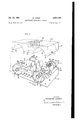
- FIG 2 is an expanded view of my novel radio cabinet ShOWiIlg the block-like parts thereof separated, and the means for supporting the various operating elements.
- Figure 3 is a cross-sectional view taken from line 3-3 of Figure 2 l00king in the direction of the arrows.
- Figure 4 is a cross-sectional view taken from line 4--4 of Figure 1 looking in the direction of the arrows.
- Figure "5 is an elevation of my novel loop antenna.
- Figure 6 is a cross-sectional view taken from line GB of Figure 5 looking in the direction of the arrows.
- Figure 7 is a view in perspective of the chassis pan of my novel cabinet.
- my novel radio cabinet comprises a chassis pan or base section ii) and a translucent or transparent plastic top section 'I I.
- the chassis i0 is preferably metallic although it may be made of any suitable material and may have any desired ornamental surfacing or veneer including plastic sheeting which may match the top section.
- the chassis I0 has a front wall l2, side walls 13 and M, a back wall i5 and a top wall l1.
- Top wall ll of chassis I0 is provided with openings 2
- the top wall I! is cut out at 25 on the right side to provide a recess for the tuning condenser, andis cut out at 32a. on the left side to provide a reces for the speaker.
- the flange 33 of speaker 32 is bolted to the portion of top wall I! surrounding opening 32a.
- a deflecting baflle plate 3! is mounted over the speaker 32, being sloped to direct the sound from the loud speaker towards the front.
- Another object of my invention is the mounting of the volume control knob in the speaker opening of my cabinet.
- Another object of my invention is the provision of novel loop antenna mounting mean in connection with my novel cabinet.
- is secured to the back
- the front of wall 12 of chassis ill in front of the speaker -32 is provided with a metallic ring 39 securedin any-suitable manner to the said wall I2," half of the ring 39 projecting above the top of wall l2.
- the metallic ring 39 is preferably finished outside and inside with a mirror finish having either a silver or gold appearance, but which, of course, may be of any appropriate wall I axially alignedwith the front ring 39 and finished in the same manner as the front ring 39.
- a perforated plate 43 is secured in any suitable manner in the front ring 39 and a similar perforated metal plate 44 is secured in the back ring 4
- the front plate 43 carries on the back thereof a volume control 45 of a standard type, the said volume control being appropriately connected to the chassis.
- the volume control knob 48 operates in an appropriate bearing in the plate 43 and is accessible from the front of the cabinet. The mounting of the volume control knob in the center of the grill establishes a direct functional connection in the mind of the user between the source of sound and its control.
- the clear plastic top block is provided with a semi-cylindrical recess 50 registering with the rings 39 and 4
- Thecenter-of the block is provided with a series of vertical cyl'ndrical openings 53 which pass over and receive the tubes 23.
- the surfaces 54 and 55 register with and rest on respectively the ledges
- Any suitable securement'means may be used in order to hold the block II on block I9.
- bolts '60 may be insertedfrom the underside of ledges
- Suitable friction securing members or latch members may also be used to inter-secure the blocks II and base If).
- scribed may extend from the chassis up through Also, the tubes I00 hereinafter deholes 53 and be threaded at the top to receive threaded perforated covers I02.
- the condenser 26 is secured in recess 25, being-mounted in an appropriate frame 10 for this purpose.
- gang condenser 26 is provided with the operating shaft 1
- carries at its forward end the pulley disk 13.
- the pulley'disk 13 is connected by the rigid link 74 to the tubular sleeve 15 which rotates freely on the rotatable shaft 16.
- the sleeve 15 rotates exactly in accordance therewith and carries around the pointer 11 mounted thereon to indicate the .position of the movable plates of the condenser stack.
- the shaft 16 is journalled in an appropriate bearing 80 in the support bracket 8
- the inner end of shaft 16 carries the small pulley 86.
- the cable 81 crosses beneath the pulley 86.
- One side of the cable is led beneath the diagonally arranged guide pulley 88 to one side of pulley 73 and the other side of the cable is led beneath the diagonaily arranged pulley to the other side of the main pulley 13.
- the diagonally arranged guide pulleys 88 and 90 thus carry the cable 81 so that the portions thereof which engage pulley 86 extend in the plane of pulley 86 and the portions thereof which engage pulley I3 extend in the plane of pulley 73; the cable thus has no tendency whatever to slip off the pulleys 86 and 13.
- Pulleys 88 and 89 are supported respectively on shafts 9
- the front wall I 2 of the base l3 carries the ring 94, half of which protrudes above the top of the said wall as seen in Figure 3.
- the back wall l5 supports the ring in the samemanner. Rings 94 and 95 are finished to have the same appearance as rings 39 and 4
- the lower half of-the ring'94 is filled with a half-circular plastic disk 91 which extends in front of the front wall of the chassis Ill.
- the upper half of the rings is filled with a half circle 98 of transparent Lucite or other transparent material, suitably marked or scored on the back to provide tuning indicia for registry with the needle.
- the ring 95 at the rear is also filled with a circle 99 of perforated metallic material similar to the filler for disk 4
- are finished with a mirror finish corresponding exactly to the finish of rings 39 and 4
- cooperating withrings 94 and 95 appear to form a single continuous mirror finished cylinder visible on the right side through a Lucite of the top I
- the vertical openings 53 in the top block H are provided with a mirror finish I09, at least part way -up, which is visible through the block as a series of apparently metallic tubes partly surrounding the radio tubes 23.
- the mirror finish I39 reflects heat from-the tubes.
- actual cylinders I 00 may be used secured to the panel l7. These cylinders I09 may be used for securement purposes as above described.
- a metallic grill or a screen I04 of any other suitable material may be secured in any suitable manner in the ring I02 to close ofi the top of opening 53 while nevertheless permitting the passage of air therethrough.
- Ventilation of the cabinet and of the tubes and removal of heat from the cabinet is then facilitated by the up draft from the small openings 22 into the vertical openings 53 around th radio tubes 23; then out through the top of vertical openings 53 through the grill I04.
- a push switch IIO may be pro.- vided to switch from loud speaker to earphones; a push switch II I to switch from treble to base; a switch I 52 to switch from radio to phonograph;
- the wire I2? passes through the insulating sleeve I which is received in the hollow longitudinal opening ISI of the central stud I25.
- the stud I25 is threaded at I 33 to be screwed into the tapped openings I54 of the small supporting metallic housing I35.
- the stud I25 is provided with the annular flange I3! which thus secures the loop antenna I20-I2I-I22 between the flange I31 and the end of housing I35.
- housing I35 is secured to the vertical metallic tube I50.
- the lead I28 passes down the metallic tube M0 being insulated there.- from in any suitable manner and terminates in the metallic kncb I iI which in turn is insulated by insulating washer I42 from the metallic tube I40.
- the metallic tube I is provided with the annular flange I45.
- the flange 545 resting on the top of the cabinet determines its position therein as shown in Figure 3.
- the tube I40 passes through the opening I adjustably supported below opening I50 on the bracket I55. also carried by bracket I55 but insulated therefrom.
- a suitable electrical connection may be made to the tube I40 and another connection may be mad to the contact I58 which engages the tip MI of lead I28. Connections may thus be made to the antenna I20 for ground and for the radio circuit. This connection for the antenna runs from contact I58 and knob I4I up through lead I28 to the bent wire I21, then to the outside of the loop I20 around the loop I20 to the inside of the loop,
- a spring contact member I58 is v then through the wire I24 through the metallic stud I25, through housing I35 and back to tube I40. The usual connections are then made from tube I40 and contact I58 to the remainder of the circuit.
- bent wire I21, wire I24, tube I40, stud I25 and its flange I31, as well as housing I35, may all be treated to have a finish similar to that of rings 39 and 94; except that the lower end of tube I40 which engages the sleeve I55 may be treated where necessary to have a good conducting surface.
- loop antenna I20 may readily be rotated in its mounting while nevertheless it is always in engagement with sleeve I55 and spring contact I58.
- the particular novel method for operating the tuning condenser herein shown simpiifies the appearance of the cabinet and provides a novel Vernier adjustment for a needle or tuning pointer which is concentric with the tuning knob.
- a radio cabinet including a chassis section and a top section,.said top section comprising a block of light transmitting material; radio elements mounted on said chassis; and recesses in said block receiving said radio elements.
- a radio cabinet including a chassis section and a top section; said top section comprising a block of light transmitting material; radio elements mounted on said chassisj a loud speaker mounted on said chassis; recesses in said block receiving said radio elements; and an additional recess in said block forming a sound chamber for said loud speaker.
- a radio cabinet including a chassissection and a top section; said top section comprising a block of light transmitting material; radio elements including radio tubes mounted on said chassis; recesses in said block receiving said radio elements and said radio tubes.
- a radio cabinet including a chassis section and a top section; said top section comprising a block of light transmitting material; radio elements including radio tubes mounted on said chassis; recesses in said block receiving said radio wanes, 1.4a
- a radio cabinet including av chassis section ments including radio tubes mounted-on said chassis; recesses in-said block receiving said radio *elements and said radio tubes; said'recesses com- .prising an individual recess for each-tube; each of said individual tube recesses being open at .10.on top of said cabinet. .the' top.
- A' radio cabinet including. a chassissection and a top section, said top section comprising a .block of light transmitting material; radio elements mounted on said chassis;-.and recesses in .said block receiving said-radio elements; certain 20f said: recesses having an opaque lining.
- a radio cabinet including a chassis section and atopsectiomsaid top section comprising a block of light transmitting material; radio elegments mounted on saidzchassis; and recessesin said block receiving said radio elements; certain of said recessesl having an opaque lining; said lined recesses appearing. to be solid structures within said block.
- a radio cabinet including. a chassis section and a top section, said top section comprising a block of light transmitting material; radio .ele-- ments. mounted on said chassis; and recesses. in said blccl; receiving said .radio elements; certain .of said recesses having a light reflecting lining.
- a radio cabinet includinga chassis section recesses in .said block" receiving said Notices comprising an individual-recess for each tube; each of said-individualtube recesses being open at the. top; openings .in :said chassisadiacent each tube; said openings. in said chassis .and said. open top tube recesses, providing.
- a radio cabinet including a chassissection .and. a. top section, .said..top section. comprising "a block of light transmitting material; radio. elelments mounted on:said chassis; recessesinsaid block receiving. said .radio elements; and a: loop "antennacomprising a p supported within a .light'transmitting disk; said loop being mounted .13. vA radio cabinet.
- chassis section and a top section,-said"top section comprising a block of light transmittingmaterial; radio elements mounted on said chassis; recesses in said block receiving said radio elements; a lcopantenna comprising aloop supported within a light transmitting disk; said loop being mounted on top of said cabinet; and a support-for saidloop antenna; an opening in said block for rotatably receiving said support.
- a radio cabinet including a chassis section and a top section; said top section comprising a block of light transmitting material;--radio elements mountedon said chassis; a loudspeaker mounted on said-chassis; recesses in said block receiving said radio elements; an additional recess in said block forming a sound chamber for a said loudspeaker;- an airpermeable. closure -for one end of said sound chamber; and avolume control member mounted on said air permeable closure.
Description
Jan. 23, 1951 R. LOEWY 2,539,146
TRANSPARENT BLOCK RADIO CABINET Filed March 19, 1947 5 Sheets-Sheet 1 FIG. I
IN VEN TOR.
RAYMOND LOEWY BY TJM/ ATTORN EYS Jan. 23, 1951 R. LOEWY 2,539,146
TRANSPARENT BLOCK RADIO CABINET Filed March 19, 1947 '5 Sheets-Sheet 2 INVENTOR. RAYMOND LOEWY 9W jaw/ ATTORN EYS Jan. 23, 1951 Filed March 19 R. LOEWY TRANSPARENT BLOCK RADIO CABINET 5 Sheets-Sheet 3 INVENTO RAYMOND LO Y BY ATTORNEYS Jan. 23, 1951 R. LOEWY 2,539,146
TRANSPARENT BLOCK RADIO CABINET Filed March 19, 1947 5 Sheets-Sheet 4 INVENTOR. RAYMOND LOEWY FIG.5
ATTORNEYS Jan. 23, 1951 LQEWY 2,539,146
TRANSPARENT BLOCK RADIO CABINET Filed March 19, 1947 5 sheets-sheet 5 FIG. 7
IN V EN TOR.
RAYMOND LOEWY BY ATTORNEYS Patented Jan. 23, 1951 i: 'i'i UNITED STATES PATENT OFFICE TRANSPARENT BLOCK RADIO CABINET Raymond Loewy, Sands Point, N. Y.
Application March 19, 1947, Serial No. 735,593
lVfy present invention relates to radios and more--. particularly to novel and simply manufactured housings therefor, as well as to simplified operating means for the tuning condenser,
novel baiile construction for the loud speaker,
and novel mounting for a loop antenna, all combined and integrated with the novel housing for the radio.
My invention specifically contemplates the formation of a radio cabinet in such manner that it comprises essentially a block of clear insulating material, the said block being provided with openings and recesses to receive and position the various parts of the radio.
Thus the primary object of my invention is the'provision of a novel cabinet or enclosure for a radio set consisting of blocks bored and recessed to contain and position the various radio parts and so arranged that all parts of the radio may be rendered accessible simply by lifting off a part of the cabinet.
Another object of my invention is the arrangement of a novel radio cabinet so that itconsists of blocks of translucent or transparent material,
bored, and recessed to support and position the radio parts.
7 Another object of my invention is the formation of a novel radio cabinet of transparent material so arranged that functional parts of the radio itself become visible to form part of the final design.
Another object of my invention is the provision of a novel loud speaker baflie arrangement which includes recesses in the blocks forming the cabinet for supporting and positionin the loud :speaker as well as additional bafiie means where they may be required.
' Still another object of my invention is the provision of novel tuning means in connection with my novel radio cabinet and the arrangement of a novel method of cooperation between the tuning means and the cabinet to provide readily visible indicia showing the position of the tuning means.
Another object of my invention is the provision of novel ventilating means for my radio cabinet.
Another object of my invention is the provision of novel means for mounting a loud speaker A including the utilization of the chassis itself as part of the baflle structure.
14 Claims. (01. 250- 14) Another object of my invention is the arrangement and construction of a novel loop antenna.
The foregoin and many other objects of my invention will become apparent in the following description and drawings in which:
Figure 1 is a view in perspective of my novel radio cabinet. I s
Figure 2 is an expanded view of my novel radio cabinet ShOWiIlg the block-like parts thereof separated, and the means for supporting the various operating elements.
Figure 3 is a cross-sectional view taken from line 3-3 of Figure 2 l00king in the direction of the arrows.
Figure 4 is a cross-sectional view taken from line 4--4 of Figure 1 looking in the direction of the arrows.
Figure "5 is an elevation of my novel loop antenna.
Figure 6 is a cross-sectional view taken from line GB of Figure 5 looking in the direction of the arrows.
Figure 7 is a view in perspective of the chassis pan of my novel cabinet.
Referring now to Figure 1, 2 and '7, my novel radio cabinet comprises a chassis pan or base section ii) and a translucent or transparent plastic top section 'I I.
v V The chassis i0 is preferably metallic although it may be made of any suitable material and may have any desired ornamental surfacing or veneer including plastic sheeting which may match the top section. The chassis I0 has a front wall l2, side walls 13 and M, a back wall i5 and a top wall l1.
Top wall ll of chassis I0 is provided with openings 2| receiving the sockets for the tubes 23. Small openings '22 surround each of the tube lsocket openings 2| for ventilation purposes as hereinafter described. The top wall I! is cut out at 25 on the right side to provide a recess for the tuning condenser, andis cut out at 32a. on the left side to provide a reces for the speaker. The flange 33 of speaker 32 is bolted to the portion of top wall I! surrounding opening 32a.
A deflecting baflle plate 3! is mounted over the speaker 32, being sloped to direct the sound from the loud speaker towards the front.
Another object of my invention is the mounting of the volume control knob in the speaker opening of my cabinet.
Another object of my invention is the provision of novel loop antenna mounting mean in connection with my novel cabinet.
color. A similar ring 4| is secured to the back The front of wall 12 of chassis ill in front of the speaker -32 is provided with a metallic ring 39 securedin any-suitable manner to the said wall I2," half of the ring 39 projecting above the top of wall l2. The metallic ring 39 is preferably finished outside and inside with a mirror finish having either a silver or gold appearance, but which, of course, may be of any appropriate wall I axially alignedwith the front ring 39 and finished in the same manner as the front ring 39. A perforated plate 43 is secured in any suitable manner in the front ring 39 and a similar perforated metal plate 44 is secured in the back ring 4|. The perforations in the front plate 43 provide an exit for the sound from the loud speaker 32.
The front plate 43 carries on the back thereof a volume control 45 of a standard type, the said volume control being appropriately connected to the chassis. The volume control knob 48 operates in an appropriate bearing in the plate 43 and is accessible from the front of the cabinet. The mounting of the volume control knob in the center of the grill establishes a direct functional connection in the mind of the user between the source of sound and its control.
The clear plastic top block is provided with a semi-cylindrical recess 50 registering with the rings 39 and 4|. It is also provided with the semi-cylindrical recess 5|, registering with the right hand side members-of the base as hereinafter described. Thecenter-of the block is provided with a series of vertical cyl'ndrical openings 53 which pass over and receive the tubes 23.
When the block II is mounted in place on the chassis H], the surfaces 54 and 55 register with and rest on respectively the ledges |3aand |4a of walls l3 and I4, and the surface '51rests on the top panel I. Any suitable securement'means may be used in order to hold the block II on block I9. Thus, for instance, where desired, bolts '60 may be insertedfrom the underside of ledges |3a and Ida on each side to enter 'into tapped openings 6| in sections 54 and 55 of the block 11.
Suitable friction securing members or latch members may also be used to inter-secure the blocks II and base If). The topsofwall I! may also have upwardly projecting studs which may be a tight frictionalfit in appropriate openings in block II, or which may 'pass entirely through openings in book to=be held by a nut or knob of clear plastic or-other suitable material turned into a counter bore at the upper end of the openings in block Or appropriately cross-sectioned registering key-ways may be formed in meeting edges of blocks -|0 and H, andsliding keys may be introduced to hold blocks I0 and 'II together. scribed may extend from the chassis up through Also, the tubes I00 hereinafter deholes 53 and be threaded at the top to receive threaded perforated covers I02.
As is shown in Figures '2, 3 and 7, the condenser 26 is secured in recess 25, being-mounted in an appropriate frame 10 for this purpose. The
The shaft 16 is journalled in an appropriate bearing 80 in the support bracket 8| mounted on the chassis and is a so supported in the'opening 82 of the sleeve 15 for rotation -by tuning knob 84. The inner end of shaft 16 carries the small pulley 86.
As shown in Figures 2 and 3, the cable 81 crosses beneath the pulley 86. One side of the cable is led beneath the diagonally arranged guide pulley 88 to one side of pulley 73 and the other side of the cable is led beneath the diagonaily arranged pulley to the other side of the main pulley 13. The diagonally arranged guide pulleys 88 and 90 thus carry the cable 81 so that the portions thereof which engage pulley 86 extend in the plane of pulley 86 and the portions thereof which engage pulley I3 extend in the plane of pulley 73; the cable thus has no tendency whatever to slip off the pulleys 86 and 13.
A pilot light -93 secured to the chassis and located just behind the front wall of chassis |0 causing light to impinge-on the lower surface of the half circle of Lucite 98 causin the light to be visible at the scored indicia.
The ring 95 at the rear is also filled with a circle 99 of perforated metallic material similar to the filler for disk 4| The inner surfaces 0f the recesses 50 and 5| are finished with a mirror finish corresponding exactly to the finish of rings 39 and 4| and rings 94 and 95 so that when the block is in position on base It], the rings 39 and 4| together with the inner mirror finish of recess 5!! seem to form a single inner mirror finished cylinder visible through the Lucite of the top H. Similarly, the mirror finish of recess 5| cooperating withrings 94 and 95 appear to form a single continuous mirror finished cylinder visible on the right side through a Lucite of the top I The vertical openings 53 in the top block H are provided with a mirror finish I09, at least part way -up, which is visible through the block as a series of apparently metallic tubes partly surrounding the radio tubes 23. The mirror finish I39 reflects heat from-the tubes. I
Where desired, actual cylinders I 00 may be used secured to the panel l7. These cylinders I09 may be used for securement purposes as above described.
Also a metallic grill or a screen I04 of any other suitable material may be secured in any suitable manner in the ring I02 to close ofi the top of opening 53 while nevertheless permitting the passage of air therethrough.
Ventilation of the cabinet and of the tubes and removal of heat from the cabinet is then facilitated by the up draft from the small openings 22 into the vertical openings 53 around th radio tubes 23; then out through the top of vertical openings 53 through the grill I04.
Where desired, other controls may, of course, be added. Thus, a push switch IIO may be pro.- vided to switch from loud speaker to earphones; a push switch II I to switch from treble to base; a switch I 52 to switch from radio to phonograph;
and the on-ofi switch I13 may also be provided cabinet is shown specifically in Figures 5 and 6.
It consists of a loop l which is sandwiched between two disks I2I and I22 of Lucite which are pressed together and molded around the loop I20 to form an integral unit. The inner end of the loop is connected by the vertical metal wire I24 to the central metallic supporting stud I25 of the loop. The outer end of the loop is connected by the bent metal wire IE! to the lead I28. The wire I2? passes through the insulating sleeve I which is received in the hollow longitudinal opening ISI of the central stud I25. The stud I25 is threaded at I 33 to be screwed into the tapped openings I54 of the small supporting metallic housing I35. The stud I25 is provided with the annular flange I3! which thus secures the loop antenna I20-I2I-I22 between the flange I31 and the end of housing I35.
The bottom of housing I35 is secured to the vertical metallic tube I50. The lead I28 passes down the metallic tube M0 being insulated there.- from in any suitable manner and terminates in the metallic kncb I iI which in turn is insulated by insulating washer I42 from the metallic tube I40.
The metallic tube I is provided with the annular flange I45. When the metallic tube I40 is inserted in the vertical openin I in th top of housing block H, the flange 545 resting on the top of the cabinet determines its position therein as shown in Figure 3.
The tube I40 passes through the opening I adjustably supported below opening I50 on the bracket I55. also carried by bracket I55 but insulated therefrom.
When, therefore, the tube I50 is inserted through the openings Hi0 and I55, a suitable electrical connection may be made to the tube I40 and another connection may be mad to the contact I58 which engages the tip MI of lead I28. Connections may thus be made to the antenna I20 for ground and for the radio circuit. This connection for the antenna runs from contact I58 and knob I4I up through lead I28 to the bent wire I21, then to the outside of the loop I20 around the loop I20 to the inside of the loop,
A spring contact member I58 is v then through the wire I24 through the metallic stud I25, through housing I35 and back to tube I40. The usual connections are then made from tube I40 and contact I58 to the remainder of the circuit.
The bent wire I21, wire I24, tube I40, stud I25 and its flange I31, as well as housing I35, may all be treated to have a finish similar to that of rings 39 and 94; except that the lower end of tube I40 which engages the sleeve I55 may be treated where necessary to have a good conducting surface.
It will thus be clear that the loop antenna I20 may readily be rotated in its mounting while nevertheless it is always in engagement with sleeve I55 and spring contact I58.
By means of the foregoing, I have provided a novel housing construction which by itsmechanical conformation provides a novel and ornamental appearance for the radio set. The loop antenna mounting is so arranged that, instead of detracting from the appearance of the radio sets as has previously been the case where loop antennae were used outside the housing, it enhances the appearance of the radio set by utilizing smooth lines conforming 'to the lines of the mechanical and ornamental parts of the cabinet itself and by utilizing materials matching the parts of the cabinet.
The mechanical constructions herein described aid, not merely, in the operation of the set, but provide a novel simplified mounting for the loud speaker, the radio tubes and the tuning condenser, and also cooperate with the main portion of the cabinet to enhance the novel ornamental appearance.
The particular novel method for operating the tuning condenser herein shown simpiifies the appearance of the cabinet and provides a novel Vernier adjustment for a needle or tuning pointer which is concentric with the tuning knob.
In the foregoing, I have described my invention solely in connection with preferred illustrative embodiments thereof. Since many variations and modifications of my invention will now be obvious to those skilled in the art, I prefer to be bound not by the specific disclosures herein, but only by the appended claims.
I claim:
1. A radio cabinet including a chassis section and a top section,.said top section comprising a block of light transmitting material; radio elements mounted on said chassis; and recesses in said block receiving said radio elements.
2. A radio cabinet including a chassis section and a top section; said top section comprising a block of light transmitting material; radio elements mounted on said chassisj a loud speaker mounted on said chassis; recesses in said block receiving said radio elements; and an additional recess in said block forming a sound chamber for said loud speaker.
3. A radio cabinet including a chassissection and a top section; said top section comprising a block of light transmitting material; radio elements including radio tubes mounted on said chassis; recesses in said block receiving said radio elements and said radio tubes.
4. A radio cabinet including a chassis section and a top section; said top section comprising a block of light transmitting material; radio elements including radio tubes mounted on said chassis; recesses in said block receiving said radio wanes, 1.4a
. elements and'said radio tubes; said recesses-comprising: an individual recess for each tube.
55. A radio cabinet including av chassis section ments including radio tubes mounted-on said chassis; recesses in-said block receiving said radio *elements and said radio tubes; said'recesses com- .prising an individual recess for each-tube; each of said individual tube recesses being open at .10.on top of said cabinet. .the' top.
6..A radio cabinet includinga chassis section and a top section; said top section comprising a "block oilight: transmitting material; radio elewmentsincluding radio tubes mounted oinsaidh chassis; recesses in: said block receiving saidradio elements and said radio tubes; said:recesses comprising an individual recess for each tubepeach :of said-individual tube recesses being open=at the top;:openings in said chassis adjacent eachtube;
said openings in said chassis and saidcpen top tube recesses providinga ventilating passageivior :each tube.
7.;A' radio cabinet including. a chassissection and a top section, said top section comprising a .block of light transmitting material; radio elements mounted on said chassis;-.and recesses in .said block receiving said-radio elements; certain 20f said: recesses having an opaque lining.
8. A radio cabinet including a chassis section and atopsectiomsaid top section comprising a block of light transmitting material; radio elegments mounted on saidzchassis; and recessesin said block receiving said radio elements; certain of said recessesl having an opaque lining; said lined recesses appearing. to be solid structures within said block.
9. A radio cabinet including. a chassis section and a top section, said top section comprising a block of light transmitting material; radio .ele-- ments. mounted on said chassis; and recesses. in said blccl; receiving said .radio elements; certain .of said recesses having a light reflecting lining.
10. A radio cabinet including achassis section and atop section; said. top .sectioncomprising a .block of light transmitting material; :radio ele- "ments including radio tubes =mountedron said chassis; recesses insaid block receivingxsaid radio elements and said radio tubes; said recesses comprising an individual recess for each tube; .each
:oftsaidindividual tube recesses being open at the top; openingsin'said chassis adjacent ieachtube; said openings in said chassis and said :open top .tuberecesses providing. a ventilating passageior each tube; and ornamental air permeable covers fornthe tops of said tube recesses.
11. A radio cabinet includinga chassis section recesses in .said block" receiving said cesses comprising an individual-recess for each tube; each of said-individualtube recesses being open at the. top; openings .in :said chassisadiacent each tube; said openings. in said chassis .and said. open top tube recesses, providing. a
ventilating passage foreach tube; ornamental air permeable covers for the tops of said. tube re- 8 ;.cesses;.and ornamentalfront members carried by said chassis matching said ornamental covers.
1 12. A radio cabinet including a chassissection .and. a. top section, .said..top section. comprising "a block of light transmitting material; radio. elelments mounted on:said chassis; recessesinsaid block receiving. said .radio elements; and a: loop "antennacomprising a p supported within a .light'transmitting disk; said loop being mounted .13. vA radio cabinet. including a chassis section and a top section,-said"top section comprising a block of light transmittingmaterial; radio elements mounted on said chassis; recesses in said block receiving said radio elements; a lcopantenna comprising aloop supported within a light transmitting disk; said loop being mounted on top of said cabinet; and a support-for saidloop antenna; an opening in said block for rotatably receiving said support.
14. A radio cabinet including a chassis section and a top section; said top section comprising a block of light transmitting material;--radio elements mountedon said chassis; a loudspeaker mounted on said-chassis; recesses in said block receiving said radio elements; an additional recess in said block forming a sound chamber for a said loudspeaker;- an airpermeable. closure -for one end of said sound chamber; and avolume control member mounted on said air permeable closure.
RAYMOND LOEWY.
REFERENCES CITED The following references are of record in the file of this patent:
UNITED STATES PATENTS Number Name Date D. 150,277 Wedemeyer July 13, 1948 1524.195 Rayder Jan; 27, 1925 1,601,968 Huth Oct. 5, 1926 1,634,676 Meyer July 5, 1927 1,666,480 Zillger Apr. 17, 1928 1,713,194 Ross May 14, 1929 1,716,538 "Blackmore June 11, 1929 1,778,693 Semple Oct. 14, 1930 1,816,718 Bond July 28, 1931 1,887,185 Quinby Nov. 8, 1932 1,983,322 Steward Dec. 4, 1934 1,995,171 DeTar Mar. 19, 1935 2,070,088 Montaruli Feb. 9, 1937 2,072 240 Zigler Mar. 2,, 1937 2,088,454 Whisk July 27, 1937 2,141,423 Tolerton Dec. 27,. 1938 2,143,532 Andrews Jan. 10, 1939 2,144,325 Buchardt Jan. 17, 1 939 2,187,011 Braden Jan. 16, 1940 2,250,337 McDonald July 22, 1941 2,439,412 Mitchell Apr. 13, 1948 FOREIGN PATENTS Number Country Date 834,981 France Dec. 1938 558,265 Great Britain Dec. 29, 1943 OTHER REFERENCES "Radio'Retailing, Sept. 1925; article on upper part'of page 426.
Priority Applications (1)
| Application Number | Priority Date | Filing Date | Title |
|---|---|---|---|
| US735593A US2539146A (en) | 1947-03-19 | 1947-03-19 | Transparent block radio cabinet |
Applications Claiming Priority (1)
| Application Number | Priority Date | Filing Date | Title |
|---|---|---|---|
| US735593A US2539146A (en) | 1947-03-19 | 1947-03-19 | Transparent block radio cabinet |
Publications (1)
| Publication Number | Publication Date |
|---|---|
| US2539146A true US2539146A (en) | 1951-01-23 |
Family
ID=24956429
Family Applications (1)
| Application Number | Title | Priority Date | Filing Date |
|---|---|---|---|
| US735593A Expired - Lifetime US2539146A (en) | 1947-03-19 | 1947-03-19 | Transparent block radio cabinet |
Country Status (1)
| Country | Link |
|---|---|
| US (1) | US2539146A (en) |
Cited By (3)
| Publication number | Priority date | Publication date | Assignee | Title |
|---|---|---|---|---|
| US2737579A (en) * | 1951-04-06 | 1956-03-06 | Acf Ind Inc | Amplifier assembly |
| US2824477A (en) * | 1953-05-14 | 1958-02-25 | Tolbert F Cheek | Power pneumatic |
| US20050254678A1 (en) * | 2004-05-14 | 2005-11-17 | Wearing John A | Portable audio system with changeable functionality |
Citations (22)
| Publication number | Priority date | Publication date | Assignee | Title |
|---|---|---|---|---|
| GB558265A (en) * | ||||
| US1524105A (en) * | 1924-03-07 | 1925-01-27 | Joseph A Rayder | Radiocabinet |
| US1601968A (en) * | 1924-06-11 | 1926-10-05 | Walter H Huth | Adjusting handle |
| US1634676A (en) * | 1922-12-01 | 1927-07-05 | James R English | Vernier device |
| US1666480A (en) * | 1924-12-09 | 1928-04-17 | Music Master Corp | Means for adjusting the antenna of radio apparatus |
| US1713194A (en) * | 1924-12-27 | 1929-05-14 | Gen Electric | Vernier drive |
| US1716538A (en) * | 1924-12-31 | 1929-06-11 | Charles C Blackmore | Radio apparatus |
| US1778693A (en) * | 1928-02-24 | 1930-10-14 | Claravox Inc | Loud-speaker |
| US1816718A (en) * | 1930-02-19 | 1931-07-28 | Gen Electric | Shielded radio receiving apparatus and the like |
| US1887185A (en) * | 1929-02-20 | 1932-11-08 | Rca Corp | Sound reproducer |
| US1983322A (en) * | 1933-01-13 | 1934-12-04 | Henry P Stewart | Transportation package |
| US1995171A (en) * | 1933-04-29 | 1935-03-19 | Rca Corp | Manual radio control means |
| US2070088A (en) * | 1934-05-17 | 1937-02-09 | Montaruli Antonio | Radio cabinet |
| US2072240A (en) * | 1932-07-13 | 1937-03-02 | Rca Corp | Radio circuit actuating device |
| US2088454A (en) * | 1935-08-02 | 1937-07-27 | Sign Animation Corp | Radiation elimination |
| FR834981A (en) * | 1937-03-13 | 1938-12-08 | Aeg | Electric wave filter |
| US2141423A (en) * | 1936-03-28 | 1938-12-27 | Magnavox Company Inc | Loudspeaker mounting |
| US2143532A (en) * | 1933-04-08 | 1939-01-10 | Edward F Andrews | Radio receiver |
| US2144325A (en) * | 1935-02-11 | 1939-01-17 | Telefunken Gmbh | Tuning dial arrangement |
| US2187011A (en) * | 1937-03-13 | 1940-01-16 | Paul F Braden | Cooling means for an electrical apparatus |
| US2250387A (en) * | 1939-10-06 | 1941-07-22 | Jr Eugene F Mcdonald | Radio apparatus |
| US2439412A (en) * | 1944-08-04 | 1948-04-13 | Motorola Inc | Multistage plug-in frequency-determining unit |
-
1947
- 1947-03-19 US US735593A patent/US2539146A/en not_active Expired - Lifetime
Patent Citations (22)
| Publication number | Priority date | Publication date | Assignee | Title |
|---|---|---|---|---|
| GB558265A (en) * | ||||
| US1634676A (en) * | 1922-12-01 | 1927-07-05 | James R English | Vernier device |
| US1524105A (en) * | 1924-03-07 | 1925-01-27 | Joseph A Rayder | Radiocabinet |
| US1601968A (en) * | 1924-06-11 | 1926-10-05 | Walter H Huth | Adjusting handle |
| US1666480A (en) * | 1924-12-09 | 1928-04-17 | Music Master Corp | Means for adjusting the antenna of radio apparatus |
| US1713194A (en) * | 1924-12-27 | 1929-05-14 | Gen Electric | Vernier drive |
| US1716538A (en) * | 1924-12-31 | 1929-06-11 | Charles C Blackmore | Radio apparatus |
| US1778693A (en) * | 1928-02-24 | 1930-10-14 | Claravox Inc | Loud-speaker |
| US1887185A (en) * | 1929-02-20 | 1932-11-08 | Rca Corp | Sound reproducer |
| US1816718A (en) * | 1930-02-19 | 1931-07-28 | Gen Electric | Shielded radio receiving apparatus and the like |
| US2072240A (en) * | 1932-07-13 | 1937-03-02 | Rca Corp | Radio circuit actuating device |
| US1983322A (en) * | 1933-01-13 | 1934-12-04 | Henry P Stewart | Transportation package |
| US2143532A (en) * | 1933-04-08 | 1939-01-10 | Edward F Andrews | Radio receiver |
| US1995171A (en) * | 1933-04-29 | 1935-03-19 | Rca Corp | Manual radio control means |
| US2070088A (en) * | 1934-05-17 | 1937-02-09 | Montaruli Antonio | Radio cabinet |
| US2144325A (en) * | 1935-02-11 | 1939-01-17 | Telefunken Gmbh | Tuning dial arrangement |
| US2088454A (en) * | 1935-08-02 | 1937-07-27 | Sign Animation Corp | Radiation elimination |
| US2141423A (en) * | 1936-03-28 | 1938-12-27 | Magnavox Company Inc | Loudspeaker mounting |
| FR834981A (en) * | 1937-03-13 | 1938-12-08 | Aeg | Electric wave filter |
| US2187011A (en) * | 1937-03-13 | 1940-01-16 | Paul F Braden | Cooling means for an electrical apparatus |
| US2250387A (en) * | 1939-10-06 | 1941-07-22 | Jr Eugene F Mcdonald | Radio apparatus |
| US2439412A (en) * | 1944-08-04 | 1948-04-13 | Motorola Inc | Multistage plug-in frequency-determining unit |
Cited By (4)
| Publication number | Priority date | Publication date | Assignee | Title |
|---|---|---|---|---|
| US2737579A (en) * | 1951-04-06 | 1956-03-06 | Acf Ind Inc | Amplifier assembly |
| US2824477A (en) * | 1953-05-14 | 1958-02-25 | Tolbert F Cheek | Power pneumatic |
| US20050254678A1 (en) * | 2004-05-14 | 2005-11-17 | Wearing John A | Portable audio system with changeable functionality |
| US8027499B2 (en) | 2004-05-14 | 2011-09-27 | Wearing John A | Portable audio system with changeable functionality |
Similar Documents
| Publication | Publication Date | Title |
|---|---|---|
| US2539146A (en) | Transparent block radio cabinet | |
| US4146919A (en) | Rotating hanging lamp | |
| US2070088A (en) | Radio cabinet | |
| US2272660A (en) | Tuning indicator | |
| US2885992A (en) | Dial indicator | |
| US1898642A (en) | Means for indicating tones by color | |
| US2062632A (en) | Radio receiving set | |
| US2507707A (en) | Lamp radio | |
| US2212315A (en) | Radioelectric control device | |
| US2189455A (en) | Radio set | |
| USD245564S (en) | Cover for a plate | |
| US2275506A (en) | Combined article of furniture and radio receiving set | |
| US2291796A (en) | Combined article of furniture and radio receiving set | |
| GB499108A (en) | Improvements in or relating to apparatus, such as radio receivers, for converting acoustically-modulated oscillations into sound oscillations | |
| US3329122A (en) | Gramophone cabinet for radio receiving sets | |
| US2511963A (en) | Brener | |
| US2131797A (en) | Transmission means for control members | |
| USD197668S (en) | Indicator dial for a radio or the like | |
| USD248445S (en) | Knob | |
| US2106152A (en) | Indicating and control apparatus | |
| US2003405A (en) | Combination clock and radio | |
| US2068110A (en) | Tuning dial | |
| US1842420A (en) | Method of and apparatus for reproducing sound waves and light waves | |
| US2591667A (en) | Illuminated tuning dial | |
| US1868433A (en) | Radiodial or station selector |