US2531908A - Radio navigational aid - Google Patents
Radio navigational aid Download PDFInfo
- Publication number
- US2531908A US2531908A US764155A US76415547A US2531908A US 2531908 A US2531908 A US 2531908A US 764155 A US764155 A US 764155A US 76415547 A US76415547 A US 76415547A US 2531908 A US2531908 A US 2531908A
- Authority
- US
- United States
- Prior art keywords
- phase
- signals
- frequency
- lane
- pattern
- Prior art date
- Legal status (The legal status is an assumption and is not a legal conclusion. Google has not performed a legal analysis and makes no representation as to the accuracy of the status listed.)
- Expired - Lifetime
Links
Images


Classifications
-
- G—PHYSICS
- G01—MEASURING; TESTING
- G01S—RADIO DIRECTION-FINDING; RADIO NAVIGATION; DETERMINING DISTANCE OR VELOCITY BY USE OF RADIO WAVES; LOCATING OR PRESENCE-DETECTING BY USE OF THE REFLECTION OR RERADIATION OF RADIO WAVES; ANALOGOUS ARRANGEMENTS USING OTHER WAVES
- G01S1/00—Beacons or beacon systems transmitting signals having a characteristic or characteristics capable of being detected by non-directional receivers and defining directions, positions, or position lines fixed relatively to the beacon transmitters; Receivers co-operating therewith
- G01S1/02—Beacons or beacon systems transmitting signals having a characteristic or characteristics capable of being detected by non-directional receivers and defining directions, positions, or position lines fixed relatively to the beacon transmitters; Receivers co-operating therewith using radio waves
Definitions
- RADIO NAVIGATIONAL AID Filed July 2s, 1947 4 sheets-sheet 4 Patented Nov. 28, 1950 UNITED RADIO N AVIGATIONAL AID Alexis Ren Grenfell, Stanmore, England, assignor to The Decca Record Company Limited,
- This invention relates to radio navigational aids and has particular reference to a lane identication system for use with radio frequency navigational systems.
- the indicating device is provided with a register for counting and indicating the total of the number of lanes traversed during the motion of the vehicle so that if, at the time the system is placed in operation, the lane indicator is set manually to a reading corresponding to the then known location of the vehicle, the device will thereafter continue to indicate the correct lane andfraction thereof representative of the Vehiclev location regardless of the number of lanes crossed and regardless of the direction in which such crossings are made.
- the present invention is directed to an improvement of the system disclosed in the above identified co-pending application and provides a method and apparatus serving to give a continuous indication which identifies the lane and at the same time gives precise navigational data as to the position of the vehicle within the identied lane.
- the receiving equipment includes two sets of phase measuring apparatus together with a switching means ⁇ for operatively energising said measuring apparatus alternately in synchronism with the alternate operation of the transmitting equipment.
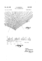
- Figure 1 is a diagrammatic view illustrating the equi-phase displacement pattern produced by three radio frequency transmitters and illustrating by means of dashed lines an alternate pattern resulting from changing the mode of operation of the transmitters:
- Figure 2 is a sequency diagram illustrating the i 3 time sequency characterising the alternating mode of operating the transmitting equipment
- Figure I3 is a black diagram illustrating the transmitting apparatus
- Figure 4 is a block diagram illustrating the receiving apparatus
- Figure 5 is a diagrammatic representation yof the phase indicators used in a receiving apparatus.
- Figure 6 is a wiring diagram illustrating one type of synchroniser circuit which may be employed with the receiving'apparatus shown in Figure 4.
- .transmitter A is operated at a frequency of 60 kc.
- transmitter kB ata'frequency of 80 kc.
- transmitter C at a frequency of 90 kc.
- phase comparison between the signals from transmitters A and B is eiected by converting both frequencies to a common reference frequency and measuring the phase relationbetween these two reference l signals of like frequency.
- the comparison or reference frequency for 'thev A and B transmissions would Itherefore be 2&0 lgc. while the reference frequency for the A and C transmissions will be 180 kc. a distance of 1 50 kilometers and locations A and C are spaced aparta distance of Y200 kilometers, there will be produced 240 individual lanes in each of the AB and AC patterns, each lane having a circumferential width'of 360 electrical degrees at the corresponding ⁇ corriparison or 'reference frequency.
- the lines I and 2 are representative of the lines'along which a zero degree phase difference is measured between the refrence signals of each of the two' sets. If the complete pattern were drawn there would be shown 240 of each of the lane boundary lines I ⁇ and 2. However, for the purpose of clarity in the drawing only every tenth lane boundary line has been shown.
- the das-hed lines-3 and 4 represent the field patterns resulting from proportionally changing the frequencies of each yof the three transmitters by an amount necessary gto reduce the spacing of each of'transmitters B and C from transmitter A by ⁇ one half wave length. This may be accomplishedby operating transmitter Aw at a frequency of 5,9% kc.,"transmitter BA at79% kc., and transmitter C at "895/8 kc. YAt these frequencies thev AB reference yfrequency is 239.18m. and the AC reference frequency is 179% kc.
- Each of the dashed line patterns. 3 and 4 therefore embracef239 full lanes and so distinguish from the 240 lanes characterisingthe solid ⁇ line pat-y tern. As isthe case with the selid lines I and 2 the dashed lines v:tand 4 represent every tenth lane boundary.
- phase measurement made rat a vpoint located on the dashed line 5 will diner by 180 degrees as between measurements made during the radiation of the normal or solid line pattern and measurements made during the radiation of ⁇ the .alternate or dashed line pattern.
- amount of shift measured ⁇ :between the normal and alternative modes -of transmitter operation is proportional .to the lane number for each lane assuming that the lane numbering is started at the point where the solid and dashed line patterns coincide (in the example illustrated ⁇ the patterns coincide onthebase lines 5 and 8,)
- the present-invention is directed to a method of operating the transmitting apparatus to alternatively radiate'the normal and alternative patterns and to a receiving apparatus for receiving these radiations and continuously indicating the lane identication as revealed by the vphase difference between the two sets of signals of the receiver Vwithin the lane thus identified.
- the Vtransmitting apparatus is operated alternately in accordance with a time'sequence such as that represented in Figure 2.
- the block areas 9 having a duration tN represent the normal mode of transmitter operation and the block areas "I0 having a time duration t. represent the periods of operation of the transmitters accordingto the alternative mode.
- the change-over time from the normal tor the alternativemode of: operation indicated by the period t1 is made short relative to the duration of transmitter operation, whereas the change over time t2 from alternative to normal is made approximately equal to the duration of the periods of transmitter operation.
- tml 15A and t2 may each have a duration of about 50 milliseconds while t1 may have a duration of about 1A0m illiseconds thus giving a total period T nof 160 milliseconds corresponding to arecurrence frequency-of 62.5 cycles per second.
- Figure 3l illustrates by means of a block dia- 5 gram the transmitting apparatus which is placed at locations A, B .and lC-.
- the transmitter at location A comprises a master transmitter employing a power amplifier I-I feedingan antenna I-2- at location A and arranged to be driven alternately from two oscillators i3 and I4 or other suitable sources of radio frequency energy at frequencies of 60 kc. and 59% kc. respectively.
- Oscillators i3 and 'I4 are each connected tothe power amplifier I ⁇ I through corresponding switchesfl and I6 which arearrangedto be operated alternately byv a suitablev timingA mechanism II in such a wayas to produce analternating Inode of yoperation suchv as has been described with reference to- Figure 2.
- Each of the transmitters situated at locations B and C are of the slave type and serve to receive signals from the master transmitter at location A' and to re radia te the receivedj signals at a different but harmonically related frequency and in a xed multiple p hase relation. Since i the two slave transmitters are identical, only that employedat location C will be described.
- the signals radiated from location A are picked up by a receiving aerial I8 which may comprise a loop antenna.
- the loop is coupled as shown at I9 to a frequency converter and reradiator serving to convert the 60 kc. input into a 90 kc. output.
- the output from apparatus 2l] is coupled as shown at 2
- a fixed multiple phase relation between the 90 kc.. signals radiated from antenna 22 and 60 kc. signals radiated from antenna l2 is obtained by the use of a phase discriminator and controller 23. This device operates to determine the multiple phase relation between 60 kc. signals picked up by the loop I8 and applied to the apparatus 23 through coupling device 24 and 90 kc.
- the device 23 serves also to produce a direct control potential the magnitude of which varies in correspondence with any changes in the phase relation determined by the phase discriminator.
- the variations in control potential are utilised in the apparatus 29 to so operate a phase shifting device as to shift the phase of the radiated 90 kc. signals in such direction and by such amount as to restore the multiple phase relation to the original value.
- the change in frequency radiated from location A from kc. to 59% kc. is accompanied by a change in radiation from location C lfrom 90 kc. to 89% kc.
- kc. signals are normally radiated from location B the change in master frequency from 60 kc. to 59% kc. automatically prod uces a change to 792/3 kc. in the frequency radiated from location B.
- FIG 4 a receiving apparatus which may be used to receive the radiations from the transmitting equipment above described and which operates to simultaneously give a lane identification and precise data as to the location of the receiver within the identified line.
- the signals radiated from each of locations A, B and C are received on an antenna 26 which is coupled to a kc. receiver 21, two 60 kc. receivers 28 and 29 and an 80 kc. receiver 30.
- a kc. receiver 21 two 60 kc. receivers 28 and 29 and an 80 kc. receiver 30.
- the output of receiver 21 is fed to a frequency converter 3l operating to produce an output frequency double the input frequency, that is, kc. during the normal mode of operation and 1791/4 kc. during the alternative mode of operation.
- the output of receiver 28 is coupled to a frequency converter 32 operating to treble the input frequency so as to produce normal and alternative output frequencies equal to those produced by the frequency converter 3l.
- the output of receiver 28 is' also coupled to a' frequency converter 33 operating to quadruple the input frequency soas to produce output sigg tors.
- the outputs from frequency converters 32, 33 and 34 are each divided and applied to vacuum tube gate circuits 3'
- the gate circuits are identical and each may comprise a pentode type of tube.
- the anodes andscreen grids are coupled through suitable coupling devices to a source of positive direct potential indication in Figure 4 by the arrow head bearing the sign
- the cathode of each tube is grounded and the l control grid of each tube is connected to the output of the frequency converter with which eachY gate circuit is associated.
- the suppressor grids of the stages 35, 38, 39, and 42 are connected in parallel and by means of a conductor 43 to a synchronizer circuit 44.
- the suppressor grids of gate stages 36, 3l, 40 and 4I are connected in parallel and by means of a conductor 45 to the synchronizer 44.
- rIhe synchroniser 44 is arranged to be controlled by the output ofthe receiver 29 which is rectified as by means of a rectifier 46 before being applied to the input of the synchroniser circuit 44.
- the synchronizer 44 operates to apply alternately to the conductors 43 and 45 a negative potential of sufficient magnitude to block the opera tion of the vacuum tubes the suppressor grids of which are connected to the respective conduc-
- Each of the gate circuits thus operates as a switch which is opened or closed in response to theabsence or presence of a negative control potentialV upon the associated control conductors 43 and 45.
- the anode of the gate tube 35 is coupled to one input circuit of a phase discriminator 4l, the other input circuit thereof being coupled to the anode of the gate tube 38.
- the anode of the gate tube 36 is coupled to one input circuit of another phase discriminator 48, the other input circuit of which is coupled to the anode of gate tube 3l.
- the anode of the gate tubes 39, 49, 4l, 42 are coupled to the input circuits of two other phase discriminators 49 and 50.
- phase discriminators 41, 48, 49 and 59 are each operatively connected to phase indicators 5
- phase indicator which is described in a co-pending application Serial No.v 612,984, filed August 27, 1945 by William J. OBrien Patent No. 499,326 granted Y grid of a gas tetrode 64.
- the phase indicator 52 includes a tubular rotating shaft .55 upon which is mounted a pointer 5S, for indicating on a suitable vdial or scale the phase relation between the two input signals of the phase ydiscriminator 48, these indications being representative of the location oi the vehicle Within one lane.
- the shaft 55. also comprises one input of a differential mechanism 51 the other inputy 58 of which comprises arotatable shaft of ⁇ the phase indicator 5
- the third shaft 59 of the diierential 51 is extended through the hollow shaft 55V and carries a pointer 60 for indicatingv on a suitable scale the diference between the angular positions of shafts 55 and V58.
- This angularposition is the phase difference at the location of the receiver between the solid line pattern ⁇ shown ,in Figure l and the dotted line pattern, so that the position Vof the pointer SS comprises an identification of the particular lane within which the receiver is located.
- a similar differential mechanism is used Ato inter-connect the phase discriminators 53 and 54 with their pointers and indicating dials.
- the receiver 28 rectifier 46 andy synchroniser 44 co-act to apply to the conductor 4?r a negative potential during the period tu represented by the block areas S on Figure 2, and during the periods tA represented by the block areas it on Eig-ure 2-.to apply ⁇ a negativewpotential to the control conductor t5..
- the discriminators 48 and 5D are operatively connected to the associated receivers by ⁇ the vaction vof Ythe gate stages 36, 31, 4&- and ill.. '
- the phase discriminators 41' and 4Q ⁇ are operatively connected to the receivers by the action of the gate stages 35, L.
- phase indicators 52 and 54 are intermittently energisedduring periods of normal transmission, and that phase indicators 5
- The-re v' is illustrated in Figure 6 a circuit which maybe used for the synchroniser 44.
- comprises the output of the rectifier et. This conductor is coupled through a condenser d2 and Vresistance '63 to the control The input 6
- the anodes of'each of the ⁇ tubes 64 and 61 are each coupled through coupling resistances 68 and 69 to asource of positive operating potential such as that represented by the battery 10.
- the cathodes and screen grids of each of the tubes are .inter-.connected and coupled to the .negative terminal of the battery 18 through cathode coupling resistances 1i and 1?..
- the control conductors 43 and 45shown on Figure 4 are connectedrespectively to the cathodes of the tubes G4 and v61.
- the battery 1B is grounded as indicated at 1,3 ata point intermediate the ends thereof so 4that there is normally applied tothe 8 cathodes of the tubes 6c and .61a potential which is negative. with respect to ground.
- Small by-.pass condensers 1'4 and 15 preferably inter-connect the grid and cathode of each tube, and the control grid of each tube is preferablyconnected through coupling resistances- 16 and 1:1 to a sourceof ⁇ negative bias potential (represented in Figure 6 'by ythe battery 18) the positive terminal of which is connected to the negative terminal of the battery 13.
- the bias battery 18 serves to normallyA hold the control grid of each of the tubes 64 and 61 suiciently negative with respect to Vthe cathode to maintain the tube in a non-conductive condition until the grid potential is shifted in the positive direction by an incoming signal to a point more positive lthan the critical grid potential ofthe tube.
- the anodeso f the two tubes are inter-connected through a commutating condenser 19.
- the time constant of the resist-ance 66 and condenser 15 ⁇ is made sulioiently long to prevent the grid potential of the tube S1 from rising to the critical value upon the application to Vthe conductor 5
- the time constant of the resistance t3 and condenser 1-4 is made sufnciently short to cause the tube 64 to conduct upon either aA short pulse or a long pulse.
- the radio frequency signals which are applied to the input of the receiver 29 have a time sequence such asis represented in Figure 2.
- the direct current output of the rectifier is exactly represented by the graph of Figure 2.
- the rectiiier V46 includes also a D. C. restoring circuit of conventional construction so that the signal which iswapplied to. the conductor 6
- tube 64 When the short pulse is applied ⁇ toconductor 6
- a radio navigational system in which the mode of operation of the transmitters is alternated between two different modes establishing two similar but unlike navigational patterns, and that there has been provided a receiving apparatus for receiving the transmitted signals together with means operating in an alternate fashion in synchronism with the alternations ofthe transmitting system to connect each set of phase indicators in circuit at the times the transmitting system is radiating the signals intended for those phase indicators.
- the described method of inter-connecting the two phase indicators serves to provide upon a single dial a continuous indication of the lane Within which a mobile vehicle is located concurrently with the precise location of the receiver within the thus identified lane.
- radio frequency transmitting means for radiating signals alternately establishing in repeating time cycles a normal and an alternative radio frequency field pattern of equi-phase displacement field contours, said normal pattern defining a given number of lanes and said alternative pattern defining a diierent number of lanes, said patterns being identically oriented in space; radio frequency receiving means for receiving said signals; two phase indicators operatively connected to said receiving means, one for said normal pattern and one for said alternative pattern; and switching means for rendering said indicators alternately operable in synchronism with said repeating time cycles.
- radio frequency transmitting means for radiating signals alternately establishing in repeating time cycles anormal and an alternative radio frequency eld pattern of equi-phase displacement i'leld contours, said normal pattern defining a given number of lanes and said alternative pattern dening a different number of lanes, said patterns being identically oriented in space; radio frequency receiving means for receiving said signals; two phase measuring means operatively connected to said receiving means, one for measuring the phase relations among the signals of said normal pattern, and the other for measuring the phase relations among the signals of said alternative pattern; switching means for rendering said two phase measuring means alternately operable in synchronism with said repeating time cycles; means for indicating the phase relatie-ns measured by one of said phase measuring means; and means for indicating the difference between the phase relations measured by said two phase measuring means.
- radio frequency transmitting means for radiating signals alternately establishing in repeating time cycles Va normal and an alternative radio frequency field pattern of (iii equi-phase displacement eld contours, said normal pattern deiining a given number of lanes and said alternative pattern defining a different number of lanes, said patterns being identically oriented in space; radio frequency receiving means for receiving said signals; two phase measuring means operatively connected to said receiving means, one formeasuring the phase relations among the signals of said normal pattern, and the other for measuring the phase 'relations among the signals of said alternative pattern; switching means for rendering said two phase measuring means alternately operable in synchrcnism with said repeating time cycles; means for indicating the phase relations measured by one of said phase measuring means; and means including a diierential mechanism connected between said two phase measuring means for indicating the difference between the phase relations measured by said two phase measuring means.
- a radio navigational aid transmitting system operating to radiate alternately in repeatingtime cycles two sets of radio frequency signals, each set comprising signals of unlike but harmonically related frequencies bearing a fixed multiple phase relation to each other, the signals of one of said sets differingslightly in frequency from the corresponding signals of the other set, toV establish a normal'and an alternative radio frequency eld pattern of equiphase displacement eld contours, said normal pattern defining a given number of lanes and said alternative pattern dening a diierent number of lanes, said patterns being identically oriented in space, a receiving apparatus comprising means for receiving each of said sets of signals; two phase measuring means operatively connected to said means for receiving for separately measuring the phase relations among the signals of each set; and means for rendering said two phase measuring means alternately operable in a repeating time cycle in synchronism with the alternate operation of said transmitting system.
- a radio navigational aid transmitting system operating to radiate ⁇ alternately in repeating time cycles two sets of radio frequency signals, each set comprising signals of unlike but harmonically related frequencies bearing a iixed multiple phase relation to each other, the signals of one of said sets diiering slightly in frequency from the corresponding signals of the other set, to establish a normal and an alternative radio frequency field pattern of equiphase displacement field contours, said normal pattern defining a given number of lanes and said alternative pattern defining a different' number of lanes, said patterns being identically oriented in space, a receiving apparatus comprising means for receiving each of said sets of signals; two phase measuring means operatively connected to said means for receiving for separately measuring the phase relations among the signals of each set; and means responsive to the alternations of said transmitting system for rendering said two phase measuring means alternately operable in a repeating time cycle in synchronism with the alternate operation of said transmitting system.
- a radio receiving apparatus the combination of: means for receiving ltwo sets of radio frequency signals, each set comprising signals of unlike but related frequencies bearing a xed 'multiple phase relation to veach other., the signals of Vonev set diiiering slightly in frequency from the corresponding signals of the other -.set, and said sets of signals being produced alternately in a repeating time cycle; two phase measuring means; gate lcircuit means connecting each phase measuring means to said receiver and including control means responsive to the application thereto of 'a control potential for operatively-opening said circuit; synchronizing means connected to said receiving means for producing two separate 'control potentials, one during the reception of the signals of vsaid one set and the other during the production .of signals of saidother set; and vmeans for applying said control potentials to said control means.
Landscapes
- Engineering & Computer Science (AREA)
- Computer Networks & Wireless Communication (AREA)
- Physics & Mathematics (AREA)
- General Physics & Mathematics (AREA)
- Radar, Positioning & Navigation (AREA)
- Remote Sensing (AREA)
- Radar Systems Or Details Thereof (AREA)
Description
A. R. GRENFELL RADIO NAVIGATIONAL AD Nov. 28, 1950 4 Sheets-Sheet 1 Filed July 28, 1947 Nov. 28, 1950 RADIO NAVIGATIONAL AID Filed July 28, 1947 4 Sheets-Sheet 2 O Smvf 7km/ITER C Aya ,(r- -Kmrm Saxe Fmr-(IP v 19A/D FNM t.
viene/yay [M14-rra? l Mya f- Kfm/922W A. R. GRENFELL 2,531,908 v Nov. 28, 1950 A. R. GRENFELL RADIO NAVIGATIONAL AID Filed July 28, 1947 4 Sheets-Sheet 5 SO KC A... vvv A Punselscmn.
ffm
[amarre-R hws Mtl/M @Istr/lv.
FImUE/rr [mme 80 ltr-24d lets/rn? Kant. 'n
faam? Imm Nov. 28, 1950 A. R. GRENFELL 2,531,908
RADIO NAVIGATIONAL AID Filed July 2s, 1947 4 sheets-sheet 4 Patented Nov. 28, 1950 UNITED RADIO N AVIGATIONAL AID Alexis Ren Grenfell, Stanmore, England, assignor to The Decca Record Company Limited,
London, Britain England, a corporation of Great Application July 28, 1947, Serial No. 764,155 In Great Britain August 12, 1946 7 Claims. l
This invention relates to radio navigational aids and has particular reference to a lane identication system for use with radio frequency navigational systems.
In a co-pending application Serial Number 612,986 filed by William J. OBrien on August 27, 1945 and assigned to the assignee of this application, there is described a lane identification system in which the identication is obtained by periodically altering the mode of operation of the transmitting equipment. that application it is explained that the direct phase measurement type of navigational aid operates to indicate the geographical location of a mobile Vehicle by measuring and indicating the multiple phase relations among a number of radio frequency signals of unlike but harmonically related frequencies radiated from a plurality of spaced points.
In order to achieve the requisite accuracy of indication, such a system is ordinarily operated with a considerable ambiguity, with the result that the same phase relation may be found in each of a considerable number of sectors or lanes (the term lane beingemployed to designate that sector-shaped area having av lateral width equal to 360 electrical degrees ophase displacement at the comparison frequency used in the system). In the normal operation of such a system the indicating device is provided with a register for counting and indicating the total of the number of lanes traversed during the motion of the vehicle so that if, at the time the system is placed in operation, the lane indicator is set manually to a reading corresponding to the then known location of the vehicle, the device will thereafter continue to indicate the correct lane andfraction thereof representative of the Vehiclev location regardless of the number of lanes crossed and regardless of the direction in which such crossings are made.
One of the disadvantages of such a system lies in the fact that under certain circumstances it is difficult to know the geographical location of the vehicle at the time the system comes into operation. This is particularly true in the case of long range ships or aircraft which come in to the operational field of the system from the outside. Under these circumstances the initial location of the vehicle is unknown and it is therefore impossible to set correctly the lane indicator.
In the above identified application it is eX- plained that by periodically proportionately shifting the frequencies of all of the radiated signals there is produced at the receiving appar-atusa phase shift. the. magnitude of which varies progressively from lane to lane around the navigational pattern. By this means the navigator of the mobile vehicle may determine the lane passing through his position and so accordingly set the lane indicators. Thereafter the system operates in the normal fashion and gives continuous and correct indications.
The present invention is directed to an improvement of the system disclosed in the above identified co-pending application and provides a method and apparatus serving to give a continuous indication which identifies the lane and at the same time gives precise navigational data as to the position of the vehicle within the identied lane.
It is therefore an object of this invention to provide a radio navigational aid of the direct phase measurement type which produces a continuous identification of the sector or lane within which a mobile vehicle is located concurrently with ag precise indication of the position of the vehicle within the identified lane.
It is another object of this invention to provide a navigational aid of the character set forth in: the preceding paragraph in which the mode of operation of the transmitters is continuously alternated between two modes and which the receiving apparatus isl operated in synchronism with said alternations.
It is also an object of this invention to provide a system of the'character hereinbefore referred to in which the receiving equipment includes two sets of phase measuring apparatus together with a switching means `for operatively energising said measuring apparatus alternately in synchronism with the alternate operation of the transmitting equipment.
It is a still further object of this invention to provide an apparatus of thel character set forth hereinbefore in which the change in mode of transmitter operation consists in a proportional shift in all frequencies transmitted by an amount equivalent to al change of one half wave length in transmitter spacing.
Other objects and advantages of this invention will be apparent from a study of the following specification read in connection with the accompanying drawings, wherein:
Figure 1 is a diagrammatic view illustrating the equi-phase displacement pattern produced by three radio frequency transmitters and illustrating by means of dashed lines an alternate pattern resulting from changing the mode of operation of the transmitters:
Figure 2 is a sequency diagram illustrating the i 3 time sequency characterising the alternating mode of operating the transmitting equipment;
Figure I3 is a black diagram illustrating the transmitting apparatus;
Figure 4 is a block diagram illustrating the receiving apparatus;
Figure 5 is a diagrammatic representation yof the phase indicators used in a receiving apparatus; and
Figure 6 is a wiring diagram illustrating one type of synchroniser circuit which may be employed with the receiving'apparatus shown in Figure 4.
Referring to the drawings, I have illustrated in Figure l by means of thesolid lines I and 2 the intersecting equi-phase displacement field patterns which may be obtained from three transmitters located for example, at locations A,-Band C and operated at different but harmonically related frequencies and in a fixed multiple phase relation to each other.
Forthis purpose of illustration it may be assumedthat .transmitter A is operated at a frequency of 60 kc., transmitter kB ata'frequency of 80 kc., and transmitter C at a frequency of 90 kc.
As will be explained hereinaften'the phase comparison between the signals from transmitters A and B is eiected by converting both frequencies to a common reference frequency and measuring the phase relationbetween these two reference l signals of like frequency. The comparison or reference frequency for 'thev A and B transmissions would Itherefore be 2&0 lgc. while the reference frequency for the A and C transmissions will be 180 kc. a distance of 1 50 kilometers and locations A and C are spaced aparta distance of Y200 kilometers, there will be produced 240 individual lanes in each of the AB and AC patterns, each lane having a circumferential width'of 360 electrical degrees at the corresponding `corriparison or 'reference frequency. -In Figure lg'the lines I and 2 are representative of the lines'along which a zero degree phase difference is measured between the refrence signals of each of the two' sets. If the complete pattern were drawn there would be shown 240 of each of the lane boundary lines I` and 2. However, for the purpose of clarity in the drawing only every tenth lane boundary line has been shown.
-In Figure 1 the das-hed lines-3 and 4 represent the field patterns resulting from proportionally changing the frequencies of each yof the three transmitters by an amount necessary gto reduce the spacing of each of'transmitters B and C from transmitter A by` one half wave length. This may be accomplishedby operating transmitter Aw at a frequency of 5,9% kc.,"transmitter BA at79% kc., and transmitter C at "895/8 kc. YAt these frequencies thev AB reference yfrequency is 239.18m. and the AC reference frequency is 179% kc. Each of the dashed line patterns. 3 and 4 therefore embracef239 full lanes and so distinguish from the 240 lanes characterisingthe solid` line pat-y tern. As isthe case with the selid lines I and 2 the dashed lines v:tand 4 represent every tenth lane boundary.
From an inspection of Figurefrlit will be seen that in proceeding in a counterclockwise direction around transmitter C, the dashed line pattern appears at a gradually increasing distance from the solid line patternxuntil the perpendicular bisector 5 of the AC base l-ine 6; is reached at which point the dashedrline coincides ywith the bisector and lies mid-way between adjacent solid If locations A andB are spaced apart 4 4 lines. As the rotation is continued the dashed lines gradually approach the solid lines next ahead until they coincide with the solid lines along the extension of the base line 6 beyond transmitter A. In the same way the dashed line pattern 4 leads the solid line pattern 2 until it coincides with the perpendicular bisector 'I of the base line l8 vwhich extends between transmitters A and B.
It is apparent that the phase measurement made rat a vpoint located on the dashed line 5 will diner by 180 degrees as between measurements made during the radiation of the normal or solid line pattern and measurements made during the radiation of `the .alternate or dashed line pattern. Similarly at other points in the field the amount of shift measured `:between the normal and alternative modes -of transmitter operation is proportional .to the lane number for each lane assuming that the lane numbering is started at the point where the solid and dashed line patterns coincide (in the example illustrated `the patterns coincide onthebase lines 5 and 8,)
The present-invention is directed to a method of operating the transmitting apparatus to alternatively radiate'the normal and alternative patterns and to a receiving apparatus for receiving these radiations and continuously indicating the lane identication as revealed by the vphase difference between the two sets of signals of the receiver Vwithin the lane thus identified.
In accordance with this vinvention the Vtransmitting apparatus is operated alternately in accordance with a time'sequence such as that represented in Figure 2. 'In Figure 2 the block areas 9 having a duration tN represent the normal mode of transmitter operation and the block areas "I0 having a time duration t. represent the periods of operation of the transmitters accordingto the alternative mode. The change-over time from the normal tor the alternativemode of: operation indicated by the period t1 is made short relative to the duration of transmitter operation, whereas the change over time t2 from alternative to normal is made approximately equal to the duration of the periods of transmitter operation. Preferably the times of operation are relatively short, for example, tml 15A and t2 may each have a duration of about 50 milliseconds while t1 may have a duration of about 1A0m illiseconds thus giving a total period T nof 160 milliseconds corresponding to arecurrence frequency-of 62.5 cycles per second.
Figure 3l illustrates by means of a block dia- 5 gram the transmitting apparatus which is placed at locations A, B .and lC-. The transmitter at location A comprises a master transmitter employ ing a power amplifier I-I feedingan antenna I-2- at location A and arranged to be driven alternately from two oscillators i3 and I4 or other suitable sources of radio frequency energy at frequencies of 60 kc. and 59% kc. respectively. Oscillators i3 and 'I4 are each connected tothe power amplifier I`I through corresponding switchesfl and I6 which arearrangedto be operated alternately byv a suitablev timingA mechanism II in such a wayas to produce analternating Inode of yoperation suchv as has been described with reference to- Figure 2.
Each of the transmitters situated at locations B and C are of the slave type and serve to receive signals from the master transmitter at location A' and to re radia te the receivedj signals at a different but harmonically related frequency and in a xed multiple p hase relation. Since i the two slave transmitters are identical, only that employedat location C will be described.
The signals radiated from location A are picked up by a receiving aerial I8 which may comprise a loop antenna. The loop is coupled as shown at I9 to a frequency converter and reradiator serving to convert the 60 kc. input into a 90 kc. output. The output from apparatus 2l] is coupled as shown at 2| to a transmitting antenna 22 situated at location C. A fixed multiple phase relation between the 90 kc.. signals radiated from antenna 22 and 60 kc. signals radiated from antenna l2 is obtained by the use of a phase discriminator and controller 23. This device operates to determine the multiple phase relation between 60 kc. signals picked up by the loop I8 and applied to the apparatus 23 through coupling device 24 and 90 kc. signals picked up by a small pick-up loop 25 situated near the antenna 22. The device 23 serves also to produce a direct control potential the magnitude of which varies in correspondence with any changes in the phase relation determined by the phase discriminator. The variations in control potential are utilised in the apparatus 29 to so operate a phase shifting device as to shift the phase of the radiated 90 kc. signals in such direction and by such amount as to restore the multiple phase relation to the original value.
For a complete description of the slave transmitter equipment reference should be had to the aforementioned co-pending application Serial No. 612,986.
It will be seen that since the signal radiated at location C is the ninth harmonic of the fundamental of which the signal radiated from location A is the sixth harmonic, the change in frequency radiated from location A from kc. to 59% kc. is accompanied by a change in radiation from location C lfrom 90 kc. to 89% kc. Similarly while kc. signals are normally radiated from location B the change in master frequency from 60 kc. to 59% kc. automatically prod uces a change to 792/3 kc. in the frequency radiated from location B.
There is illustrated in Figure 4 a receiving apparatus which may be used to receive the radiations from the transmitting equipment above described and which operates to simultaneously give a lane identification and precise data as to the location of the receiver within the identified line. The signals radiated from each of locations A, B and C are received on an antenna 26 which is coupled to a kc. receiver 21, two 60 kc. receivers 28 and 29 and an 80 kc. receiver 30. It will be understood that these receivers though normally tuned to the frequencies corresponding to the normal mode of transmitter operation are nevertheless sufficiently broad in their tuning to receive with equal facility the slightly different frequencies which are radiated during the alternative mode of transmitter operation.
The output of receiver 21 is fed to a frequency converter 3l operating to produce an output frequency double the input frequency, that is, kc. during the normal mode of operation and 1791/4 kc. during the alternative mode of operation. Similarly the output of receiver 28 is coupled to a frequency converter 32 operating to treble the input frequency so as to produce normal and alternative output frequencies equal to those produced by the frequency converter 3l.
The output of receiver 28 is' also coupled to a' frequency converter 33 operating to quadruple the input frequency soas to produce output sigg tors.
applied to each of two vacuum tube gate stages 35 and 36.
In a similar way the outputs from frequency converters 32, 33 and 34 are each divided and applied to vacuum tube gate circuits 3'|-38, 39-40, and lll-42. The gate circuits are identical and each may comprise a pentode type of tube. The anodes andscreen grids are coupled through suitable coupling devices to a source of positive direct potential indication in Figure 4 by the arrow head bearing the sign The cathode of each tube is grounded and the l control grid of each tube is connected to the output of the frequency converter with which eachY gate circuit is associated. The suppressor grids of the stages 35, 38, 39, and 42 are connected in parallel and by means of a conductor 43 to a synchronizer circuit 44. Similarly, the suppressor grids of gate stages 36, 3l, 40 and 4I are connected in parallel and by means of a conductor 45 to the synchronizer 44.
rIhe synchroniser 44 is arranged to be controlled by the output ofthe receiver 29 which is rectified as by means of a rectifier 46 before being applied to the input of the synchroniser circuit 44. As is explained in detail hereinafter, the synchronizer 44 operates to apply alternately to the conductors 43 and 45 a negative potential of sufficient magnitude to block the opera tion of the vacuum tubes the suppressor grids of which are connected to the respective conduc- Each of the gate circuits thus operates as a switch which is opened or closed in response to theabsence or presence of a negative control potentialV upon the associated control conductors 43 and 45. a
The anode of the gate tube 35 is coupled to one input circuit of a phase discriminator 4l, the other input circuit thereof being coupled to the anode of the gate tube 38. Similarly, the anode of the gate tube 36 is coupled to one input circuit of another phase discriminator 48, the other input circuit of which is coupled to the anode of gate tube 3l. In a similar way the anode of the gate tubes 39, 49, 4l, 42 are coupled to the input circuits of two other phase discriminators 49 and 50.
,The phase discriminators 41, 48, 49 and 59 are each operatively connected to phase indicators 5|,.52, 53 and 54 and each phase discriminator co-acts with its associated phase inf-` dicator in such a way as to cause the rotatable shaft of the phase indicator to assume an angular position which is representative of the phase angle between the two input signals of the phase discriminator. While phase discriminators and phase indicators of any suitable type may be employed a preference is expressed for the phase discriminator circuit which is described in a copending application Serial No. 612,991, filed August 27, 1945 by William J. OBrien Patent No. 2,500,200 granted March 14, 1950 and assigned to the assignee of this application, and a preference is expressed for the phase indicator which is described in a co-pending application Serial No.v 612,984, filed August 27, 1945 by William J. OBrien Patent No. 499,326 granted Y grid of a gas tetrode 64.
assises February 28, 1950. andi also assigned to. the asfv signee offthis application.
Asis shown in Figure l5, the phase indicator 52 includes a tubular rotating shaft .55 upon which is mounted a pointer 5S, for indicating on a suitable vdial or scale the phase relation between the two input signals of the phase ydiscriminator 48, these indications being representative of the location oi the vehicle Within one lane. The shaft 55. also comprises one input of a differential mechanism 51 the other inputy 58 of which comprises arotatable shaft of` the phase indicator 5|. The third shaft 59 of the diierential 51 is extended through the hollow shaft 55V and carries a pointer 60 for indicatingv on a suitable scale the diference between the angular positions of shafts 55 and V58. This angularposition is the phase difference at the location of the receiver between the solid line pattern `shown ,in Figure l and the dotted line pattern, so that the position Vof the pointer SS comprises an identification of the particular lane within which the receiver is located. A similar differential mechanism is used Ato inter-connect the phase discriminators 53 and 54 with their pointers and indicating dials.
The receiver 28 rectifier 46 andy synchroniser 44 co-act to apply to the conductor 4?r a negative potential during the period tu represented by the block areas S on Figure 2, and during the periods tA represented by the block areas it on Eig-ure 2-.to apply `a negativewpotential to the control conductor t5.. Thus, during periods of normal transmission the discriminators 48 and 5D are operatively connected to the associated receivers by `the vaction vof Ythe gate stages 36, 31, 4&- and ill.. 'Similarly, during the periods of alternative transmissions the phase discriminators 41' and 4Q `are operatively connected to the receivers by the action of the gate stages 35, L.
3E, '49 and 42. Thus vit will be seen that the phase indicators 52 and 54 are intermittently energisedduring periods of normal transmission, and that phase indicators 5| and 53 are intermittently venergised during the periods ofv alternative transmission. Since the repetition rate of the alternating transmissions is of the order of magnitude of I6i) cycles per second, the inertia of the mechanism associated with the phase indicators will be suidcient to cause the indicators to assume their proper indicating positions as reliably as though they Were continuously energised.
The-re v'is illustrated in Figure 6 a circuit which maybe used for the synchroniser 44. Input conductor 6| comprises the output of the rectifier et. This conductor is coupled through a condenser d2 and Vresistance '63 to the control The input 6| is also coupled through a condenser lS5 and resistance 66 to ja control grid of another gas tetrode 61. The anodes of'each of the `tubes 64 and 61 are each coupled through coupling resistances 68 and 69 to asource of positive operating potential such as that represented by the battery 10. The cathodes and screen grids of each of the tubes are .inter-.connected and coupled to the .negative terminal of the battery 18 through cathode coupling resistances 1i and 1?.. The control conductors 43 and 45shown on Figure 4 are connectedrespectively to the cathodes of the tubes G4 and v61. The battery 1B is grounded as indicated at 1,3 ata point intermediate the ends thereof so 4that there is normally applied tothe 8 cathodes of the tubes 6c and .61a potential which is negative. with respect to ground.
Small by-.pass condensers 1'4 and 15 preferably inter-connect the grid and cathode of each tube, and the control grid of each tube is preferablyconnected through coupling resistances- 16 and 1:1 to a sourceof` negative bias potential (represented in Figure 6 'by ythe battery 18) the positive terminal of which is connected to the negative terminal of the battery 13. The bias battery 18 serves to normallyA hold the control grid of each of the tubes 64 and 61 suiciently negative with respect to Vthe cathode to maintain the tube in a non-conductive condition until the grid potential is shifted in the positive direction by an incoming signal to a point more positive lthan the critical grid potential ofthe tube. The anodeso f the two tubes are inter-connected through a commutating condenser 19.
The time constant of the resist-ance 66 and condenser 15 `is made sulioiently long to prevent the grid potential of the tube S1 from rising to the critical value upon the application to Vthe conductor 5| of a short positive pulse but such that the grid potential will exceed the critical value when a positive pulse of long duration is applied to the conductor 61. The time constant of the resistance t3 and condenser 1-4 is made sufnciently short to cause the tube 64 to conduct upon either aA short pulse or a long pulse.
The radio frequency signals which are applied to the input of the receiver 29 have a time sequence such asis represented in Figure 2. When these signals are rectified by the rectier v4 6 the direct current output of the rectifier is exactly represented by the graph of Figure 2. The rectiiier V46 includes also a D. C. restoring circuit of conventional construction so that the signal which iswapplied to. the conductor 6| comprises a short positive pulse corresponding to the time t1 shown on Figure 2 followed by a long positive pulse corresponding to the time. tz shown on Figure, 2.
When the short pulse is applied `toconductor 6|, tube 64 is caused to conduct, thereby causing the cathode to be shifted in the positive direction to bring the conductor 43 substantially up to ground ptential. Since Vthe tube 6.1 does not viire upon the Vshort pulse the conductor 45 remains at cathode potential Which by reason of the grounding of thebattery 1D. intermediate its ends. is negative` with respect to ground. Upon the application of the long positive pulse to the conductor ti the tube 6.1 becomes conductive and byreason cf the commutating condenser 19, stops the conduction of tube 64. Therefore upon receipt of a long positive pulse conductor fis shifted in the positive direction to substantially groundpotential While conductor 43 shifts in the negative direction to a value suftcient to operate the, gate tubes shownin Figure 4. When the next short negative pulse is applied to Qonductor Cil, tube E4 is rendered conductive and t conduction of tube- 61- is stopped so as t0 restore the negati-ve potential to conductor 45 while shifting 'conductor 43 substantially to ground potential.
It will be noted that the use of the selected time constants for the input circuits of tubes 64 5.1 together with the short and long pulses corresponding to the times t1 and t2 ensures that the receiver is properly synchronised with the transmissions so that4 the phase indicators 52 and 54 are energised during the. periods of normal 5I and 53 are energised during the periods of alternative transmission.
From the foregoing it will be seen that there has been provided a radio navigational system in which the mode of operation of the transmitters is alternated between two different modes establishing two similar but unlike navigational patterns, and that there has been provided a receiving apparatus for receiving the transmitted signals together with means operating in an alternate fashion in synchronism with the alternations ofthe transmitting system to connect each set of phase indicators in circuit at the times the transmitting system is radiating the signals intended for those phase indicators. The described method of inter-connecting the two phase indicators serves to provide upon a single dial a continuous indication of the lane Within which a mobile vehicle is located concurrently with the precise location of the receiver within the thus identified lane.
While there has been shown and described the preferred embodiment of this invention, the same is netto be limited to the-details of construction shown and described herein, except as defined in the appended claims.
I claim:
l. In a radio frequency navigational aid, the combination of: radio frequency transmitting means for radiating signals alternately establishing in repeating time cycles a normal and an alternative radio frequency field pattern of equi-phase displacement field contours, said normal pattern defining a given number of lanes and said alternative pattern defining a diierent number of lanes, said patterns being identically oriented in space; radio frequency receiving means for receiving said signals; two phase indicators operatively connected to said receiving means, one for said normal pattern and one for said alternative pattern; and switching means for rendering said indicators alternately operable in synchronism with said repeating time cycles.
2. In a radio frequency navigational aid, the combination of radio frequency transmitting means for radiating signals alternately establishing in repeating time cycles anormal and an alternative radio frequency eld pattern of equi-phase displacement i'leld contours, said normal pattern defining a given number of lanes and said alternative pattern dening a different number of lanes, said patterns being identically oriented in space; radio frequency receiving means for receiving said signals; two phase measuring means operatively connected to said receiving means, one for measuring the phase relations among the signals of said normal pattern, and the other for measuring the phase relations among the signals of said alternative pattern; switching means for rendering said two phase measuring means alternately operable in synchronism with said repeating time cycles; means for indicating the phase relatie-ns measured by one of said phase measuring means; and means for indicating the difference between the phase relations measured by said two phase measuring means.
3. In a radio frequency navigational aid, the combination of: radio frequency transmitting means for radiating signals alternately establishing in repeating time cycles Va normal and an alternative radio frequency field pattern of (iii equi-phase displacement eld contours, said normal pattern deiining a given number of lanes and said alternative pattern defining a different number of lanes, said patterns being identically oriented in space; radio frequency receiving means for receiving said signals; two phase measuring means operatively connected to said receiving means, one formeasuring the phase relations among the signals of said normal pattern, and the other for measuring the phase 'relations among the signals of said alternative pattern; switching means for rendering said two phase measuring means alternately operable in synchrcnism with said repeating time cycles; means for indicating the phase relations measured by one of said phase measuring means; and means including a diierential mechanism connected between said two phase measuring means for indicating the difference between the phase relations measured by said two phase measuring means.
4. For use with a radio navigational aid transmitting system operating to radiate alternately in repeatingtime cycles two sets of radio frequency signals, each set comprising signals of unlike but harmonically related frequencies bearing a fixed multiple phase relation to each other, the signals of one of said sets differingslightly in frequency from the corresponding signals of the other set, toV establish a normal'and an alternative radio frequency eld pattern of equiphase displacement eld contours, said normal pattern defining a given number of lanes and said alternative pattern dening a diierent number of lanes, said patterns being identically oriented in space, a receiving apparatus comprising means for receiving each of said sets of signals; two phase measuring means operatively connected to said means for receiving for separately measuring the phase relations among the signals of each set; and means for rendering said two phase measuring means alternately operable in a repeating time cycle in synchronism with the alternate operation of said transmitting system.
5. For use with a radio navigational aid transmitting system operating to radiate` alternately in repeating time cycles two sets of radio frequency signals, each set comprising signals of unlike but harmonically related frequencies bearing a iixed multiple phase relation to each other, the signals of one of said sets diiering slightly in frequency from the corresponding signals of the other set, to establish a normal and an alternative radio frequency field pattern of equiphase displacement field contours, said normal pattern defining a given number of lanes and said alternative pattern defining a different' number of lanes, said patterns being identically oriented in space, a receiving apparatus comprising means for receiving each of said sets of signals; two phase measuring means operatively connected to said means for receiving for separately measuring the phase relations among the signals of each set; and means responsive to the alternations of said transmitting system for rendering said two phase measuring means alternately operable in a repeating time cycle in synchronism with the alternate operation of said transmitting system.
6. For use with a radio navigational aid transmitting system operating to radiate alternately in repeating time cycles two sets of radio fre- QUSBCY Signals, each set comprising signals of unlike but harmonicallyrelated frequencies bearing a fixed multipleplrase relation to each other, ithe .signals of one of said vsets differing :slightly in frequency from the corresponding signals of the `other set, Ito establish va normal and van alternative radio frequency eld `pattern of equifph-ase displacement eld contours, said normal ,pattern defining a given number of 'lanes and said alternative pattern den'ing a diiferent 'number of lanes, said `patterns being identically oriented in space, Va receiving apparatus comprising means for 'receiving each of said sets of signals; two phase measuring means operatively connected to vsaid means for receiving for separately measuring the phase relations among the signals :of `each set; means for rendering said two phase measuring means alternately operable in ya repeating time cycle in synchronism with the :alternate iopera-tion of said transmitting system; two indicating means; means directly connecting one :of said indicating means to one of said phase measuring means for directly vindicating the phase :relations among the signals of said one set; and diierential means connecting the other of said indicating means lto both of said phase measuring means for vindicating the difference b'etween the phase relations of said two sets of signals.
7. Ina radio receiving apparatus, the combination of: means for receiving ltwo sets of radio frequency signals, each set comprising signals of unlike but related frequencies bearing a xed 'multiple phase relation to veach other., the signals of Vonev set diiiering slightly in frequency from the corresponding signals of the other -.set, and said sets of signals being produced alternately in a repeating time cycle; two phase measuring means; gate lcircuit means connecting each phase measuring means to said receiver and including control means responsive to the application thereto of 'a control potential for operatively-opening said circuit; synchronizing means connected to said receiving means for producing two separate 'control potentials, one during the reception of the signals of vsaid one set and the other during the production .of signals of saidother set; and vmeans for applying said control potentials to said control means.
ALEXIS REN GRENFELL REFERENCES CITED The following references 'are of record in the file of this patent:
UNITED STATES PATENTS Number Name Date 1,942,262 Shanklin Jan. '2, 1934 2,144,203 Shanklin Jan. 17, 1939 2,324,314 Michel July 13, 1943 2,408,773 Goodall Oct. 8, 1946 2,426,454 Johnson Aug. 26, 1947 2,440,755 OBrien May 4, 1948
Applications Claiming Priority (1)
| Application Number | Priority Date | Filing Date | Title |
|---|---|---|---|
| GB2531908X | 1946-08-12 |
Publications (1)
| Publication Number | Publication Date |
|---|---|
| US2531908A true US2531908A (en) | 1950-11-28 |
Family
ID=10909322
Family Applications (1)
| Application Number | Title | Priority Date | Filing Date |
|---|---|---|---|
| US764155A Expired - Lifetime US2531908A (en) | 1946-08-12 | 1947-07-28 | Radio navigational aid |
Country Status (1)
| Country | Link |
|---|---|
| US (1) | US2531908A (en) |
Cited By (4)
| Publication number | Priority date | Publication date | Assignee | Title |
|---|---|---|---|---|
| US2616079A (en) * | 1948-06-08 | 1952-10-28 | Hastings Instr Company Inc | Navigation lane identification |
| US2728909A (en) * | 1948-06-03 | 1955-12-27 | Sperry Rand Corp | Non-ambiguous cycle matching radio navigation system |
| US2880413A (en) * | 1953-08-28 | 1959-03-31 | Seismograph Service Corp | Methods and apparatus for determining position |
| US2930037A (en) * | 1957-03-20 | 1960-03-22 | Seismograph Service Corp | Ambiguity resolution in radio location systems |
Citations (6)
| Publication number | Priority date | Publication date | Assignee | Title |
|---|---|---|---|---|
| US1942262A (en) * | 1933-03-22 | 1934-01-02 | John P Shanklin | Method for determining location in progress over a given area |
| US2144203A (en) * | 1937-09-23 | 1939-01-17 | John P Shanklin | Method for direct indication of position in a given area |
| US2324314A (en) * | 1941-11-13 | 1943-07-13 | Gen Electric | Electronic switch |
| US2408773A (en) * | 1942-03-31 | 1946-10-08 | Bell Telephone Labor Inc | Position determining system |
| US2426454A (en) * | 1942-05-27 | 1947-08-26 | Hazeltine Research Inc | Electronic switch |
| US2440755A (en) * | 1945-08-27 | 1948-05-04 | Decca Record Co Ltd | Radio-frequency navigation system |
-
1947
- 1947-07-28 US US764155A patent/US2531908A/en not_active Expired - Lifetime
Patent Citations (6)
| Publication number | Priority date | Publication date | Assignee | Title |
|---|---|---|---|---|
| US1942262A (en) * | 1933-03-22 | 1934-01-02 | John P Shanklin | Method for determining location in progress over a given area |
| US2144203A (en) * | 1937-09-23 | 1939-01-17 | John P Shanklin | Method for direct indication of position in a given area |
| US2324314A (en) * | 1941-11-13 | 1943-07-13 | Gen Electric | Electronic switch |
| US2408773A (en) * | 1942-03-31 | 1946-10-08 | Bell Telephone Labor Inc | Position determining system |
| US2426454A (en) * | 1942-05-27 | 1947-08-26 | Hazeltine Research Inc | Electronic switch |
| US2440755A (en) * | 1945-08-27 | 1948-05-04 | Decca Record Co Ltd | Radio-frequency navigation system |
Cited By (4)
| Publication number | Priority date | Publication date | Assignee | Title |
|---|---|---|---|---|
| US2728909A (en) * | 1948-06-03 | 1955-12-27 | Sperry Rand Corp | Non-ambiguous cycle matching radio navigation system |
| US2616079A (en) * | 1948-06-08 | 1952-10-28 | Hastings Instr Company Inc | Navigation lane identification |
| US2880413A (en) * | 1953-08-28 | 1959-03-31 | Seismograph Service Corp | Methods and apparatus for determining position |
| US2930037A (en) * | 1957-03-20 | 1960-03-22 | Seismograph Service Corp | Ambiguity resolution in radio location systems |
Similar Documents
| Publication | Publication Date | Title |
|---|---|---|
| US2144203A (en) | Method for direct indication of position in a given area | |
| US2208378A (en) | Continuously indicating radio compass | |
| US3242494A (en) | Position determination system | |
| US2402688A (en) | Meteorological telemetering system | |
| US2403890A (en) | Telemetering system | |
| US2208376A (en) | Rotating radio beacon | |
| US2531908A (en) | Radio navigational aid | |
| US2255659A (en) | Radiant energy distance determining system | |
| US2440755A (en) | Radio-frequency navigation system | |
| US3020545A (en) | Radio navigation system | |
| US2502662A (en) | Radio beacon system | |
| US2768374A (en) | Radio frequency surveying system | |
| US3303499A (en) | Radio location ranging system | |
| US2513317A (en) | Radio position determining system | |
| US3633204A (en) | Distance-measuring equipment | |
| US2438573A (en) | Equisignal radio beacon system | |
| US2513321A (en) | Radio location system | |
| US2728909A (en) | Non-ambiguous cycle matching radio navigation system | |
| US2587467A (en) | Position plotter for hyperbolic radio survey system | |
| US2483558A (en) | Area identification system | |
| US2563998A (en) | Direction finding apparatus | |
| US2551211A (en) | Radio position indicating system and apparatus | |
| US2871474A (en) | Radio location system | |
| US2717379A (en) | Radio navigation | |
| US2156297A (en) | Radio compass |