US2531784A - Piston ring - Google Patents
Piston ring Download PDFInfo
- Publication number
- US2531784A US2531784A US16055A US1605548A US2531784A US 2531784 A US2531784 A US 2531784A US 16055 A US16055 A US 16055A US 1605548 A US1605548 A US 1605548A US 2531784 A US2531784 A US 2531784A
- Authority
- US
- United States
- Prior art keywords
- ring
- wall
- piston
- expander
- compartment
- Prior art date
- Legal status (The legal status is an assumption and is not a legal conclusion. Google has not performed a legal analysis and makes no representation as to the accuracy of the status listed.)
- Expired - Lifetime
Links
- 229910052751 metal Inorganic materials 0.000 description 19
- 239000002184 metal Substances 0.000 description 19
- 230000006835 compression Effects 0.000 description 15
- 238000007906 compression Methods 0.000 description 15
- 230000002093 peripheral effect Effects 0.000 description 13
- 239000002131 composite material Substances 0.000 description 12
- 238000009740 moulding (composite fabrication) Methods 0.000 description 12
- 238000010276 construction Methods 0.000 description 6
- 238000007790 scraping Methods 0.000 description 4
- 238000004519 manufacturing process Methods 0.000 description 3
- 239000011253 protective coating Substances 0.000 description 3
- PXHVJJICTQNCMI-UHFFFAOYSA-N Nickel Chemical compound [Ni] PXHVJJICTQNCMI-UHFFFAOYSA-N 0.000 description 2
- 229910000639 Spring steel Inorganic materials 0.000 description 2
- 229910000831 Steel Inorganic materials 0.000 description 2
- 238000002485 combustion reaction Methods 0.000 description 2
- 238000007667 floating Methods 0.000 description 2
- 230000005923 long-lasting effect Effects 0.000 description 2
- 239000010959 steel Substances 0.000 description 2
- BHMLFPOTZYRDKA-IRXDYDNUSA-N (2s)-2-[(s)-(2-iodophenoxy)-phenylmethyl]morpholine Chemical compound IC1=CC=CC=C1O[C@@H](C=1C=CC=CC=1)[C@H]1OCCNC1 BHMLFPOTZYRDKA-IRXDYDNUSA-N 0.000 description 1
- 229910001018 Cast iron Inorganic materials 0.000 description 1
- VYZAMTAEIAYCRO-UHFFFAOYSA-N Chromium Chemical compound [Cr] VYZAMTAEIAYCRO-UHFFFAOYSA-N 0.000 description 1
- 102000004961 Furin Human genes 0.000 description 1
- 108090001126 Furin Proteins 0.000 description 1
- 229910045601 alloy Inorganic materials 0.000 description 1
- 239000000956 alloy Substances 0.000 description 1
- 230000015572 biosynthetic process Effects 0.000 description 1
- 229910052793 cadmium Inorganic materials 0.000 description 1
- BDOSMKKIYDKNTQ-UHFFFAOYSA-N cadmium atom Chemical compound [Cd] BDOSMKKIYDKNTQ-UHFFFAOYSA-N 0.000 description 1
- 229910052804 chromium Inorganic materials 0.000 description 1
- 239000011651 chromium Substances 0.000 description 1
- 238000007598 dipping method Methods 0.000 description 1
- 230000000694 effects Effects 0.000 description 1
- 238000009713 electroplating Methods 0.000 description 1
- 238000010438 heat treatment Methods 0.000 description 1
- 239000000463 material Substances 0.000 description 1
- 230000004048 modification Effects 0.000 description 1
- 238000012986 modification Methods 0.000 description 1
- 229910052759 nickel Inorganic materials 0.000 description 1
- 238000007747 plating Methods 0.000 description 1
- 239000010970 precious metal Substances 0.000 description 1
- 230000001681 protective effect Effects 0.000 description 1
- 239000011241 protective layer Substances 0.000 description 1
- 238000007789 sealing Methods 0.000 description 1
- 239000007787 solid Substances 0.000 description 1
- 230000008093 supporting effect Effects 0.000 description 1
Images

Classifications
-
- F—MECHANICAL ENGINEERING; LIGHTING; HEATING; WEAPONS; BLASTING
- F16—ENGINEERING ELEMENTS AND UNITS; GENERAL MEASURES FOR PRODUCING AND MAINTAINING EFFECTIVE FUNCTIONING OF MACHINES OR INSTALLATIONS; THERMAL INSULATION IN GENERAL
- F16J—PISTONS; CYLINDERS; SEALINGS
- F16J9/00—Piston-rings, e.g. non-metallic piston-rings, seats therefor; Ring sealings of similar construction
- F16J9/06—Piston-rings, e.g. non-metallic piston-rings, seats therefor; Ring sealings of similar construction using separate springs or elastic elements expanding the rings; Springs therefor ; Expansion by wedging
- F16J9/061—Piston-rings, e.g. non-metallic piston-rings, seats therefor; Ring sealings of similar construction using separate springs or elastic elements expanding the rings; Springs therefor ; Expansion by wedging using metallic coiled or blade springs
- F16J9/063—Strip or wire along the entire circumference
Definitions
- the present invention relates to piston-rings for internal-combustion engines, Diesel engines or the like, and it relates more particularly to compression and oil-control piston-rings.
- An object of the present invention is to provide new and improved compression or oil-control piston rings for internal-combustion engines, Diesel engines or the like.
- Another object of the present invention is to provide a trans-split compression piston ring which is relatively simple and, inexpensive to manufacture and which provides more positive, controlled and uniform pressure around its circumference with a minimum of fluttering at the free ends of the ring.
- Still another object of the present invention is to provide a two-piece compression piston-ring which is relatively more flexible than conventional cast compression rings whereby it provides more effective oil-scraping action during the downstroke of the piston and which is long-lasting and which can be easily installed and which can be used in piston grooves without accurately dimensioning the back or inner Wall of the ring relative to the piston-groove.
- compression piston-rings as trans-split cast members (formed of steel or cast-iron or the like) a separate expander-spring being disposed radially inward of the compression ring and being constructed and arranged to apply outward tension to the ring so as to keep it in contact with the cylinder-wall (the expander-spring being usually in the form of a radially-corrugated member which bottoms against the back or inner wall of the piston-groove, at each alternate corrugation, and which contacts the inner periphery of the piston-ring at the other corrugations). It has also been suggested in the past (for example in Patent 657,548) to construct a compression piston-ring 4of corrugated or coiled material having inherent tension. This construction, however, has not proven universally acceptable due to the diillculties involved in producing and maintaining uniform outward pressure as well as the relatively large cost and complexity of manufacture. i
- a piston-ring which has some of the advantages of ilexible rings (as for example higher oil-scraping ⁇ action) and which can be easily and inexpensively manufactured while providing a structure which is extremely long-lasting and which, at the same time, provides positive and uniform pressure all the way around its periphery.
- the novel piston-ring of the present invention is made up of an outer ring-portion which is of relatively flexible but non-resilient sheet-metal or the like, bent and folded into a generally closed channel cross-section which has limited axial flexibility and which presents an outermost generally-cylindrical axially-extending cylinder-contacting face; and an annular expander-spring of resilient metal or the like disposed generally in.a radial plane and within the channel of the outer ring-member; the said expander-spring being formed into a generally continuous S-shaped or reverselycurved radial configuration by notches ⁇ formed alternately at the outer and inner peripheries thereof.
- Figure 1 represents a perspective view of one embodiment of the present invention in assembled position; parts being broken away better to reveal the construction thereof.
- Figure 2 represents a plan view of the embodiment of Figure l. l
- Figure 3 represents a vertical cross-sectional view, on an enlarged scale, generally along the line 3-3 of Figure 2.
- Figure 4. represents a vertical cross-sectional view generally like that of Figure 3 but showing another embodiment of the present invention.
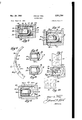
- Figure 5 represents a fragmentary plan view of still another embodiment of the present invention; parts being broken away better to reveal the construction thereof.
- Figure 6 represents a vertical cross-sectional view, on an enlarged scale, generally along the line -B of Figure 5.
- Figure '7 represents a fragmentary planjview; lyvrectangular cross-section, as indicated particshowlng the sheet-metal blank from which th ularly in' Figure 3; radially-extending slots I3 outer ring of Figures 5 and 61s made.
- r l y*and 34 being formed along the inner and outer Figurey 8 represents a vertical cross-sectionalv peripheries respectively in alternating relationview generally like that of Figure 6 but showingv 5 ship. a modified 'form of this embodiment.
- the thickness or axial dimension of the ex- Figure 9 represents a cross-sectional view genpander-spring 2
- can be installed within generally like that of Figure '7 but showing the the compartment 29 by spreading apart the free sheet-metal blank from which the outer ring of ends of the outer ring 20 and by similarly spread- Figure 9 is made.
- Figure v11 represents a cross-sectional view l5 2
- composite two-piece compression piston-ring The tension of the expander-spring 2
- be circumferentially spaced resilient trans-split annulus adapted to be insomewhat from the free ends 32 of the outer stalled within the outer ring 20 to provide resilring 20.
- the ring 20 is integrally formed from an elonthe unit can be quickly and easily installed by gated strip of thin fiat sheet-metal which is bent first manually spreading the outer rings sumto provide an outer peripheral cylinder-contactciently to pass over the piston, after which the ing face 22 which extends generally axially and unit will collapse within the piston-groove 24 conforms to the curvature of the cylinder 23 and,l thereafter, any conventional compression when the composite two-piece ring is installed tool can be used to install the piston 25 within within the groove 24 of a piston 25, as shown par- 35 the cylinder 23. ticularly in Figure 3.
- the ring 20 also includes a top side 26, piston-groove 24 so that, when the ring is maina curved inner wall 21 and a bottom side 28 tertained in continuous resilient contact with the minating in juxtaposition to the lower free end o cylinder-wall 23, as shown in Figure l, there is of the outer face 22 which, in this embodiment, an appreciable radial clearance between the inextends for the full axial dimension of the pistonner curved wall 21 of the ring 20 andthe back ⁇ 2
- the expander-spring 20 (which, in the smaller, in radial dimension, than said compart-I' 50 .installedposition, is compreed with its ends in ment 29 so that, when the outer periphery of the Ysubstantialabutment) provides a free-heating expander-spring 2
- al1 can obviously be of any other metal (or alloy) varound the circumference of the piston-ring. which can be deposited by electro-plating, sprayc ⁇ l ⁇ 4or ⁇ e'over,the internal supporting action of the ing, dipping, or other means. Among these are j'expander-spring-minimizes the fluttering of the cadmium, nickel, the precious metals, etc. v free ends 32A (flutteringl being an undesirable
- the ring 20 is formed as a trans-split annulus l tendency in conventional solid compression having a gap 3
- the protective coating I0 length of tempered spring-steel having a generalincreases the effective life of the piston-ring and v e factthat the pressure cf the expander- ⁇ scribed hereinabove.
- J--a in this embodiment, extends across the outer surface of the face 22-a and also across the end of the bottom side 28-a.
- this embodiment ernploys the shortened outer face 22--a, the elongated bottom side 28-a and the protective coating- Bil-a of Figure 4.
- the more-flexible constructions of Figures 6 and 8 are preferably used only in the second compression groove of the piston where oil-wiping action is more essential; the less-flexible constructions of Figures 1 and 4 being preferred for the first compression groove where the pressure-sealing action is more essential.
- novel piston-ring of the present invention is intended primarily as a compressionring (such as is usually employed in the uppermost two or three grooves of the piston), it can also be used as an oil-control piston-ring (in the lowermost groove or grooves of the piston) by simply forming a number of oil-drain openings therein, to permit the radial ow of oil from the cylinder-wall to the oil-drain passageways of the piston in conventional manner.
- openings 33 are formed in the outer face 22--b to provide an oil-control piston-ring; the outer face 22-b serving to wipe or scrape oil from the cylinder- 6 wall so that it passes through the openings i! and is then transferred radially through the inner compartment 23 (the transfer being facilitated by the capillary action of the adiacent top and bottom walls of the ring and of the expander 2
- l---lJ ⁇ can be formed from a sheet-metal blank wherein the slots 31 and the openings 33 are punched side by side.
- FIG 11 there is shown an oil-control piston-ring which is a modiiied form of that of Figure 9.
- the outer ring 20-c has its axially-extending portion 22-c slightly inwardly displaced so that an annular fold-line or rib ll is formed at the upper edge of the ring in axially-spaced relation to the free edge 42 oi the bottom wall 23-c.
- the rib 4I and the edge 42 thus provide a pair of annular axially-spaced cylinder-contacting lands or ribs for the purpose of more effectively wiping oil from the wall of the cylinder 23.
- the oil-drain openings take the form of notches 43 formed in the lowermost free edge of the axial wall 22--c.
- the cylinder-contacting lands 4l and 42 may be chrome-plated to reduce wear, in the manner described hereinabove.
- a composite two-piece piston-ring comprising ⁇ an integral trans-split ring formed from a. strip of relatively non-resilient sheet-metal folded to provide an outer peripheral wall, top and bottom walls and an inner wall forming a continuous enclosed annular compartment; and a non-bottoming resilient one-piece annular expander disposed within said compartment and providing generally uniform cutward tension around the circumference of said ring.
- a composite two-piece piston-ring comprising an integral trans-split ring formed from a strip of relatively non-resilient sheet-metal folded to provide an outer peripheral wall. top and bottom walls and an iner wall forming a continuous enclosed annular compartment, said outer wall having a generally cylindrical outer face said ring having a radial dimension in cross-section substantially greater than its axial dimension; and a non-bottoming resilient onepiece annular expander disposed within said cornpartment and providing generally uniform outward tension around the circumference of said ring.
- a composite two-piece piston-ring comprising an integral trans-split ring formed from a strip of non-resilient sheet-metal folded to provide an outer peripheral wall, top and bottom walls and an inner wall forming a continuous enclosed annular compartment, said outer wall extending in continuation of the top wall for generally the entire axial dimension of said ring; and a non-bottoming resilient one-piece annular expander disposed within said compartment and providing generally uniform outward tension around the circumference of said ring.
- a composite two-piece piston-ring comprising an integral trans-split ring formed from a strip of non-resilient sheet-metal folded to provide an outer peripheral wall, top and bottom walls and an inner wall forming a continuous enclosed annular compartment, said outer wall being formed by an axially-extending continuation of the top wall and by the free edge of the bottom wall; and a non-bottomng resilient onepiece annular expander disposed within said compartment and providing generally uniform outward tension around the circumference of said ring.
- a composite two-piece piston-ring comprising an integral trans-split ring formed from a strip of non-resilient sheet-metal folded to provide an outer peripheral wall, top and bottom walls and an inner wall forming a continuous enclosed annular compartment, said inner wall being provided with a plurality of circumferentially-distributed openings thereby to increase the flexibility of the ring; and a non-bottoming resilient one-piece annular expander disposed within said compartment and providing generally uniform outward tension around the circumference of said ring.
- a composite two-piece piston-ring comprising an integral trans-split ring formed from a strip of non-resilient,sheet-metal folded to provide an outer peripheral wall, top and bottom walls and an inner wall forming a continuous enclosed annular compartment, said outer peripheral wall providing a continuous cylindercontacting land, said inner wall being curved and being relieved by a plurality of circumferentiallydistributed slots thereby to increase the flexibility of the ring, said ring having a radial dimension in cross-section substantially greater than its axial dimension and a resilient free-floating radially-corrugated expander-spring disposed within said annular compartment and bearing against the outer wall thereof thereby to provide generally uniform outward tension around the circumference of said ring.
- a composite two-piece piston-ring comprising an integral trans-split ring formed from a strip of non-resilient sheet-metal folded to provide an outer peripheral wall, top and bottom walls and an inner wall forming a continuous enclosed annular compartment; and a resilient annular expander disposed within said compartment and providing generally uniform outward tension around the circumference of said ring, said expander having aplurality of slots formed alternately on the inner and outer peripheries thereof, said expander having an appreciably smaller radial dimension in cross-section than the radial dimension of said compartment.
- a composite two-piece piston-ring comprising an integral trans-split ring formed from a strip of non-resilient sheet-metal folded to provide anv outer peripheral wall, top and bottom walls and an inner wall forming a continuous enclosed annular compartment, said outer wall having a generally cylindrical outer face, said ring having a radial dimension in cross-section substantially greater than its axial dimension; and a resilient annular expander disposed within said compartment and providing generally unlform outward tension around the circumference of said ring, said expander having generally rectangular cross-section and having radial slots ⁇ formed alternately on the inner and outer pepressure around the circumference of said ring,
- said expander comprising a trans-split annulus disposed generally in a radial plane and having radial slots formed alternately on the inner and outer peripheries thereof, said expander having an appreciably smaller radial dimension in crosssection than the radial dimension of said compartment.
- a composite two-piece oil-control pistonring comprising an integral trans-split ring formed from a strip of non-resilient sheet-metal folded to provide an outer peripheral wall, top and bottom walls and an inner wall forming a continuous enclosed annular compartment, said outer wall having a recessed intermediate p0rtion thereby providing a pair of axially-spaced circumferential cylinder-contacting ribs, the inner wall and the recessed portion of the outer wall being provided with oil-drain openings to permit flow of oil radially through said ring; and a non-bottoming resilient one-piece annular expander disposed within said compartment and providing generally uniform outward pressure around the circumference of said ring.
- a composite two-piece oil-control pistonrlng comprising an integral trans-split ring formed from a strip of non-resilient sheet-metal folded to provide an outer peripheral wall, top and bottom walls and an inner wall for-ming a. continuous enclosed annular compartment, said outer wall having a recessed intermediate portion thereby providing a pair cf axially-spaced circumferential cylinder-contacting ribs, the inner wall and the recessed portion of the outer wall being provided with oil-drain openings to permit flow of oil radially through said ring; and a non-bottoming resilient one-piece annular expander disposed within said compartment and providing generally uniform outward pressure around the circumference of said ring, said expander comprising a trans-split annulus disposed generally in a radial plane and having radial slots formed alternately on .the inner and outer peripheries thereof, said expander having an appreciably smaller radial dimension in crosssectlon than the radial dimension ofsaid compartment.
Landscapes
- Engineering & Computer Science (AREA)
- General Engineering & Computer Science (AREA)
- Mechanical Engineering (AREA)
- Pistons, Piston Rings, And Cylinders (AREA)
Description
2 Sheets-Sheet 2 WML/? HSIA Si PIEPJ PISTON RING N ov. 28, 1950 Filed March 20, 1948 Patented Nov. 28, 1950 UNITED STATES PATENT i OFFICE ing Manufacturing Company, Pa., a corporation of Delaware Philadelphia,
i Application Marci; zo, 194s, serial No. 16,055
(ci. sos-4s) 11 Claims.
The present invention relates to piston-rings for internal-combustion engines, Diesel engines or the like, and it relates more particularly to compression and oil-control piston-rings.
An object of the present invention is to provide new and improved compression or oil-control piston rings for internal-combustion engines, Diesel engines or the like. Another object of the present invention is to provide a trans-split compression piston ring which is relatively simple and, inexpensive to manufacture and which provides more positive, controlled and uniform pressure around its circumference with a minimum of fluttering at the free ends of the ring.` Still another object of the present invention is to provide a two-piece compression piston-ring which is relatively more flexible than conventional cast compression rings whereby it provides more effective oil-scraping action during the downstroke of the piston and which is long-lasting and which can be easily installed and which can be used in piston grooves without accurately dimensioning the back or inner Wall of the ring relative to the piston-groove.
Other objects and advantages of the present inventionare apparent in the following detailed description, appended claims and accompanying drawings.
It has been customary in the past to construct compression piston-rings as trans-split cast members (formed of steel or cast-iron or the like) a separate expander-spring being disposed radially inward of the compression ring and being constructed and arranged to apply outward tension to the ring so as to keep it in contact with the cylinder-wall (the expander-spring being usually in the form of a radially-corrugated member which bottoms against the back or inner wall of the piston-groove, at each alternate corrugation, and which contacts the inner periphery of the piston-ring at the other corrugations). It has also been suggested in the past (for example in Patent 657,548) to construct a compression piston-ring 4of corrugated or coiled material having inherent tension. This construction, however, has not proven universally acceptable due to the diillculties involved in producing and maintaining uniform outward pressure as well as the relatively large cost and complexity of manufacture. i
According to the present invention, there has been perfected, for the first time, a piston-ring which has some of the advantages of ilexible rings (as for example higher oil-scraping `action) and which can be easily and inexpensively manufactured while providing a structure which is extremely long-lasting and which, at the same time, provides positive and uniform pressure all the way around its periphery.
Generally speaking, the novel piston-ring of the present invention is made up of an outer ring-portion which is of relatively flexible but non-resilient sheet-metal or the like, bent and folded into a generally closed channel cross-section which has limited axial flexibility and which presents an outermost generally-cylindrical axially-extending cylinder-contacting face; and an annular expander-spring of resilient metal or the like disposed generally in.a radial plane and within the channel of the outer ring-member; the said expander-spring being formed into a generally continuous S-shaped or reverselycurved radial configuration by notches `formed alternately at the outer and inner peripheries thereof.
Other features of the present invention include .the formation of slots on the inner periphery of the outer ring (to provide greater ilexibility without loss of compression) and the chrome-plating `of the outer peripheral cylindercontacting surface (to effect increase in wearing properties).
For the purpose of illustrating the invention, there are shown in the accompanying drawings forms thereof which are at present preferred, although it is to be understood that the lvarious instrumentalities of which the invention consists can be variously arranged and organized and that the invention is not limited to the precise arrangements and organizations of the instrumentalities as herein shown and described.
Referring to the accompanying drawings in which like reference characters indicate like characters throughout:
Figure 1 represents a perspective view of one embodiment of the present invention in assembled position; parts being broken away better to reveal the construction thereof.
Figure 2 represents a plan view of the embodiment of Figure l. l
Figure 3 represents a vertical cross-sectional view, on an enlarged scale, generally along the line 3-3 of Figure 2. y
Figure 4. represents a vertical cross-sectional view generally like that of Figure 3 but showing another embodiment of the present invention.
Figure 5 represents a fragmentary plan view of still another embodiment of the present invention; parts being broken away better to reveal the construction thereof.
Figure 6 represents a vertical cross-sectional view, on an enlarged scale, generally along the line -B of Figure 5.
Figure '7 represents a fragmentary planjview; lyvrectangular cross-section, as indicated particshowlng the sheet-metal blank from which th ularly in' Figure 3; radially-extending slots I3 outer ring of Figures 5 and 61s made. r l y*and 34 being formed along the inner and outer Figurey 8 represents a vertical cross-sectionalv peripheries respectively in alternating relationview generally like that of Figure 6 but showingv 5 ship. a modified 'form of this embodiment. The thickness or axial dimension of the ex- Figure 9 represents a cross-sectional view genpander-spring 2| vis very slightly less than the erally like that of Figure 3 but showing a modiaxial dimension of the compartment 29, while its fled construction wherein the ring is provided radial-dimension is appreciably less than that of with oil-drain openings. 10 the compartment 29, as mentioned above, so that Figure 10 represents afragmentary plan view the expander-spring 2| can be installed within generally like that of Figure '7 but showing the the compartment 29 by spreading apart the free sheet-metal blank from which the outer ring of ends of the outer ring 20 and by similarly spread- Figure 9 is made. ing-apart the free ends 35 of the expander-spring Figure v11 represents a cross-sectional view l5 2| and by inserting one of the free ends 35 withgenerally like that of Figure 9 but showing a furin the end of the compartment 23 and thereafter ther modified form of oil-control piston-ring. pushing the1 expander-spring until it is fully en- In one embodiment of the present invention closed within the outer ring 20, as indicated in shown generally in Figures 1-3, I may provide a Figure 2. composite two-piece compression piston-ring The tension of the expander-spring 2| will made up of an outer trans-split ring 20 of nonc then bring the assembled unit back more or less resilient flexible sheet-steel or the like to be hereto the original curvature. inafter described in detail and an expander- It is desirable that the free ends 35 of the exspring 2| of tempered spring-steel formed into a vander-Spring 2| be circumferentially spaced resilient trans-split annulus adapted to be insomewhat from the free ends 32 of the outer stalled within the outer ring 20 to provide resilring 20.
lent support therefor, as will be more fully de- With the expander-Spring 2| ,thus COntained sgribed herein, within the compartment 29 of the outer ring 20.
The ring 20 is integrally formed from an elonthe unit can be quickly and easily installed by gated strip of thin fiat sheet-metal which is bent first manually spreading the outer rings sumto provide an outer peripheral cylinder-contactciently to pass over the piston, after which the ing face 22 which extends generally axially and unit will collapse within the piston-groove 24 conforms to the curvature of the cylinder 23 and,l thereafter, any conventional compression when the composite two-piece ring is installed tool can be used to install the piston 25 within within the groove 24 of a piston 25, as shown par- 35 the cylinder 23. ticularly in Figure 3. As is apparent from Figure 1, the radial dimen- When viewed in vertical cross-section, as in sion of the outer ring 20 is less than that of the Figure 3, the ring 20 also includes a top side 26, piston-groove 24 so that, when the ring is maina curved inner wall 21 and a bottom side 28 tertained in continuous resilient contact with the minating in juxtaposition to the lower free end o cylinder-wall 23, as shown in Figure l, there is of the outer face 22 which, in this embodiment, an appreciable radial clearance between the inextends for the full axial dimension of the pistonner curved wall 21 of the ring 20 andthe back `2| and the curved inner wall 21 of the outer ring ring, Y wall 36 of the piston-groove 24.
As indicated particularly in Figure 3, the faces From the foregoingit is apparent that, when 22-26'-2'|28 provide an inner compartment or 45 installed on. a piston and within a cylinder, the chamber 29 which extends annularly throughout novel compression piston-ring of the present inthe entire circumferential dimension of the outer vention is maintained in resilient contact with ring 20 and which is adapted to receive thean; *thee-cylinder wall by the expander-spring 20. nular expander-spring 2| which is somewhat "Ifhatris, the expander-spring 20 (which, in the smaller, in radial dimension, than said compart-I' 50 .installedposition, is compreed with its ends in ment 29 so that, when the outer periphery of the Ysubstantialabutment) provides a free-heating expander-spring 2| contacts the inner surface of,y 3;." circumferentially generally uniform support for the face 22, there is a slight radial clearance ber 14theouterring'2|lwithout the need for bottomtween the inner periphery of the expander-spring ,l inggainstthe back wall 36 of the pistonl 4 c Y l 23. e relative flexibility'of the outer face The outer face 22 is chrome-plated as at-30 to improve the wearing properties of the ring...r 'The A spring-.aisapplied directly thereto,'a more positive protective layer 30, instead of being chromium v,controlledand uniform pressure is possible al1 can obviously be of any other metal (or alloy) varound the circumference of the piston-ring. which can be deposited by electro-plating, sprayc `l\4or`e'over,the internal supporting action of the ing, dipping, or other means. Among these are j'expander-spring-minimizes the fluttering of the cadmium, nickel, the precious metals, etc. v free ends 32A (flutteringl being an undesirable The ring 20 is formed as a trans-split annulus l tendency in conventional solid compression having a gap 3| which is closed when the troef-6 rings)-.\
led simultaneously herewith, is formed from a As mentioned above, the protective coating I0 length of tempered spring-steel having a generalincreases the effective life of the piston-ring and v e factthat the pressure cf the expander-` scribed hereinabove.
provides a long period of emcient operation at low cost.
In Figure 4, I have shown another embodiment of the present invention which generally resembles the embodiment of Figure 1, described above, except that the outer ring 2lia is slightly diiler- 4ently bent so that the bottom side 28-a extends all the way out to the outer periphery oi' the ring while the outer face 22-a has an axial dimension which is shorter than the face 22 by the thickness of the bottom side 28-a. In this way, the cylinder-contacting surface of the ring 23 is made up of the face 22-aand the free end of the side 23-a (the free end of the face 22-a being in juxtaposition with the upper surface of the bottom side 28--a, as indicated in Figure 4).
The protective coating 3|J--a, in this embodiment, extends across the outer surface of the face 22-a and also across the end of the bottom side 28-a.
The other elements of the ring of Figure 4 are identical with those described hereinabove in connection with the embodiment of Figure 1. The embodiment of Figure 4, however, provides slightly better oil-scraping action due to the slightly greater flexing permitted by the splitconstruction provided by the bottom side 2li-a.
In Figures 5 and 6, I have shown still another embodiment of the present invention which generally resembles that of Figure 4 except that the outer ring 2li-b is given somewhat greater ilexibility by providing a series of slots 31 on the curved inner wall 21-b; the slots 3l being punched off-center, in the fiat sheet-metal blank 38 of which the ring 2li-b is formed, as indicated in Figure 7.
As shown in Figure 6, this embodiment ernploys the shortened outer face 22--a, the elongated bottom side 28-a and the protective coating- Bil-a of Figure 4.
In Figure 8, I have shown a slightly modified form of the embodiments of Figures 6 and 7.
In Figure 8, there is shown a slight modification of the embodiment of Figures 5 and 6 wherein the longer face 22 (with the protective coating 30) and the shorter side 28 of Figure 3 are employed in conjunction with the slots 31 de- In this embodiment, it is apparent that in forming the blank from which the piston-ring is manufactured, the slots 31 are even further off-center (and are closer to the right-hand side of the blank when viewed as in Figure 7, by the thickness of the outer face 22).
The more-flexible constructions of Figures 6 and 8 are preferably used only in the second compression groove of the piston where oil-wiping action is more essential; the less-flexible constructions of Figures 1 and 4 being preferred for the first compression groove where the pressure-sealing action is more essential.
While the novel piston-ring of the present invention is intended primarily as a compressionring (such as is usually employed in the uppermost two or three grooves of the piston), it can also be used as an oil-control piston-ring (in the lowermost groove or grooves of the piston) by simply forming a number of oil-drain openings therein, to permit the radial ow of oil from the cylinder-wall to the oil-drain passageways of the piston in conventional manner.
Thus. in Figure 9, I have shown a modiilcation of the embodiment of Figure 8 wherein openings 33 are formed in the outer face 22--b to provide an oil-control piston-ring; the outer face 22-b serving to wipe or scrape oil from the cylinder- 6 wall so that it passes through the openings i! and is then transferred radially through the inner compartment 23 (the transfer being facilitated by the capillary action of the adiacent top and bottom walls of the ring and of the expander 2|) and then through the slots 31 and into the oil-drain passageways It which extend :radially inwardly from the cylinder-groove 24-a..
As shown in Figure 10, the ring 2|l---lJ` can be formed from a sheet-metal blank wherein the slots 31 and the openings 33 are punched side by side.
In Figure 11 there is shown an oil-control piston-ring which is a modiiied form of that of Figure 9. In this embodiment, the outer ring 20-c has its axially-extending portion 22-c slightly inwardly displaced so that an annular fold-line or rib ll is formed at the upper edge of the ring in axially-spaced relation to the free edge 42 oi the bottom wall 23-c. The rib 4I and the edge 42 thus provide a pair of annular axially-spaced cylinder-contacting lands or ribs for the purpose of more effectively wiping oil from the wall of the cylinder 23.
In the embodiment of Figure 11, the oil-drain openings take the form of notches 43 formed in the lowermost free edge of the axial wall 22--c.
The cylinder-contacting lands 4l and 42 may be chrome-plated to reduce wear, in the manner described hereinabove.
While I prefer to employ the expander 2l, it is apparent that other types of non-bottoming free-floating expander-springs could be used within the compartment 23 of the ring 20 (or 20-a or 2lib or 2ll-`c). Thus, for example, an axially-corrugated continuous annulus of resilient sheet-metal or the like. like that shown in Patent 2,293,450, could be employed within the compartment 23 of the outer ring 20 in order to provide resilient support therefor.
The present invention may be embodied in other specic forms Without departing from the spirit or essential attributes thereof, and it is therefore desired that the present embodiments be considered in all respects as illustrative and not restrictive, reference being had to 'the appended claims rather than to the foregoing description to indicate the scope of the invention.
Having thus described my invention, I claim as new and desire to protect by Letters Patent:
1. A composite two-piece piston-ring comprising` an integral trans-split ring formed from a. strip of relatively non-resilient sheet-metal folded to provide an outer peripheral wall, top and bottom walls and an inner wall forming a continuous enclosed annular compartment; and a non-bottoming resilient one-piece annular expander disposed within said compartment and providing generally uniform cutward tension around the circumference of said ring.
2. A composite two-piece piston-ring comprising an integral trans-split ring formed from a strip of relatively non-resilient sheet-metal folded to provide an outer peripheral wall. top and bottom walls and an iner wall forming a continuous enclosed annular compartment, said outer wall having a generally cylindrical outer face said ring having a radial dimension in cross-section substantially greater than its axial dimension; and a non-bottoming resilient onepiece annular expander disposed within said cornpartment and providing generally uniform outward tension around the circumference of said ring.
il.A A composite two-piece piston-ring comprising an integral trans-split ring formed from a strip of non-resilient sheet-metal folded to provide an outer peripheral wall, top and bottom walls and an inner wall forming a continuous enclosed annular compartment, said outer wall extending in continuation of the top wall for generally the entire axial dimension of said ring; and a non-bottoming resilient one-piece annular expander disposed within said compartment and providing generally uniform outward tension around the circumference of said ring.
4. A composite two-piece piston-ring comprising an integral trans-split ring formed from a strip of non-resilient sheet-metal folded to provide an outer peripheral wall, top and bottom walls and an inner wall forming a continuous enclosed annular compartment, said outer wall being formed by an axially-extending continuation of the top wall and by the free edge of the bottom wall; and a non-bottomng resilient onepiece annular expander disposed within said compartment and providing generally uniform outward tension around the circumference of said ring.
5. A composite two-piece piston-ring comprising an integral trans-split ring formed from a strip of non-resilient sheet-metal folded to provide an outer peripheral wall, top and bottom walls and an inner wall forming a continuous enclosed annular compartment, said inner wall being provided with a plurality of circumferentially-distributed openings thereby to increase the flexibility of the ring; and a non-bottoming resilient one-piece annular expander disposed within said compartment and providing generally uniform outward tension around the circumference of said ring.
6. A composite two-piece piston-ring comprising an integral trans-split ring formed from a strip of non-resilient,sheet-metal folded to provide an outer peripheral wall, top and bottom walls and an inner wall forming a continuous enclosed annular compartment, said outer peripheral wall providing a continuous cylindercontacting land, said inner wall being curved and being relieved by a plurality of circumferentiallydistributed slots thereby to increase the flexibility of the ring, said ring having a radial dimension in cross-section substantially greater than its axial dimension and a resilient free-floating radially-corrugated expander-spring disposed within said annular compartment and bearing against the outer wall thereof thereby to provide generally uniform outward tension around the circumference of said ring.
7. A composite two-piece piston-ring comprising an integral trans-split ring formed from a strip of non-resilient sheet-metal folded to provide an outer peripheral wall, top and bottom walls and an inner wall forming a continuous enclosed annular compartment; and a resilient annular expander disposed within said compartment and providing generally uniform outward tension around the circumference of said ring, said expander having aplurality of slots formed alternately on the inner and outer peripheries thereof, said expander having an appreciably smaller radial dimension in cross-section than the radial dimension of said compartment.
8.- A composite two-piece piston-ring comprising an integral trans-split ring formed from a strip of non-resilient sheet-metal folded to provide anv outer peripheral wall, top and bottom walls and an inner wall forming a continuous enclosed annular compartment, said outer wall having a generally cylindrical outer face, said ring having a radial dimension in cross-section substantially greater than its axial dimension; and a resilient annular expander disposed within said compartment and providing generally unlform outward tension around the circumference of said ring, said expander having generally rectangular cross-section and having radial slots `formed alternately on the inner and outer pepressure around the circumference of said ring,
said expander comprising a trans-split annulus disposed generally in a radial plane and having radial slots formed alternately on the inner and outer peripheries thereof, said expander having an appreciably smaller radial dimension in crosssection than the radial dimension of said compartment.
10. A composite two-piece oil-control pistonring comprising an integral trans-split ring formed from a strip of non-resilient sheet-metal folded to provide an outer peripheral wall, top and bottom walls and an inner wall forming a continuous enclosed annular compartment, said outer wall having a recessed intermediate p0rtion thereby providing a pair of axially-spaced circumferential cylinder-contacting ribs, the inner wall and the recessed portion of the outer wall being provided with oil-drain openings to permit flow of oil radially through said ring; and a non-bottoming resilient one-piece annular expander disposed within said compartment and providing generally uniform outward pressure around the circumference of said ring.
11. A composite two-piece oil-control pistonrlng comprising an integral trans-split ring formed from a strip of non-resilient sheet-metal folded to provide an outer peripheral wall, top and bottom walls and an inner wall for-ming a. continuous enclosed annular compartment, said outer wall having a recessed intermediate portion thereby providing a pair cf axially-spaced circumferential cylinder-contacting ribs, the inner wall and the recessed portion of the outer wall being provided with oil-drain openings to permit flow of oil radially through said ring; and a non-bottoming resilient one-piece annular expander disposed within said compartment and providing generally uniform outward pressure around the circumference of said ring, said expander comprising a trans-split annulus disposed generally in a radial plane and having radial slots formed alternately on .the inner and outer peripheries thereof, said expander having an appreciably smaller radial dimension in crosssectlon than the radial dimension ofsaid compartment.
HSIA-SI PIEN.
(References cn following page) REFERENCES CITED Number The following references are of record in the me 0f this mnt: 2317I580 UNITED STATES PA'I'ENTS I Number Name Date Number 1,741,436 Baule Dec. 31. 1929 1,424 1,958,014 Fink Apr. 24. `1934 847.167
Name Date Crawford Apr. 29, 1941 Smith July 21. 1942 Bauer Apr. 27, 1943 `FOREIGN PATENTS Countryf Date GreatBntain June 24, 1858 France4 Oct. 4, 1939
Priority Applications (1)
| Application Number | Priority Date | Filing Date | Title |
|---|---|---|---|
| US16055A US2531784A (en) | 1948-03-20 | 1948-03-20 | Piston ring |
Applications Claiming Priority (1)
| Application Number | Priority Date | Filing Date | Title |
|---|---|---|---|
| US16055A US2531784A (en) | 1948-03-20 | 1948-03-20 | Piston ring |
Publications (1)
| Publication Number | Publication Date |
|---|---|
| US2531784A true US2531784A (en) | 1950-11-28 |
Family
ID=21775133
Family Applications (1)
| Application Number | Title | Priority Date | Filing Date |
|---|---|---|---|
| US16055A Expired - Lifetime US2531784A (en) | 1948-03-20 | 1948-03-20 | Piston ring |
Country Status (1)
| Country | Link |
|---|---|
| US (1) | US2531784A (en) |
Cited By (3)
| Publication number | Priority date | Publication date | Assignee | Title |
|---|---|---|---|---|
| US20060123733A1 (en) * | 2004-12-09 | 2006-06-15 | Moody Donald R | Roof truss |
| US20070080502A1 (en) * | 2003-10-30 | 2007-04-12 | Holger Franz | Oil control ring for pistons of internal combustion engines |
| US20100084822A1 (en) * | 2008-10-08 | 2010-04-08 | Andreas Gimsa | Two-Part Piston Rod Gasket |
Citations (6)
| Publication number | Priority date | Publication date | Assignee | Title |
|---|---|---|---|---|
| US1741436A (en) * | 1923-04-21 | 1929-12-31 | Clifford T Raule | Hollow packing ring for pistons |
| US1956014A (en) * | 1924-11-22 | 1934-04-24 | Chemical Treat Company Inc | Wearing part for internal combustion engines |
| FR847167A (en) * | 1938-12-06 | 1939-10-04 | thermodynamic element for seals | |
| US2239703A (en) * | 1939-07-31 | 1941-04-29 | Thompson Prod Inc | Flexible piston ring |
| US2290499A (en) * | 1940-02-16 | 1942-07-21 | Mc Quay Norris Mfg Company | Piston ring |
| US2317580A (en) * | 1940-01-06 | 1943-04-27 | Hastings Mfg Co | Composite piston ring |
-
1948
- 1948-03-20 US US16055A patent/US2531784A/en not_active Expired - Lifetime
Patent Citations (6)
| Publication number | Priority date | Publication date | Assignee | Title |
|---|---|---|---|---|
| US1741436A (en) * | 1923-04-21 | 1929-12-31 | Clifford T Raule | Hollow packing ring for pistons |
| US1956014A (en) * | 1924-11-22 | 1934-04-24 | Chemical Treat Company Inc | Wearing part for internal combustion engines |
| FR847167A (en) * | 1938-12-06 | 1939-10-04 | thermodynamic element for seals | |
| US2239703A (en) * | 1939-07-31 | 1941-04-29 | Thompson Prod Inc | Flexible piston ring |
| US2317580A (en) * | 1940-01-06 | 1943-04-27 | Hastings Mfg Co | Composite piston ring |
| US2290499A (en) * | 1940-02-16 | 1942-07-21 | Mc Quay Norris Mfg Company | Piston ring |
Cited By (6)
| Publication number | Priority date | Publication date | Assignee | Title |
|---|---|---|---|---|
| US20070080502A1 (en) * | 2003-10-30 | 2007-04-12 | Holger Franz | Oil control ring for pistons of internal combustion engines |
| US7306234B2 (en) * | 2003-10-30 | 2007-12-11 | Mahle Gmbh | Oil control ring for pistons of internal combustion engines |
| US20080295442A1 (en) * | 2003-12-09 | 2008-12-04 | Nucon Steel Corporation | Roof truss |
| US20080295448A1 (en) * | 2003-12-09 | 2008-12-04 | Nucon Steel Corporation | Roof truss |
| US20060123733A1 (en) * | 2004-12-09 | 2006-06-15 | Moody Donald R | Roof truss |
| US20100084822A1 (en) * | 2008-10-08 | 2010-04-08 | Andreas Gimsa | Two-Part Piston Rod Gasket |
Similar Documents
| Publication | Publication Date | Title |
|---|---|---|
| US3066943A (en) | Piston ring | |
| US2695825A (en) | Piston ring assembly | |
| JP3957778B2 (en) | Piston rod sealing device | |
| US4099730A (en) | Piston ring construction | |
| US2452503A (en) | Piston ring | |
| US2554289A (en) | Piston ring | |
| US2614899A (en) | Piston ring | |
| US2233579A (en) | Fabricated packing | |
| US2531784A (en) | Piston ring | |
| US3323807A (en) | Piston ring | |
| US1879855A (en) | Piston rod packing | |
| US1707035A (en) | Piston ring | |
| US2306838A (en) | Slush pump piston | |
| US2668088A (en) | Piston ring and expander therefor | |
| US2202802A (en) | Piston ring | |
| US3195903A (en) | Piston oil control ring | |
| US2635932A (en) | Piston ring assembly for the pistons of internal-combustion engines | |
| US2585952A (en) | Piston packing ring | |
| US1911736A (en) | Piston ring | |
| US2220948A (en) | Piston ring | |
| US2635933A (en) | Piston ring construction | |
| US2439702A (en) | Piston ring | |
| US3430968A (en) | Piston ring assembly | |
| US2579698A (en) | Piston ring | |
| US2297104A (en) | Piston ring |