US2528362A - Axially shifting type tire removing device - Google Patents
Axially shifting type tire removing device Download PDFInfo
- Publication number
- US2528362A US2528362A US125947A US12594749A US2528362A US 2528362 A US2528362 A US 2528362A US 125947 A US125947 A US 125947A US 12594749 A US12594749 A US 12594749A US 2528362 A US2528362 A US 2528362A
- Authority
- US
- United States
- Prior art keywords
- tire
- secured
- base
- lever
- tool
- Prior art date
- Legal status (The legal status is an assumption and is not a legal conclusion. Google has not performed a legal analysis and makes no representation as to the accuracy of the status listed.)
- Expired - Lifetime
Links
- 239000011324 bead Substances 0.000 description 9
- 238000010276 construction Methods 0.000 description 2
- 239000002184 metal Substances 0.000 description 2
- 238000012986 modification Methods 0.000 description 2
- 230000004048 modification Effects 0.000 description 2
- 238000005096 rolling process Methods 0.000 description 2
- 241000252073 Anguilliformes Species 0.000 description 1
- 229910000831 Steel Inorganic materials 0.000 description 1
- 229960001948 caffeine Drugs 0.000 description 1
- 230000000994 depressogenic effect Effects 0.000 description 1
- 238000003780 insertion Methods 0.000 description 1
- 235000000396 iron Nutrition 0.000 description 1
- 238000003825 pressing Methods 0.000 description 1
- 230000000284 resting effect Effects 0.000 description 1
- 239000010959 steel Substances 0.000 description 1
- RYYVLZVUVIJVGH-UHFFFAOYSA-N trimethylxanthine Natural products CN1C(=O)N(C)C(=O)C2=C1N=CN2C RYYVLZVUVIJVGH-UHFFFAOYSA-N 0.000 description 1
- 238000003466 welding Methods 0.000 description 1
Images
Classifications
-
- B—PERFORMING OPERATIONS; TRANSPORTING
- B60—VEHICLES IN GENERAL
- B60C—VEHICLE TYRES; TYRE INFLATION; TYRE CHANGING; CONNECTING VALVES TO INFLATABLE ELASTIC BODIES IN GENERAL; DEVICES OR ARRANGEMENTS RELATED TO TYRES
- B60C25/00—Apparatus or tools adapted for mounting, removing or inspecting tyres
- B60C25/01—Apparatus or tools adapted for mounting, removing or inspecting tyres for removing tyres from or mounting tyres on wheels
- B60C25/02—Tyre levers or the like, e.g. hand-held
Definitions
- This invention relates tothe tools; and more particularly to a device adapted toremove tires from tra'ctor or'truck wh'eels.
- Tires which have been mounted on therim of a wheel for a substantial length of time will-adhere to therim so as'to mak'e it very difficult'to' release the tire from the rim,,since therims of the wheels are usually m'ade from-steel andthereis a tendency for the adjacent metal to rustand forma bond between the "tire bead and the rimf
- Anobject of this invention is'to provide-a device which is especially adaptable for removingtires from what iscommonly known as drop center rims onwhich pneumatic tires are used, while b'eingequally adaptable for' rims having lock rings.
- ' Afurther'object of the invention is to provide a'" tire tool which is equally adaptable for removing tires from wheel rimson which the tires are mounted. These 'tires may be of solidrub her or pneumatic.
- Yet another object of the invention is to pro vide a-tire tool which is adjustable -iorremoving varioussize tires-from rims while providing a desired leverage for-tires of greater size
- a further object of the invention is to' provide'meansfor"more readily rotating atireon a wheelabout thebase of the tire tool so that the tire-engaging member maybe more easily” capableof performing its several and continuous operations on the tire.
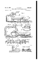
- Figure 2 is a side elevational view of the tire 'toorin an-enlargedscale showing'thetire tool in 2 operative engagement with the tire on a wheel vofa vehicle, the wheel being shown in cross-- section for the greater detail thereof;
- Figure 3 is a partial topplan view of theembodimentshown in Figure 2;
- num'eral2d is formed from a pairof spaced "members 22J' and 24 which are -positioned oneither side ofthe plate-"161'
- A-lever bar'28" is pinned asat fitl tcthe other end'of the spaced members-22 and 2d, and a socket is formed by the top and bottom pieces Hand '34, and the center piece 36 which-are welded. or otherwise secured tothe spaced plates.
- a readilyremovable pin -38*havingfa pull ring 40 is used to pivotally mount a tire-engaging member llbetween th'e'spaced members Hand 24.
- the tir e engagingmember- 42 extends through the guide 18 and is'formed with aspoon 44 for-insertion under the rim of the tire.
- This tire-engaging member has a plurality of apertures ABth'erethrough for selective adjustment of themember 42 for different size tires.
- the bottom flange 48 of the I beam from which the base is made are a plurality of brackets having base plates 56 andangularly disposed upright plates 52 having notches-54*for reception of shaft ends 56 0f rollers '58 *whi'ch'- are mounted between two spaced brackets;
- eyes 66 On either side of the'ba'se Ill" extend eyes 66;
- another pair of eyes" 62 are secured adjacent the end 65 of the base.
- a slide 66-" is placed upon' the baselll.
- Welded to-an-end of the slide 66' is a tube 68 which is preferablyo'fsquareshape.
- An L-shaped mem-' "ber is slidably emplaced in the tube 68;
- a clamp comprising a bar 12 having a cylinder 14 secured at one end is provided with a pair of hooks 16 which are pinned as at T8 eccentrically dislocated from the center of the cylinder 14.
- the hooks are positioned within the eyes 62, and upon suitable rotation of the bar 12, the slide 66 may be substantially rigidly clamped tothe base 10.
- This tire tool is used to break the bead of the tire by forcing the bead downwards off the rim or wheel, as best shown in Figure 1.
- the wheel with the tire thereon is placed upon a jig 80 which has been previously placed upon base 10.
- the spoon 44 of the tire-engaging member 42 is positioned on the side wall of the tire so that upon depression of the lever 28, th spoon will force the bead of the tire downwards off the rim onto jig 80.
- the entire wheel and jig can be quite easily rotated to another position for engagement by the spoon 44 due to the rolling engagement by rollers 58. 7
- the L-shaped member 70 is used to rigidly hold the tire against vertical movement when the lever 28 is depressed in the operation shown in Figure l. 7 Since th tire will press upright against the extending end of the L-shaped member 10, a frictional engagement between the member and the tube 68 will prevent the raising of the member 76 out of the central aperture in the tube 68.
- Th tire tool is equally adaptable to break the bead of small or large tractor tires from the rusted rims by forcing the bead to the drop center of the rim.
- This operation is best shown in Figure 2.
- the wheel is placed on base Ii].
- spoon 44 of the tire engaging member 42 is positioned on the side wall of th tire so that upon depression of the lever 28 the spoon will force the bead of the tire into the drop center of the rim.
- the wheel is then turned over and th spoon is actuated to break the other bead so that both beads will be in the drop center of the rim.
- the tire will then be easily removed by hand irons commonly used in tipping one side of the tire over the edge of the rim.
- the entire wheel may be quite easily rotated to another position for engagement with spoon 44 by rolling engagement on rollers 58.
- these rollers may be raised out of notches 54 in plates 52.
- the smaller tires of automobiles may be removed from their drop center rims.
- This tire tool can be readily used in spreading tires apart for ready removal of a tube which is heat bonded or otherwise secured to the inner surface of the tire.
- a clip formed from a pair of substantially S- shaped portions 82 and 84 and a central connecting portion 86 is positioned so as to encompass the tire-engaging member 42 while resting on the spoon 44.
- the lower portions of the clip form hooks which, when the lever 28 is raised, will pull upon the side wall of th tire.
- a clamp member generally designated by reference numeral 88 is used to hold a tire-engaging tool 90 rigidly to the base Hi.
- This tire-engaging tool 90 is provided with a hook portion 92 which will retain the other side wall of the tire in a position against the base I0.
- the clamp 88 is of similar design to the clamp used in holding the slide 66 in place. Actually, during the subsequent operations of the device, the original clamp used to hold the slide in place may be moved forward for engagement with the eye 60 instead of the eye 62.
- the lever lock 96 is provided with a plurality of spaced hooks 98 for selective engagement with the lever 28 so as to hold it in place while applying pressure upon the tire.
- the jig is formed with an annular integral upper ring I00 which forms an inner shoulder I02 and an outer shoulder I04.
- the shoulders are provided so as to enable an additional separate ring to be positioned in engagement therewith to add height to the jig 80 if needed.
- a tire tool comprising an elongated base, a standard secured to said base at one end thereof, an arm rigidly secured to said standard and extending perpendicularly thereto, a lever pivotally secured to said arm, a tire-engaging member pivotally secured to said lever, a plurality of spaced brackets secured to said base, and a plurality of rollers mounted in said brackets.
- a tire tool comprising an elongated base, a standard secured to said base at one end thereof, an arm rigidly secured to said standard and ex tending perpendicularly thereto, a lever pivotally secured to said arm, a tire-engaging member pivotally secured to said lever, a plurality of spaced brackets secured to said base, each of said brackets having a notch therein, and a plurality of rollers pivotally mounted in said notches in said brackets.
- a tire tool comprising an elongated base, a standard secured to said base at one end thereof, an arm rigidly secured to said standard and extending perpendicularly thereto, a lever pivotally secured to said arm, a tire-engaging member pivotally secured to said lever, a plurality of spaced brackets secured to said base, a plurality of rollers mounted in said brackets, and means on said base adapted to hold a tire stationary and a clamp secured to said base adapted to adjustably hold said means on said base.
- said clamp comprises a bar, a cylinder secured to one end of said bar, and a pair of hooks each pivotally secured to an end of said cylinder at a point eccentrically dislocated from the center of said cylinder, said hooks engaging eyes secured to said base.
- a tire tool comprising an elongated base, a standard secured to said base at one end thereof, an arm rigidly secured to said standard and extending perpendicularly thereto, a lever pivotally secured to said arm, a tire-engaging member pivotally secured to said lever, and means on said base adapted to hold a tire stationary, and a clamp secured to said base adapted to adjustably hold said means on said base, said clamp comprising a bar, a cylinder secured to one end of said bar, and a pair of hooks each pivotally secured to an end of said cylinder at a point invention, what is 5 eccentrically dislocated from the center of said cylinder, said hooks engaging eyes secured to said base.
- each of said brackets having a notch therein, and a plurality of rollers pivotally mounted in said notches in said brackets.
- said means comprise a slide horizontally positioned on said base, a tube secured to one end of said slide, and an L-shaped member slidably positioned in said tube, said cylinder being adapted to engage said slide.
Landscapes
- Engineering & Computer Science (AREA)
- Mechanical Engineering (AREA)
- Tires In General (AREA)
Description
Oct. 31, 1950 v. E. HAUTA 2,523,362
AXIALLY SHIFTING TYPE TIRE REMOVING DEVICE Filed Nov. 7, 1949 2 Sheets-Sheet l Inventor l/erner E h'auia I 74 I #66 XX Rho WWW tzx v 5 I I r I F 5 Oct. 31, 1950 v. E. HAUTA 2,528,362
AXIALLY SHIFTING TYPE TIRE REMOVING DEVICE Filed Nov. 7, 1949' 2 Sheets-Shet 2 Inventor Verne! E. H W
./i' I .3: 52 50 IO 48 50 5O Patented Oct. 31, 1950 r UNITED STATES PATENT OFFICE;
. AXIAEDY sinFriNG TYPETIRE' REMOVING DEVICE" Vex-her E. Hauta, Bessemer, Mich. V Application-Nevember 7, 1949, Serial No.'12 5',947 -8'Claims; (01. 157-117) This invention relates tothe tools; and more particularly to a device adapted toremove tires from tra'ctor or'truck wh'eels.
Tires which have been mounted on therim of a wheel for a substantial length of time will-adhere to therim so as'to mak'e it very difficult'to' release the tire from the rim,,since therims of the wheels are usually m'ade from-steel andthereis a tendency for the adjacent metal to rustand forma bond between the "tire bead and the rimf Anobject of this invention is'to provide-a device which is especially adaptable for removingtires from what iscommonly known as drop center rims onwhich pneumatic tires are used, while b'eingequally adaptable for' rims having lock rings.
' Afurther'object of the invention is to provide a'" tire tool which is equally adaptable for removing tires from wheel rimson which the tires are mounted. These 'tires may be of solidrub her or pneumatic.
Itis also an object of the device, when in use* on a pneumatic tire wherethe rusting of the metal forms a bond which must be broken before the tire can be removed; to rern'ove the tire without destroying the tire and tube.
Yet another" object of the invention is to pro vide a-tire tool which is adjustable -iorremoving varioussize tires-from rims while providing a desired leverage for-tires of greater size,
, Still another object of thein'ventionis to pro 7 I6 a'r-ida guide I8; A- lever generally designated videanovel device for maintainingthewheelcn which the tire to be removed is inplace in a.
relatively rigid position.
A further object of the invention is to' provide'meansfor"more readily rotating atireon a wheelabout thebase of the tire tool so that the tire-engaging member maybe more easily" capableof performing its several and continuous operations on the tire.
Still further objects reside in th'e" provision of a tire tool that is simple in construction, strong;
durable, and convenient in operation, easy'tomanufacture; and relatively inexpensive) These, together with the various ancillary obje'cts of the invention which will become appar-' ent as the following description proceeds; are attained by this the tool, 'apreferred emb'odiment of which has been illustrated in the ac companying drawings, wherein Figure 1 is a sideelevational view of the tire tool-comprising the present invention showing it in' one stage of theoperation thereof;
Figure 2 is a side elevational view of the tire 'toorin an-enlargedscale showing'thetire tool in 2 operative engagement with the tire on a wheel vofa vehicle, the wheel being shown in cross-- section for the greater detail thereof;
Figure 3 is a partial topplan view of theembodimentshown in Figure 2;
by reference num'eral2disprovided and is formed from a pairof spaced "members 22J' and 24 which are -positioned oneither side ofthe plate-"161' These spaced=- members 22 and 24 are suitably shaped and pinned as at 25 for a pivotal mount-' ingrelativeto the arm It. A-lever bar'28" is pinned asat fitl tcthe other end'of the spaced members-22 and 2d, and a socket is formed by the top and bottom pieces Hand '34, and the center piece 36 which-are welded. or otherwise secured tothe spaced plates.
A readilyremovable pin -38*havingfa pull ring 40 is used to pivotally mount a tire-engaging member llbetween th'e'spaced members Hand 24. The tir e engagingmember- 42 extends through the guide 18 and is'formed with aspoon 44 for-insertion under the rim of the tire. This tire-engaging member has a plurality of apertures ABth'erethrough for selective adjustment of themember 42 for different size tires.
Secured to the base It] by welding t6 the bottom flange 48 of the I beam from which the base is made are a plurality of brackets having base plates 56 andangularly disposed upright plates 52 having notches-54*for reception of shaft ends 56 0f rollers '58 *whi'ch'- are mounted between two spaced brackets; On either side of the'ba'se Ill" extend eyes 66; Likewise, another pair of eyes" 62 are secured adjacent the end 65 of the base. A slide 66-"is placed upon' the baselll. Welded to-an-end of the slide 66' is a tube 68 which is preferablyo'fsquareshape. An L-shaped mem-' "ber is slidably emplaced in the tube 68;
A clamp comprising a bar 12 having a cylinder 14 secured at one end is provided with a pair of hooks 16 which are pinned as at T8 eccentrically dislocated from the center of the cylinder 14. The hooks are positioned within the eyes 62, and upon suitable rotation of the bar 12, the slide 66 may be substantially rigidly clamped tothe base 10.
This tire tool is used to break the bead of the tire by forcing the bead downwards off the rim or wheel, as best shown in Figure 1. The wheel with the tire thereon is placed upon a jig 80 which has been previously placed upon base 10. Then the spoon 44 of the tire-engaging member 42 is positioned on the side wall of the tire so that upon depression of the lever 28, th spoon will force the bead of the tire downwards off the rim onto jig 80. The entire wheel and jig can be quite easily rotated to another position for engagement by the spoon 44 due to the rolling engagement by rollers 58. 7
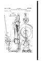
Referring now more particularly to Figure 6, it will be seen that the L-shaped member 70 is used to rigidly hold the tire against vertical movement when the lever 28 is depressed in the operation shown in Figure l. 7 Since th tire will press upright against the extending end of the L-shaped member 10, a frictional engagement between the member and the tube 68 will prevent the raising of the member 76 out of the central aperture in the tube 68.
Th tire tool is equally adaptable to break the bead of small or large tractor tires from the rusted rims by forcing the bead to the drop center of the rim. This operation is best shown in Figure 2. The wheel is placed on base Ii]. Then spoon 44 of the tire engaging member 42 is positioned on the side wall of th tire so that upon depression of the lever 28 the spoon will force the bead of the tire into the drop center of the rim. The wheel is then turned over and th spoon is actuated to break the other bead so that both beads will be in the drop center of the rim. The tire will then be easily removed by hand irons commonly used in tipping one side of the tire over the edge of the rim. The entire wheel, as in Figure 2, may be quite easily rotated to another position for engagement with spoon 44 by rolling engagement on rollers 58. However, as desired, these rollers may be raised out of notches 54 in plates 52. In a like manner, the smaller tires of automobiles may be removed from their drop center rims. I
This tire tool can be readily used in spreading tires apart for ready removal of a tube which is heat bonded or otherwise secured to the inner surface of the tire. As shown best in Figure 4, a clip formed from a pair of substantially S- shaped portions 82 and 84 and a central connecting portion 86 is positioned so as to encompass the tire-engaging member 42 while resting on the spoon 44. The lower portions of the clip form hooks which, when the lever 28 is raised, will pull upon the side wall of th tire. A clamp member generally designated by reference numeral 88 is used to hold a tire-engaging tool 90 rigidly to the base Hi. This tire-engaging tool 90 is provided with a hook portion 92 which will retain the other side wall of the tire in a position against the base I0. Thus, the tire may be easily spread apart. The clamp 88 is of similar design to the clamp used in holding the slide 66 in place. Actually, during the subsequent operations of the device, the original clamp used to hold the slide in place may be moved forward for engagement with the eye 60 instead of the eye 62. The
end of the base In is provided with an aperture 94 through which a lever lock 96 may be secured. The lever lock 96 is provided with a plurality of spaced hooks 98 for selective engagement with the lever 28 so as to hold it in place while applying pressure upon the tire.
Referring now to Figure '7, it will be seen that the jig is formed with an annular integral upper ring I00 which forms an inner shoulder I02 and an outer shoulder I04. The shoulders are provided so as to enable an additional separate ring to be positioned in engagement therewith to add height to the jig 80 if needed.
Since, from the foregoing, the construction and advantages of this tire tool are readily apparent, further description is believed to b unnecessary.
However, since numerous modifications will readily occur to those skilled in the art after a consideration of the foregoing specification and accompanying drawings, it is not intended to limit the invention to the precise embodiment of the tire tool shown and described, but all suitable modifications and equivalents may be resorted to which fall within the scope of the appended claims.
Having described the claimed as new is: Y
1. A tire tool comprising an elongated base, a standard secured to said base at one end thereof, an arm rigidly secured to said standard and extending perpendicularly thereto, a lever pivotally secured to said arm, a tire-engaging member pivotally secured to said lever, a plurality of spaced brackets secured to said base, and a plurality of rollers mounted in said brackets.
2. A tire tool comprising an elongated base, a standard secured to said base at one end thereof, an arm rigidly secured to said standard and ex tending perpendicularly thereto, a lever pivotally secured to said arm, a tire-engaging member pivotally secured to said lever, a plurality of spaced brackets secured to said base, each of said brackets having a notch therein, and a plurality of rollers pivotally mounted in said notches in said brackets.
3. A tire tool comprising an elongated base, a standard secured to said base at one end thereof, an arm rigidly secured to said standard and extending perpendicularly thereto, a lever pivotally secured to said arm, a tire-engaging member pivotally secured to said lever, a plurality of spaced brackets secured to said base, a plurality of rollers mounted in said brackets, and means on said base adapted to hold a tire stationary and a clamp secured to said base adapted to adjustably hold said means on said base.
4. The structure or" claim 3 wherein said clamp comprises a bar, a cylinder secured to one end of said bar, and a pair of hooks each pivotally secured to an end of said cylinder at a point eccentrically dislocated from the center of said cylinder, said hooks engaging eyes secured to said base.
5. A tire tool comprising an elongated base, a standard secured to said base at one end thereof, an arm rigidly secured to said standard and extending perpendicularly thereto, a lever pivotally secured to said arm, a tire-engaging member pivotally secured to said lever, and means on said base adapted to hold a tire stationary, and a clamp secured to said base adapted to adjustably hold said means on said base, said clamp comprising a bar, a cylinder secured to one end of said bar, and a pair of hooks each pivotally secured to an end of said cylinder at a point invention, what is 5 eccentrically dislocated from the center of said cylinder, said hooks engaging eyes secured to said base.
6. The Structure of claim 5 including a plurality of spaced brackets secured to said base. each of said brackets having a notch therein, and a plurality of rollers pivotally mounted in said notches in said brackets.
7. The structure of claim 6 wherein said means comprise a slide horizontally positioned on said base, a tube secured to one end of said slide, and an L-shaped member slidably positioned in said tube, said cylinder being adapted to engage said slide.
8. The structure of claim '7 wherein said lever 15 2,478,214
comprises a pair of spaced members, said arm and said tire-engaging member being pivotally secured to said lever between said spaced members.
VERNER E. HAUTA.
REFERENCES CITED The following references are of record in the file of this patent:
UNITED STATES PATENTS Number Name Date 1,742,590 Freivogel Jan. '7, 1930 2,433,113 qraves Dec. 23, 1947 Turner Aug. 9, 1949
Priority Applications (1)
| Application Number | Priority Date | Filing Date | Title |
|---|---|---|---|
| US125947A US2528362A (en) | 1949-11-07 | 1949-11-07 | Axially shifting type tire removing device |
Applications Claiming Priority (1)
| Application Number | Priority Date | Filing Date | Title |
|---|---|---|---|
| US125947A US2528362A (en) | 1949-11-07 | 1949-11-07 | Axially shifting type tire removing device |
Publications (1)
| Publication Number | Publication Date |
|---|---|
| US2528362A true US2528362A (en) | 1950-10-31 |
Family
ID=22422184
Family Applications (1)
| Application Number | Title | Priority Date | Filing Date |
|---|---|---|---|
| US125947A Expired - Lifetime US2528362A (en) | 1949-11-07 | 1949-11-07 | Axially shifting type tire removing device |
Country Status (1)
| Country | Link |
|---|---|
| US (1) | US2528362A (en) |
Cited By (10)
| Publication number | Priority date | Publication date | Assignee | Title |
|---|---|---|---|---|
| US2642265A (en) * | 1950-07-24 | 1953-06-16 | Cox William Jared | Tire tool |
| US2647722A (en) * | 1950-10-06 | 1953-08-04 | Ernest H Koester | Tire spreader |
| US2691412A (en) * | 1950-12-22 | 1954-10-12 | James P Wood | Jack actuated tire releasing device |
| US2720915A (en) * | 1952-03-25 | 1955-10-18 | Lenoir Marcel | Tire fitting and removing machine |
| US2746528A (en) * | 1953-01-26 | 1956-05-22 | Lee J Damman | Tire remover with a rotatable wheel support |
| US3037549A (en) * | 1960-05-31 | 1962-06-05 | Julian K Jacobson | Tire mounting apparatus |
| FR2617442A1 (en) * | 1987-07-02 | 1989-01-06 | Jungkunz Peter | Device for loosening the beads of a tyre from the rim of a wheel |
| US6752221B1 (en) | 2002-12-19 | 2004-06-22 | Danny Morissette | Self-supporting pneumatic hammer positioner with universal joint |
| US20110073817A1 (en) * | 2009-09-29 | 2011-03-31 | Branik David P | Wheel Ornament Installation Tool |
| US20190030579A1 (en) * | 2017-07-31 | 2019-01-31 | Citic Dicastal Co., Ltd | Wheel pretreatment rack |
Citations (3)
| Publication number | Priority date | Publication date | Assignee | Title |
|---|---|---|---|---|
| US1742590A (en) * | 1927-08-26 | 1930-01-07 | Richard A Jackson | Automobile tire remover |
| US2433113A (en) * | 1944-07-10 | 1947-12-23 | Speedmaster Ltd | Lever actuated tire bead forcing device |
| US2478214A (en) * | 1946-11-06 | 1949-08-09 | Houston G Turner | Axially shifting type tire removing machine |
-
1949
- 1949-11-07 US US125947A patent/US2528362A/en not_active Expired - Lifetime
Patent Citations (3)
| Publication number | Priority date | Publication date | Assignee | Title |
|---|---|---|---|---|
| US1742590A (en) * | 1927-08-26 | 1930-01-07 | Richard A Jackson | Automobile tire remover |
| US2433113A (en) * | 1944-07-10 | 1947-12-23 | Speedmaster Ltd | Lever actuated tire bead forcing device |
| US2478214A (en) * | 1946-11-06 | 1949-08-09 | Houston G Turner | Axially shifting type tire removing machine |
Cited By (11)
| Publication number | Priority date | Publication date | Assignee | Title |
|---|---|---|---|---|
| US2642265A (en) * | 1950-07-24 | 1953-06-16 | Cox William Jared | Tire tool |
| US2647722A (en) * | 1950-10-06 | 1953-08-04 | Ernest H Koester | Tire spreader |
| US2691412A (en) * | 1950-12-22 | 1954-10-12 | James P Wood | Jack actuated tire releasing device |
| US2720915A (en) * | 1952-03-25 | 1955-10-18 | Lenoir Marcel | Tire fitting and removing machine |
| US2746528A (en) * | 1953-01-26 | 1956-05-22 | Lee J Damman | Tire remover with a rotatable wheel support |
| US3037549A (en) * | 1960-05-31 | 1962-06-05 | Julian K Jacobson | Tire mounting apparatus |
| FR2617442A1 (en) * | 1987-07-02 | 1989-01-06 | Jungkunz Peter | Device for loosening the beads of a tyre from the rim of a wheel |
| US6752221B1 (en) | 2002-12-19 | 2004-06-22 | Danny Morissette | Self-supporting pneumatic hammer positioner with universal joint |
| US20110073817A1 (en) * | 2009-09-29 | 2011-03-31 | Branik David P | Wheel Ornament Installation Tool |
| US20190030579A1 (en) * | 2017-07-31 | 2019-01-31 | Citic Dicastal Co., Ltd | Wheel pretreatment rack |
| US10576512B2 (en) * | 2017-07-31 | 2020-03-03 | Citic Dicastal Co., Ltd | Wheel pretreatment rack |
Similar Documents
| Publication | Publication Date | Title |
|---|---|---|
| US2528362A (en) | Axially shifting type tire removing device | |
| US2581086A (en) | Pivotally supported tire bead forcing device | |
| US2695659A (en) | Circumferentially traveling type tire mounting and demounting apparatus | |
| US2406996A (en) | Tire removing apparatus | |
| US1452596A (en) | Tire tool | |
| JPH0333526B2 (en) | ||
| US2948314A (en) | Wheel centering and supporting device | |
| US2488376A (en) | Fluid pressure operated tire and rim assembling and locking ring applying machine | |
| US3247883A (en) | Tire changing tool | |
| US2760563A (en) | Tool and method for loosening tire beads | |
| US3880220A (en) | Tire Bead Loosening Tool | |
| US3517723A (en) | Vehicle tire fitting and removal apparatus | |
| US2684710A (en) | Screw actuated tire bead loosening tool | |
| US2903050A (en) | Circumferentially traveling type tire bead lifting device | |
| US1495884A (en) | Tire tool | |
| US2563987A (en) | Tool for separating the bead of a tire from a rim flange | |
| US3332467A (en) | Bead breaking tool | |
| US3237676A (en) | Tire tool | |
| US3211206A (en) | Adapter for use with tire-changing equipment | |
| US2316023A (en) | Tire removing tool | |
| US2912047A (en) | Circumferentially traveling type tire mounting and demounting device | |
| US3074468A (en) | Device for mounting and dismounting pneumatic tires | |
| US9085204B2 (en) | Attachment for tire mounting machine | |
| US2812788A (en) | Support for circumferentially travelling type tire mounting and demounting apparatus | |
| US2873795A (en) | Device for the removal of tires and king pins |