US2508564A - Air controlled shifting mechanism - Google Patents
Air controlled shifting mechanism Download PDFInfo
- Publication number
- US2508564A US2508564A US764836A US76483647A US2508564A US 2508564 A US2508564 A US 2508564A US 764836 A US764836 A US 764836A US 76483647 A US76483647 A US 76483647A US 2508564 A US2508564 A US 2508564A
- Authority
- US
- United States
- Prior art keywords
- tubular
- shifter
- plug
- rods
- pressure
- Prior art date
- Legal status (The legal status is an assumption and is not a legal conclusion. Google has not performed a legal analysis and makes no representation as to the accuracy of the status listed.)
- Expired - Lifetime
Links
Images

Classifications
-
- F—MECHANICAL ENGINEERING; LIGHTING; HEATING; WEAPONS; BLASTING
- F16—ENGINEERING ELEMENTS AND UNITS; GENERAL MEASURES FOR PRODUCING AND MAINTAINING EFFECTIVE FUNCTIONING OF MACHINES OR INSTALLATIONS; THERMAL INSULATION IN GENERAL
- F16H—GEARING
- F16H63/00—Control outputs from the control unit to change-speed- or reversing-gearings for conveying rotary motion or to other devices than the final output mechanism
- F16H63/02—Final output mechanisms therefor; Actuating means for the final output mechanisms
- F16H63/30—Constructional features of the final output mechanisms
- F16H63/3023—Constructional features of the final output mechanisms the final output mechanisms comprising elements moved by fluid pressure
-
- F—MECHANICAL ENGINEERING; LIGHTING; HEATING; WEAPONS; BLASTING
- F16—ENGINEERING ELEMENTS AND UNITS; GENERAL MEASURES FOR PRODUCING AND MAINTAINING EFFECTIVE FUNCTIONING OF MACHINES OR INSTALLATIONS; THERMAL INSULATION IN GENERAL
- F16H—GEARING
- F16H61/00—Control functions within control units of change-speed- or reversing-gearings for conveying rotary motion ; Control of exclusively fluid gearing, friction gearing, gearings with endless flexible members or other particular types of gearing
- F16H61/26—Generation or transmission of movements for final actuating mechanisms
- F16H61/28—Generation or transmission of movements for final actuating mechanisms with at least one movement of the final actuating mechanism being caused by a non-mechanical force, e.g. power-assisted
- F16H61/30—Hydraulic or pneumatic motors or related fluid control means therefor
- F16H2061/308—Modular hydraulic shift units, i.e. preassembled actuator units for select and shift movements adapted for being mounted on transmission casing
-
- Y—GENERAL TAGGING OF NEW TECHNOLOGICAL DEVELOPMENTS; GENERAL TAGGING OF CROSS-SECTIONAL TECHNOLOGIES SPANNING OVER SEVERAL SECTIONS OF THE IPC; TECHNICAL SUBJECTS COVERED BY FORMER USPC CROSS-REFERENCE ART COLLECTIONS [XRACs] AND DIGESTS
- Y10—TECHNICAL SUBJECTS COVERED BY FORMER USPC
- Y10T—TECHNICAL SUBJECTS COVERED BY FORMER US CLASSIFICATION
- Y10T74/00—Machine element or mechanism
- Y10T74/19—Gearing
- Y10T74/19219—Interchangeably locked
- Y10T74/19377—Slidable keys or clutches
- Y10T74/19414—Single clutch shaft
- Y10T74/19419—Progressive
- Y10T74/19423—Multiple key
- Y10T74/19428—Spur
- Y10T74/19433—Fluid operated
-
- Y—GENERAL TAGGING OF NEW TECHNOLOGICAL DEVELOPMENTS; GENERAL TAGGING OF CROSS-SECTIONAL TECHNOLOGIES SPANNING OVER SEVERAL SECTIONS OF THE IPC; TECHNICAL SUBJECTS COVERED BY FORMER USPC CROSS-REFERENCE ART COLLECTIONS [XRACs] AND DIGESTS
- Y10—TECHNICAL SUBJECTS COVERED BY FORMER USPC
- Y10T—TECHNICAL SUBJECTS COVERED BY FORMER US CLASSIFICATION
- Y10T74/00—Machine element or mechanism
- Y10T74/20—Control lever and linkage systems
- Y10T74/20012—Multiple controlled elements
- Y10T74/20018—Transmission control
- Y10T74/20024—Fluid actuator
Definitions
- Figure 2 is-a -ilongitudinal vertical .sectional view taken along the line 22 ofEigure'l look- ,ing in the direction of .the arrows;
- .the .c1ove1..p1ate3 may be provided with a gasket as .shown at.
- each .guide rod having headportion' '3 by .which it .is held in l T@lationavithlthe.housing member E by cap screws J3 .or 'the'.like. .
- Each 'guide rod also 'is v,provided with an axial v.bore :III and :fa-'fitting :I2 .forra purpose to be later described.
- a ltubular 4shifting member -rI 3 is telescopically arrangedrover the adjacent :ends-:of opposed rods I for Vsliding movement thereon.
- Each tubular member I3 ⁇ is providedwith an.-enlarged yportion I4 ⁇ at each end :thereof'and anenlarged bore l5 in ysaid enlarged portion.
- Each of said .enlarged bores I5 contains a ⁇ packing ⁇ material I6 held therein .by a 'packing ring I1.
- the purpose of the packing -IB is to-effect a seal between 4the tubular members I3 and the .-guiderodfl sufficient to retain the necessary uid pressure within'the tubular 'memben
- the packing I-6 I may .be of any 4conventional orsuitab1e type.
- -Each tubular shiiteremember .'I3 is furtherprovidedwith a partition wall 18 substantially midway ofits length and said partition wall 4is between the opposed endsof vthe aligned-.guide rods .1,.thus.providing a pair -of expansible Apressure .chambers 49 .and 2t withinsaid tubular shifter-member.
- A-compression spring 24 is provided to-effect a seal between 4the tubular members I3 and the .-guiderodfl sufficient to retain the necessary uid pressure within'the tubular 'memben.
- the packing I-6 I may .be of any 4conventional orsuitab1
- each shifter fork . is integral with its tubular shifter -member I3 'but it is to be .understood thatsuch construction is not .necessary for the .practice of this invention since vthe ⁇ shifter :forks .22 may -be constructed separately and attached to the tubular members I3 -in any convenient or 'suitable manner. .
- the shifter -forks 22 engage .movable members in the transmission .mechanism whereby to move said members in -either .direction to .effect a change -in gearratidallasis .wellknownin the art.
- The-cover plate isprovided with a suitable vent or breather. cap 5.24 .whereby the interior'ofV the shifter .mechanism .and .transmission housing is in .communication with the .outer atmosphere.
- a vent is provided to equalize the pressure within the .housing .and .the .outer .atmosphere so that in .the .event .the shifter mechanism .should leak and .allow .iuid under pressure .toenter the transmission. casing, .suchpressure will be dissipated through the vent-.24 to. guard against its .forcing .lubricating oil from the working parts of the transmission mechanism.
- Each of .thettings .l2 is connected,.through a suitahie control valve mechanism ⁇ (not shown) -to a Asnurceof "uid..pressure whereby .fluid under pressure may ,be selectively admitted to the shifter-mechanism.through any one o1 thettingsIZ.
- Each of the aligned guide rods 1 is provided with an enlarged bore 31 adjacent its free end, said bore beingv of sulicient diameter to accommodate the stop nut 33, as clearly shown in the drawings.
- the line A in Figures 3, 4 and 5 represents the mid position of the mechanism and when the mid point of the tubular members I3 lies on line A the controlled gear mechanisms are ln neutral.
- the stop collar 23 thus moving its shifter fork 22 and the associated gear'mechanism to eiect engagement of the selected gears.
- the stop co1- lar 23 thus absorbs any continued thrust due to the fluid pressure in the chamber 20 andprevents such thrust from being transmitted to the rotat- -i ing parts of the gear mechanism, through the fork 22,Y thus preventing undue wear of said parts.
- in theleft-hand chamber will expand to return the shifter member I3, fork 22 and the gear mechanism to neutral position, that is, the position shown in Figure 2.
- adjacent ends of the two tubularshi-fter members I3 are provided with opposedconical recesses 25 and 26. Said recesses are opposite each other when the tubular members I3 are in their mid or neutral position as shown.
- a portion of the housing I is provided with arbore 21 in which a pin 28 is slidably mounted.
- the ⁇ pin 28 is provided with conical ends V29 and 30 and is of such length that when one end is received in one ofthe recesses 25 or 26, its opposite end just clears the side of the other tubular member I3.
- each of the expansible pressure chambers I9 3 Vand 2B 'a plug member 30 ispositioned adjacent the partition wall I8.
- Each of the plug members l 3ll has rigidly attached thereto a guide member l3
- the nuts-33 vare preferably castellated nuts and .are locked in adjusted position by means of cotter pins.
- Vlil'ach of the slide members 32 consists of a cylindrical portion 34 and a flanged portion 35 and a compression spring 36 is located between 3 and reacts against the ilange 35 and the plug 30.
- the tubular member I3 is in such neutral ⁇ position and it is to be noted that the ange members 35 are in abutment with the stop nuts 33 and also engage the ends of the aligned guide rods 1, thus it will be seen that the tubular member I3 is positioned and maintained in such neutral position irrespective of the relative strength of the springs 36 since any excessive force exerted by the stronger of the two springs is absorbed by the stop nut 33 and does not react against the end of the guide rod 1 to move the tubular shifter member I3 from its neutral position.
- , and stop nut 33 (in chamber 20) will yalso move to the left with the member I3, leaving the ange 35 in yabutment with the end of the guide rod 1. Such movement to the left will continue until the stop nut 33 engages the outer face of the ange 35 and renders the spring 36 ineffective to move the parts farther. 'At the same time, the flange 35 in the left-hand chamber I9 will just reach the end of the left-hand guide rod 1 and the shifter mechanism will be in its mid or neutral position.
- FIG. 1 and 3 each show an integral partition wall in the tubular member I3 as dividing the two expansible pressure chambers, it is. to lbe understood that any other suitablemeans could be provided with equal facility.
- the partition wall could be a separate element inserted after the member i3 has been bored.
- the partition wall I8 could be eliminated and the plug members 30 engaging a suitable stop could provide the necessary pressure seal between the chambers.
- the parts 34 and 35 of the slides 32 need not be integral, they could be made as separate elements or the part 34 could be integral with the plug 39.
- a gear shifting mechanism comprising: a support; a pair of axially aligned rods carried by said support and having their adjacent ends axially spaced; a tubular shifter member telescopically slidable over the adjacent ends of said rods; means in said tubular member, between the ends of said rods, providing a fluid pressure seal therein whereby to divide the space between said rod ends into a pair of expansible pressure chambers; a longitudinally slidable member in each of said chambers, stop means to limit the range of sliding movement of each of said slidable members; a compression spring between each slidable member and said sealing means; and means for selectively introducing uid under pressure to either of said chambers.
- a gear shifting mechanism comprising: a support; a pair of axially aligned rods carried by said support and having their adjacent ends axially spaced; a tubular shifter member telescopically slidable over the adjacent ends of said rods; a, partition wall in said tubular member between the ends of said rods and forming, with said rod ends and tubular member, a pair of expansible chambers; a plug in each of said chambers adjacent said partition wall, each said plug supporting an axially extending guide having stop means at its end opposite said plug; a slide on said guide having a portion providing an annular shoulder facing said plug and a portion extending toward said plug to limit the minimum spacing between said plug and said shoulder; a compression spring reacting against said plug and said shoulder and urging said slide into engagement with said stop means and the end of the adjacent rod, the said parts being so proportioned that the distance between the outer ends of said slides, when in engagement with said stops is substantially equal to the distance between the ends of said rods; and means for selectively admitting fluid
- a gear shifting mechanism comprising: a support; a pair of -axially aligned rods carried by said support vand having their adjacent ends axially spaced; a tubular shifter member telescopically slidable over the adjacent ends of said rods; a partition wall in said tubular member between the ends of said rods and forming, with said rod ends and tubular member, a pair of expansible chambers; a, plug in each of said chambers adjacent said partition wall, each said plug supporting an axially extending guide having stop means at its end opposite said plug; a slide on said guide having a portion providing an annular shoulder facing said plug and a portion extending toward said plug to limit the minimum spacing between said plug and said shoulder; a compression spring reacting against said plug and said shoulder and urging said slide into engagement with said stop means and the end of the adjacent rod, the said parts being so proportioned that the distance between the outer ends of said slides, when in engagement with said stops, is substantially equal to the distance between the ends of said rods; a recess
- a gear shifting mechanism comprising: a support; two pairs of axially aligned rods carried by said support and having their adjacent ends axially spaced; a tubular shifter member telescopically slidable over the adjacent ends of each pair of rods; fluid pressure means acting within said tubular members to selectively slide either tubular member in either direction from a mid position; stop means for limiting the movement of each tubular member in each direction; expansible spring means normally urging said tubular members toward said mid position, adjustable stop means to limit the range of action of said spring means and thereby vary said mid position; a conical recess in the external surface of each tubular member, said recesses facing each other when said tubular members are in their mid position; a locking member carried by said support and movable into either recess at the mid position of said tubular members, and means for moving said locking member into the recess in one tubular member when the other tubular member is moved from its mid position whereby to lock said lone tubular member in its mid position until said other tubular
Landscapes
- Engineering & Computer Science (AREA)
- General Engineering & Computer Science (AREA)
- Physics & Mathematics (AREA)
- Fluid Mechanics (AREA)
- Mechanical Engineering (AREA)
- Fluid-Damping Devices (AREA)
Description
H. w. cARDwELl. Erm.
AIR comoLLEn SHIFTING MECHANISM May 23, 195o 2 Sheets-Sheet 1 Filed July 30, 1947 grwam/IDW H. WQCARDWELL ET AL AIR C'ONTROLLED SHIFTING MECHANISM 2 Sheets-Sheet 2 Filed July 30, 1.947
llll Il w m, f uw d .m 4H M 3 A l l! A lll||||llHHH||H n ww. Q/u c. d M y 3 Patented May 23, 1950 iunirreo stares sessel :TENT o FFICE .1 This linventiim re'l'ates to rgear-fshifting mechanismswherein ithe-irati'o ofidrive yrfromva 4source of power to a v4'drivennrenrber dnay Hoe variedl at 'the will offthe operator.
such a gear shifting mechanism that/can befop 'era-ted by a-fl`uid=under pressure, preferablyair, from` arremotercohtrol station. l
. Itis va further Yobject fof 'this `invention 'to provide 'a :gear *shifting mechanism `that -is .simple and economical --fconstruction -and providing vfor-irnaximum efciency and-dependability in operation.
'Itis a* further -robject iof this invention v.to profvide such ia zgear shifting @mechanism that may bel-readily `attached to r'a-standard selective Agear dri-ve ytofreplaee fthe iconventional .manual lo yother'shiftinganechanism.
A*It .is-vastill further yobject of this .invention to :provide such-.agear-shifting .mechanism wherein the fluid nnnder pressure will actuate Ameans to Veffect -theidesired v.gear `ratio and wherein ccntinued- Yapplication vof. .the .fluid ...pressure .will not cause: undue -wearsof the `oper-ated parts.
In `the :accompanying drawings .there are iillnstrated -,preferred -..embodiments .of -this invention,
and .in which:
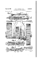
Figure `1 .is .a top ,plan `view .of one .embodiment of the .gear nshifting :mechanism .with .the `cover .plateiremovem Y Figure 2 is-a -ilongitudinal vertical .sectional view taken along the line 22 ofEigure'l look- ,ing in the direction of .the arrows;
Figure' .is `a vertical sectional Iview similar to Figure Zhut illustrating-a modified embodiment;
desired, .the .c1ove1..p1ate3 .may be provided with a gasket as .shown at.
lhe housing .i is provided at .opposite -ends .with .opposed .pairs *ofl openings In .the pposed openings of each pair, .a .pairpf axially .aligned .guidefrods .l .are mounted, each .guide rod having headportion' '3 by .which it .is held in l T@lationavithlthe.housing member E by cap screws J3 .or 'the'.like. .The .adjacent ends IU ,oithealignedguiderodsareaxiallyspacedapart falsubstantial distance .as .clearly shownfinFi'g- -2 ure '2. Each 'guide rod also 'is v,provided with an axial v.bore :III and :fa-'fitting :I2 .forra purpose to be later described.
A ltubular 4shifting member -rI 3 is telescopically arrangedrover the adjacent :ends-:of opposed rods I for Vsliding movement thereon. :Each tubular member I3 `is providedwith an.-enlarged yportion I4 `at each end :thereof'and anenlarged bore l5 in ysaid enlarged portion. Each of said .enlarged bores I5 contains a `packing `material I6 held therein .by a 'packing ring I1. .The purpose of the packing -IB is to-effect a seal between 4the tubular members I3 and the .-guiderodfl sufficient to retain the necessary uid pressure within'the tubular 'memben The packing I-6 Imay .be of any 4conventional orsuitab1e type. -Each tubular shiiteremember .'I3 is furtherprovidedwith a partition wall 18 substantially midway ofits length and said partition wall 4is between the opposed endsof vthe aligned-.guide rods .1,.thus.providing a pair -of expansible Apressure .chambers 49 .and 2t withinsaid tubular shifter-member. A-compression spring 24. .is .located in Ieach pressure chamber 'and 'each .abuts .at one .end -against .the end of one ofthe guide 4rods landat its .other end.againstthe-.partition wall 18. Each tubular shifter member .I3 `is .turther .provided with a shifter fork.22. Asishown, each shifter fork .is integral with its tubular shifter -member I3 'but it is to be .understood thatsuch construction is not .necessary for the .practice of this invention since vthe `shifter :forks .22 may -be constructed separately and attached to the tubular members I3 -in any convenient or 'suitable manner. .The shifter -forks 22 engage .movable members in the transmission .mechanism whereby to move said members in -either .direction to .effect a change -in gearratidallasis .wellknownin the art.
vEach .of the aligned guide .rods .1 is Vfurther `provided .withastop collar .-.23 between the ends of the tubular shifter member and the housing member I.
The-cover plateisprovided with a suitable vent or breather. cap 5.24 .whereby the interior'ofV the shifter .mechanism .and .transmission housing is in .communication with the .outer atmosphere. Such a vent is provided to equalize the pressure within the .housing .and .the .outer .atmosphere so that in .the .event .the shifter mechanism .should leak and .allow .iuid under pressure .toenter the transmission. casing, .suchpressure will be dissipated through the vent-.24 to. guard against its .forcing .lubricating oil from the working parts of the transmission mechanism.
Each of .thettings .l2 is connected,.through a suitahie control valve mechanism `(not shown) -to a Asnurceof "uid..pressure whereby .fluid under pressure may ,be selectively admitted to the shifter-mechanism.through any one o1 thettingsIZ.
4 Each of the aligned guide rods 1 is provided with an enlarged bore 31 adjacent its free end, said bore beingv of sulicient diameter to accommodate the stop nut 33, as clearly shown in the drawings. The line A in Figures 3, 4 and 5 represents the mid position of the mechanism and when the mid point of the tubular members I3 lies on line A the controlled gear mechanisms are ln neutral.
by the stop collar 23, thus moving its shifter fork 22 and the associated gear'mechanism to eiect engagement of the selected gears. The stop co1- lar 23 thus absorbs any continued thrust due to the fluid pressure in the chamber 20 andprevents such thrust from being transmitted to the rotat- -i ing parts of the gear mechanism, through the fork 22,Y thus preventing undue wear of said parts. Upon release of the pressure from the chamber 2Q thespring 2| in theleft-hand chamber will expand to return the shifter member I3, fork 22 and the gear mechanism to neutral position, that is, the position shown in Figure 2. In the embodiment just described it is necessary that the springs 2| Vbe of equal strength since the neutral position of the shifter member I3 is that position at which the forces of the opposed springs just balance each other. The springs must be so balancedthat the gear mechanismv controlled thereby is heldV normally in its neutral or disengaged position. Y i
As shown in Figure 1, adjacent ends of the two tubularshi-fter members I3 are provided with opposedconical recesses 25 and 26. Said recesses are opposite each other when the tubular members I3 are in their mid or neutral position as shown. A portion of the housing I is provided with arbore 21 in which a pin 28 is slidably mounted. The `pin 28 is provided with conical ends V29 and 30 and is of such length that when one end is received in one ofthe recesses 25 or 26, its opposite end just clears the side of the other tubular member I3. Y Thus, if the tubular member I3 shown at the top of Figure 1 were shifted either to the right or left, the conical sides of the recess 26 would force the lpin 2B downwardly and into the recess.25 thuslocking the lower tubular member I3 in its neutral position until such time y described. This embodiment differs from that in l Figures 1 and 2in that means are provided for positivelydetermining the neutral or mid position ofctheqtubular shifter members I3 irrespec- ,tive of `therelative Vstrength ofthe springs employed.
In 4each of the expansible pressure chambers I9 3 Vand 2B 'a plug member 30 ispositioned adjacent the partition wall I8. Each of the plug members l 3ll has rigidly attached thereto a guide member l3|fon which a slide 32 is mounted for sliding u s movement into engagementrwith a stop nut 33 threaded on the free end of each of the guides 3|.
The nuts-33 vare preferably castellated nuts and .are locked in adjusted position by means of cotter pins. Vlil'ach of the slide members 32 consists of a cylindrical portion 34 and a flanged portion 35 and a compression spring 36 is located between 3 and reacts against the ilange 35 and the plug 30.
As shown in Figure 3, the tubular member I3 is in such neutral `position and it is to be noted that the ange members 35 are in abutment with the stop nuts 33 and also engage the ends of the aligned guide rods 1, thus it will be seen that the tubular member I3 is positioned and maintained in such neutral position irrespective of the relative strength of the springs 36 since any excessive force exerted by the stronger of the two springs is absorbed by the stop nut 33 and does not react against the end of the guide rod 1 to move the tubular shifter member I3 from its neutral position.
If iiuid under pressure is admitted to one of the expansible chambers, for instance, the left hand chamber I 9, that chamber will be expanded and the tubular shifter member I3 will be moved to the right and the parts will assume the position shown in Figure 4. It will be noted from Figure 4 that when pressure is admitted to the leftr hand chamber I9 the spring in the right hand chamber will be compressed until the end 38 of the cylindrical portion 34 engages the plug 30 and since the ange 35 is in engagement with the end of the right`hand guide rod 1, the shifter mechanism cannot move any lfurther toward the right. Thus, a positive stop is provided to limit the movement of the fork 22 and its controlled gearV mechanism. The parts are so proportioned that the controlled gear member will be moved a suilicient amount to properly engage with its associated transmission element but will not be urged beyond that point. During movement of the parts toward the right as shown in Figure 4, the spring and stop mechanism located in the left-hand cham-ber I9 will vbe ineffective and merely move with the shifter member I3 to the right away from the adjacent end of the lefthand guide rod 1. *Y l Upon release of the uid vpressure from the chamber I97 the lcompressed spring 36 in the chamber 2i) will move the tubular shifter member I3, its fork 22, and the controlled gear part to the left. The plug member 3|), guide 3|, and stop nut 33 (in chamber 20) will yalso move to the left with the member I3, leaving the ange 35 in yabutment with the end of the guide rod 1. Such movement to the left will continue until the stop nut 33 engages the outer face of the ange 35 and renders the spring 36 ineffective to move the parts farther. 'At the same time, the flange 35 in the left-hand chamber I9 will just reach the end of the left-hand guide rod 1 and the shifter mechanism will be in its mid or neutral position.
When the fluid under pressure is admitted to the right-hand chamber 2D, the parts will as,- sume the position shown in Figure 5 with the spring and stop elements in the left-hand chamber functioning exactly as did those in the righthand chamber when the uid under pressure was admitted to the chamber I9.
Although the embodiments of Figures 1 and 3 each show an integral partition wall in the tubular member I3 as dividing the two expansible pressure chambers, it is. to lbe understood that any other suitablemeans could be provided with equal facility. For instance, the partition wall could be a separate element inserted after the member i3 has been bored. Furthermore, in the embodiment of Figures 3 to 5 the partition wall I8 could be eliminated and the plug members 30 engaging a suitable stop could provide the necessary pressure seal between the chambers. Likewise the parts 34 and 35 of the slides 32 need not be integral, they could be made as separate elements or the part 34 could be integral with the plug 39.
Although the preferred actuating uid for the gear shifting mechanism of this invention is com pressed air, clearly any other suitable pressure transmitting iiuid could be employed with equal facility and it is not intended that this invention be limited to the use of compressed air.
While two specic embodiments of the invention have been described, they are intended to be merely illustrative and not to limit the scope of the invention. It is contemplated that all embodiments falling within the scope of the appended claims be considered as included in the present invention.
We claim:
1. A gear shifting mechanism comprising: a support; a pair of axially aligned rods carried by said support and having their adjacent ends axially spaced; a tubular shifter member telescopically slidable over the adjacent ends of said rods; means in said tubular member, between the ends of said rods, providing a fluid pressure seal therein whereby to divide the space between said rod ends into a pair of expansible pressure chambers; a longitudinally slidable member in each of said chambers, stop means to limit the range of sliding movement of each of said slidable members; a compression spring between each slidable member and said sealing means; and means for selectively introducing uid under pressure to either of said chambers.
2. A gear shifting mechanism comprising: a support; a pair of axially aligned rods carried by said support and having their adjacent ends axially spaced; a tubular shifter member telescopically slidable over the adjacent ends of said rods; a, partition wall in said tubular member between the ends of said rods and forming, with said rod ends and tubular member, a pair of expansible chambers; a plug in each of said chambers adjacent said partition wall, each said plug supporting an axially extending guide having stop means at its end opposite said plug; a slide on said guide having a portion providing an annular shoulder facing said plug and a portion extending toward said plug to limit the minimum spacing between said plug and said shoulder; a compression spring reacting against said plug and said shoulder and urging said slide into engagement with said stop means and the end of the adjacent rod, the said parts being so proportioned that the distance between the outer ends of said slides, when in engagement with said stops is substantially equal to the distance between the ends of said rods; and means for selectively admitting fluid under pressure to either oi said chambers.
3. A gear shifting mechanism comprising: a support; a pair of -axially aligned rods carried by said support vand having their adjacent ends axially spaced; a tubular shifter member telescopically slidable over the adjacent ends of said rods; a partition wall in said tubular member between the ends of said rods and forming, with said rod ends and tubular member, a pair of expansible chambers; a, plug in each of said chambers adjacent said partition wall, each said plug supporting an axially extending guide having stop means at its end opposite said plug; a slide on said guide having a portion providing an annular shoulder facing said plug and a portion extending toward said plug to limit the minimum spacing between said plug and said shoulder; a compression spring reacting against said plug and said shoulder and urging said slide into engagement with said stop means and the end of the adjacent rod, the said parts being so proportioned that the distance between the outer ends of said slides, when in engagement with said stops, is substantially equal to the distance between the ends of said rods; a recess in the end of each of said rods to accommodate said stop means when said slides are in engagement with said rod ends; and axial bores in said rods, communicating with said recesses and a source of uid pressure whereby iiuid under pressure may be selectively admitted to either of said chambers to effect sliding movement of said tubular shifter member in one direction.
4. A gear shifting mechanism comprising: a support; two pairs of axially aligned rods carried by said support and having their adjacent ends axially spaced; a tubular shifter member telescopically slidable over the adjacent ends of each pair of rods; fluid pressure means acting within said tubular members to selectively slide either tubular member in either direction from a mid position; stop means for limiting the movement of each tubular member in each direction; expansible spring means normally urging said tubular members toward said mid position, adjustable stop means to limit the range of action of said spring means and thereby vary said mid position; a conical recess in the external surface of each tubular member, said recesses facing each other when said tubular members are in their mid position; a locking member carried by said support and movable into either recess at the mid position of said tubular members, and means for moving said locking member into the recess in one tubular member when the other tubular member is moved from its mid position whereby to lock said lone tubular member in its mid position until said other tubular member returns to its mid position.
HARLAND W. CARDWELL. JAMES W. HAUPT.
REFERENCES CITED The following references are of record in the file of this patent:
UNT..| ED STATES PATENTS Number Name Date 68,994 King Sept. 17, 1867 859,737 Brown July 9, 1907 1,010,054 Irish Nov. 28, 1911 1,141,589 Taylor June 1, 1915 2,110,994 Linsley Mar. 15, 1938 2,242,542 Peterson May 20, 1941 2,403,328 Banning July 2, 194B FOREIGN PATENTS Number Country Date 1,193 Great Britain 1868 800,878 France July 21, 1936
Priority Applications (1)
| Application Number | Priority Date | Filing Date | Title |
|---|---|---|---|
| US764836A US2508564A (en) | 1947-07-30 | 1947-07-30 | Air controlled shifting mechanism |
Applications Claiming Priority (1)
| Application Number | Priority Date | Filing Date | Title |
|---|---|---|---|
| US764836A US2508564A (en) | 1947-07-30 | 1947-07-30 | Air controlled shifting mechanism |
Publications (1)
| Publication Number | Publication Date |
|---|---|
| US2508564A true US2508564A (en) | 1950-05-23 |
Family
ID=25071932
Family Applications (1)
| Application Number | Title | Priority Date | Filing Date |
|---|---|---|---|
| US764836A Expired - Lifetime US2508564A (en) | 1947-07-30 | 1947-07-30 | Air controlled shifting mechanism |
Country Status (1)
| Country | Link |
|---|---|
| US (1) | US2508564A (en) |
Cited By (14)
| Publication number | Priority date | Publication date | Assignee | Title |
|---|---|---|---|---|
| US2656062A (en) * | 1950-03-28 | 1953-10-20 | Julian B Thomas | Pallet gripping device |
| US2826923A (en) * | 1949-07-05 | 1958-03-18 | Joy Mfg Co | Head swinging mechanism for a continuous miner |
| US4003219A (en) * | 1975-04-21 | 1977-01-18 | United States Steel Corporation | Hydraulically operated retractable spindle |
| US4341423A (en) * | 1980-12-22 | 1982-07-27 | International Harvester Co. | Basket lift apparatus |
| US4449416A (en) * | 1981-09-04 | 1984-05-22 | J. I. Case Company | Transmission control system |
| US4793458A (en) * | 1987-11-09 | 1988-12-27 | Dana Corporation | Shift motor assembly for a two-speed axle |
| US5878624A (en) * | 1997-06-06 | 1999-03-09 | Borg-Warner Automotive, Inc. | Single rail shift operator assembly |
| WO1999032808A1 (en) * | 1997-12-19 | 1999-07-01 | Zf Friedrichshafen Ag | Gear shifting unit |
| FR2798978A1 (en) * | 1999-09-28 | 2001-03-30 | Renault | PASSAGE FORK ASSEMBLY FOR ROBOTIC GEARBOX, AND PASSAGE DEVICE INTEGRATING THIS ASSEMBLY |
| DE102007035291A1 (en) | 2007-07-27 | 2009-01-29 | Schaeffler Kg | Device for actuating a switching element |
| DE102008004497A1 (en) | 2008-01-16 | 2009-07-23 | Schaeffler Kg | Shifting device for gear change transmission, has rod guided through chamber in pressure-tight manner and surface provided in chamber, where surface stays in effective connection with rod and subjectable with medium in sealed manner |
| WO2010031555A1 (en) * | 2008-09-18 | 2010-03-25 | Daimler Ag | Transmission unit |
| DE202011052246U1 (en) | 2010-12-23 | 2012-01-16 | Getrag Ford Transmissions Gmbh | Manual transmission with housing and shift fork |
| CN114857263A (en) * | 2022-05-30 | 2022-08-05 | 湖北中航精机科技有限公司 | Transmission, shift fork structure and assembly method thereof |
Citations (8)
| Publication number | Priority date | Publication date | Assignee | Title |
|---|---|---|---|---|
| US68994A (en) * | 1867-09-17 | woodward | ||
| US859737A (en) * | 1906-09-29 | 1907-07-09 | David George Brown | Telemotor apparatus. |
| US1010054A (en) * | 1910-12-15 | 1911-11-28 | Allen M Irish | Gear-changing device. |
| US1141589A (en) * | 1912-10-26 | 1915-06-01 | Taylor Automatic Air Control Company | Fluid-pressure automobile control mechanism. |
| FR800878A (en) * | 1935-04-20 | 1936-07-21 | Remote control mechanism, pneumatic or electro-pneumatic, for gear changes and for reversers, in particular for railcars | |
| US2110994A (en) * | 1936-04-03 | 1938-03-15 | Vaco Products Inc | Automotive vehicle |
| US2242542A (en) * | 1938-10-05 | 1941-05-20 | Spicer Mfg Corp | Hydraulic gear shifting mechanism |
| US2403328A (en) * | 1943-05-14 | 1946-07-02 | A C Wickman Ltd | Hydraulic mechanism |
-
1947
- 1947-07-30 US US764836A patent/US2508564A/en not_active Expired - Lifetime
Patent Citations (8)
| Publication number | Priority date | Publication date | Assignee | Title |
|---|---|---|---|---|
| US68994A (en) * | 1867-09-17 | woodward | ||
| US859737A (en) * | 1906-09-29 | 1907-07-09 | David George Brown | Telemotor apparatus. |
| US1010054A (en) * | 1910-12-15 | 1911-11-28 | Allen M Irish | Gear-changing device. |
| US1141589A (en) * | 1912-10-26 | 1915-06-01 | Taylor Automatic Air Control Company | Fluid-pressure automobile control mechanism. |
| FR800878A (en) * | 1935-04-20 | 1936-07-21 | Remote control mechanism, pneumatic or electro-pneumatic, for gear changes and for reversers, in particular for railcars | |
| US2110994A (en) * | 1936-04-03 | 1938-03-15 | Vaco Products Inc | Automotive vehicle |
| US2242542A (en) * | 1938-10-05 | 1941-05-20 | Spicer Mfg Corp | Hydraulic gear shifting mechanism |
| US2403328A (en) * | 1943-05-14 | 1946-07-02 | A C Wickman Ltd | Hydraulic mechanism |
Cited By (20)
| Publication number | Priority date | Publication date | Assignee | Title |
|---|---|---|---|---|
| US2826923A (en) * | 1949-07-05 | 1958-03-18 | Joy Mfg Co | Head swinging mechanism for a continuous miner |
| US2656062A (en) * | 1950-03-28 | 1953-10-20 | Julian B Thomas | Pallet gripping device |
| US4003219A (en) * | 1975-04-21 | 1977-01-18 | United States Steel Corporation | Hydraulically operated retractable spindle |
| US4341423A (en) * | 1980-12-22 | 1982-07-27 | International Harvester Co. | Basket lift apparatus |
| US4449416A (en) * | 1981-09-04 | 1984-05-22 | J. I. Case Company | Transmission control system |
| US4793458A (en) * | 1987-11-09 | 1988-12-27 | Dana Corporation | Shift motor assembly for a two-speed axle |
| US5878624A (en) * | 1997-06-06 | 1999-03-09 | Borg-Warner Automotive, Inc. | Single rail shift operator assembly |
| WO1999032808A1 (en) * | 1997-12-19 | 1999-07-01 | Zf Friedrichshafen Ag | Gear shifting unit |
| FR2798978A1 (en) * | 1999-09-28 | 2001-03-30 | Renault | PASSAGE FORK ASSEMBLY FOR ROBOTIC GEARBOX, AND PASSAGE DEVICE INTEGRATING THIS ASSEMBLY |
| WO2001023785A1 (en) * | 1999-09-28 | 2001-04-05 | Renault | Gearshift device for robotic gearbox |
| DE102007035291A1 (en) | 2007-07-27 | 2009-01-29 | Schaeffler Kg | Device for actuating a switching element |
| DE102007035291B4 (en) | 2007-07-27 | 2021-12-16 | Schaeffler Technologies AG & Co. KG | Device for the hydraulic or pneumatic actuation of a switching element |
| DE102008004497A1 (en) | 2008-01-16 | 2009-07-23 | Schaeffler Kg | Shifting device for gear change transmission, has rod guided through chamber in pressure-tight manner and surface provided in chamber, where surface stays in effective connection with rod and subjectable with medium in sealed manner |
| WO2010031555A1 (en) * | 2008-09-18 | 2010-03-25 | Daimler Ag | Transmission unit |
| DE202011052246U1 (en) | 2010-12-23 | 2012-01-16 | Getrag Ford Transmissions Gmbh | Manual transmission with housing and shift fork |
| DE102010056101A1 (en) | 2010-12-23 | 2012-06-28 | Getrag Ford Transmissions Gmbh | Gearbox for motor vehicle, has stationary pins plugged into tubular ends of shift fork and integrally provided in housing portions abutted together by forming common casing line which is enclosed by flange portion |
| CN102606729A (en) * | 2010-12-23 | 2012-07-25 | 格特拉克·福特传动系统有限公司 | Gearbox for motor vehicle |
| DE102010056101B4 (en) * | 2010-12-23 | 2012-09-27 | Getrag Ford Transmissions Gmbh | Manual transmission with housing and shift fork |
| CN102606729B (en) * | 2010-12-23 | 2015-09-23 | 格特拉克·福特传动系统有限公司 | There is the manual transmission of housing and selector fork |
| CN114857263A (en) * | 2022-05-30 | 2022-08-05 | 湖北中航精机科技有限公司 | Transmission, shift fork structure and assembly method thereof |
Similar Documents
| Publication | Publication Date | Title |
|---|---|---|
| US2508564A (en) | Air controlled shifting mechanism | |
| US2163982A (en) | Fluid-operated jack | |
| US2356598A (en) | Operating mechanism for clutches | |
| US2476376A (en) | Screw jack with a reversible motor and safety ejection means | |
| US2848014A (en) | Detent mechanism for hydraulic control valves | |
| US2811136A (en) | Lock mechanism for fluid motors | |
| US3247768A (en) | Interlock for hydraulic control valves and the like | |
| US2674469A (en) | Fluid coupling | |
| US2434828A (en) | Piston locking means for fluid actuated jacks | |
| US2217880A (en) | Unloading relief valve | |
| US3026850A (en) | Fail-safe control for fluid pressure actuators | |
| US3237641A (en) | Preselective command device | |
| US2282591A (en) | Transmission | |
| US3790125A (en) | Control valve with power accumulating, snap action, spool drive | |
| US3071930A (en) | Hydraulic differential force transmission means | |
| US2575982A (en) | Fluid pressure control mechanism | |
| US2436947A (en) | Overload release clutch | |
| US4392556A (en) | Actuator locking device | |
| US2753025A (en) | Mechanism for the releasing of the clutch and the changing of gears in automobile transmissions | |
| US2255359A (en) | Compressor | |
| US2701629A (en) | Shock absorber | |
| US2402842A (en) | Locking device | |
| US2403328A (en) | Hydraulic mechanism | |
| US2762230A (en) | Reversible transmission | |
| US2189679A (en) | Gear shifting mechanism |