US2502012A - Apparatus and method for continuous manufacture of seamed tubing - Google Patents
Apparatus and method for continuous manufacture of seamed tubing Download PDFInfo
- Publication number
- US2502012A US2502012A US750566A US75056647A US2502012A US 2502012 A US2502012 A US 2502012A US 750566 A US750566 A US 750566A US 75056647 A US75056647 A US 75056647A US 2502012 A US2502012 A US 2502012A
- Authority
- US
- United States
- Prior art keywords
- mandrel
- rolls
- pipe
- tubing
- strips
- Prior art date
- Legal status (The legal status is an assumption and is not a legal conclusion. Google has not performed a legal analysis and makes no representation as to the accuracy of the status listed.)
- Expired - Lifetime
Links
Images


Classifications
-
- B—PERFORMING OPERATIONS; TRANSPORTING
- B21—MECHANICAL METAL-WORKING WITHOUT ESSENTIALLY REMOVING MATERIAL; PUNCHING METAL
- B21C—MANUFACTURE OF METAL SHEETS, WIRE, RODS, TUBES, PROFILES OR LIKE SEMI-MANUFACTURED PRODUCTS OTHERWISE THAN BY ROLLING; AUXILIARY OPERATIONS USED IN CONNECTION WITH METAL-WORKING WITHOUT ESSENTIALLY REMOVING MATERIAL
- B21C37/00—Manufacture of metal sheets, rods, wire, tubes, profiles or like semi-manufactured products, not otherwise provided for; Manufacture of tubes of special shape
- B21C37/06—Manufacture of metal sheets, rods, wire, tubes, profiles or like semi-manufactured products, not otherwise provided for; Manufacture of tubes of special shape of tubes or metal hoses; Combined procedures for making tubes, e.g. for making multi-wall tubes
- B21C37/08—Making tubes with welded or soldered seams
Definitions
- This invention relates to an apparatus and a method for continuous manufacture of seam welded tubing, particularly from rolls of relatively thin, strip-sheet stock.
- the present application is a continuation-in-part of an earlier application, Serial Number 563,969, filed November 17, 1944, which is now abandoned.
- the present invention was born following a fruitless search for years for a single machine which would, make thin walled welded tubing in a variety of sizes.
- the invention described in the present application makes it possible on a single machine to make continuous welded tubing of very thin walled material (0.025" to 0.050") in a great range of diameters (3" to 12" and greater) with out any forming rolls, merely by changing the mandrel and adjusting the other parts,
- very thin walled material 0.025" to 0.050
- diameters 3" to 12" and greater
- the method of this invention includes the steps 0 (1) Bringing together two continuous strips of flat stock over a mandrel,
- Another achievement of the invention is to provide machinery by which welded seamed tubing can be manufactured economically continuously automatically or semi-automatically, and can be cut to any desired length after being otherwise completed.
- the tubing or pipe of the kind here contemplated, among other things, is used extensively for portable irrigation pipe.
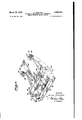
- I Fig. i is a .view in side elevation of the frontportion of a device embodying the principles of this inventiomthe device is shown somewhat in broken in the middle and somewhat foreshort-' ened so that it can be shown in large size on one sheet; at several points below the mandrel are cross-sectional views Figs. 2a to 2h of the mandrel, each showing its shape and the shape of the pipe at the point of the cross-section;'
- Fig. 3 is a back view in side elevation of the after part of the device not shown in Fig. 1, and includes the pipe cut-off unit; in this view the made pipe is moving to the left, whereas Figs. 1 and 2 are front side views, and the pipe is moving to the right; the cut-off saw is shown in solid lines at the beginning of its travel and in dotted lines at the end of it travel;
- Fig. 4 is a view in elevation taken along the line IV-IV in Fig. 1. looking from the right to the left, showing the part Of the machine where the strips of material are first closed together at their edges around the mandrel;
- Fig. 5 is a view in side elevation and section along the line V--V in Fig. 4;
- Fig. 6 is a view in perspective of the mandrel anchor and rollers shown in Figs. 4 and 5;
- Fig. 'l is a view in front elevation of the seaming station, looking from the left of Fig. 1 along the line IV--IV;
- Fig. 8 is a view looking from the left in Fig. 1 along the line VIII-VIII. showing one set of driving rolls;
- Fig. 9 is a view taken along the line IX-IX in Fig. 8.
- Fig. 10 is a view taken along the line X-X of Fig. 1, showing the trimming rolls;
- Fig. 11 is a. view taken along the line XI-XI of Fig. 10;
- Fig. 12 is a view in section taken along the line XIIXII in Fig. 1, showing a pair of the rollers which curl the seams in against the pipe;
- Fig. 13 is a view of Fig. 1 in the vicinity of the line XII-XII looking from the side at two of the curling rollers;
- Fig. 14 is a plan view looking down on Fig. 13;
- Fig. 15 is a view taken along the line XVXV of Fig. 1, showing a steady rest;
- Fig. 16 is a view in elevation looking at the steady rest from the side;
- Fig. 17 is a view in side elevation of the cut-off saw showing it in its end position when it has cut through the tubing;
- Fig. 18 is a front view of the cut-off saw upon completion of a cut.
- Fig. 19 is a diagrammatic view of the electriceye and relay systems operating the cut-off saw.
- the machine here described is designed for continuous and automatic manufacture of twinseamed tubing of any desired length or lengths.
- Two fiat strips are brought into position on opposite sides of a substantially flat mandrel from two rolls of strip stock. They are welded at each side while the two strips are still substantially flat and are passing over the mandrel.
- mandrel is tapered from a flat strip to a cylinder, and imparts this cylindrical shape to the welded strips as they are impelled along the mandrel.
- the welded impelling seams are then trimmed, if desired, and can be curled and bent in against the side of the pipe.
- the cylindrical section of the mandrel is enlarged so that the pipe is stretched beyond its elastic limit as it nears the cut-off station to give the pipe further rigidity as well as to remove any tendency for it to twist. The process is completed when the desired length of pipe is cut from the continuously forming tube.
- the mandrel 20 begins as a flat strip 22, shown in section in Fig 20 below Fig. 2.
- the mandrel 20 must be capable of enduring a considerable stretching force acting over its whole length and must be firmly anchored at this end. especially since it is preferable not to anchor the opposite end of the mandrel 20.
- One end of each of two plates 24 and 25 are welded or bolted securely to the flat mandrel strip 22, and an anchor block 23 is welded or bolted between the opposite ends of the plates 24 and 25. (See Fig. 6.)
- the anchor plate 23 is passed through the slot 21 between the plates 24 and 25, and is rigidly fixed at each end to the brackets 3
- the length of the slot 21 is substantially greater than the width of the anchor plate 28, and there is enough clearance between the plate 28 and the plates 24 and 25 so that it will move back and forth between them freely.
- the anchor block 26 is pulled against the anchor plate 23, but whenever the machine is to be stopped, the seam welder halts the welding just before the pipe stops moving. To avoid waste of material, the sheet stock must be backed up in the machine before it is started again.
- the slack space in the slot 2! permits the whole mandrel 20 to be backed up at this time, so the welding can be resumed where it left off. Additional movement fore and aft of the mandrel may be obtained by loosening the nuts 33 on the bolts 33 which hold the anchor plate to the brackets 3
- the anchor plate 28 is unbolted and removed from the slot 21. After the mandrel has been replaced and the distance between the brackets 3
- the rollers 34 are mounted for free rotation on stub shafts 35 which are journaled into the brackets 3
- stub shafts 35 At the bottom of each of the brackets 3
- the thread 40 At one end of the axle the thread 40 is left-hand, and at the other end of the axle 38 the thread 4
- Similar adjustable apparatus in other pertinent parts of the machine, enables the manufacture of several different sizes of pipe in the same machine merely by substituting a different size mandrel and a few dependent parts and then adjusting the other parts of the machine to the new size. The changeover can be made within a relatively short period of time.
- a pair of guide rollers 40 are used, each having a grooved guide slot 40. Additional rollers 45 may be mounted on the machine before and after the seaming operation to guide the strips or seamed envelope and prevent damage to it.
- Such a set are shown mounted on the stub shafts 41, which are attached to the main frame 30.
- the preferable method of seaming the strips together is that of seam welding.
- Two standard continuous seam welding machines 00 and I may be used. It is preferable that they be of the type that can be adjusted by machinery inside thecabinet (not illustrated) to give a range of different seams and speeds.
- the main frames 00 and II of the seam welders are preferably mounted on wheels 53 which roll on rails 04 transverse to the main frame 30 and preferably have a means to lock them at any desired position along therails. Weldersof this type are easily adjusted to accommodate many different pipe sizes. It is also preferable that the pipe be cooled by a steady stream of water to dissipate as soon as possible the heat from the welding operation.
- the welding machine 50 has the two disc electrodes 85 and 50, and the machine 5
- Each of the wheels 55, '56, 01, and 50 is mounted for free rotation onstub shafts 59 and none is intended to drive the strips I2 and I1.
- current passes between each pair of electrodes and spot welds .a small area of the strips I2 and I3 together. interval is adjusted in relation to the speed at which the strips pass over the welding wheels 55, 56, 51, and 50 so that the spot areas join to form ,a continuous seam GI on each side of the substantially flat envelope 60.
- the net result of the welding operation is thus to Join the two strips I2 and I 3 at that point into a seamed tubular envelope 60 around the substantially flat mandrel section 22.
- pairs of lateral guide rolls 45 in front of these feed rolls I0 and in front of at least the first of the several pairs of feed rolls 1 I.
- the feed rolls I0 and 'II are preferably of identical design and comprise the entire driving mecha- The period of this
- the main machine frame 00 supports the driving falls 10 and 1
- each carriage 14 and I! is a collar I0, similar to the collar I1 and similarly slidable along over the opositely threaded ends of the axle I3.
- the geared sprocket wheels 11 are synchroniaed by a continuous chain drive It and are provided with identical reduction gear systems 00 which drive the axles 0
- the knurled wheels 03 and 04 dig into the seamed edges 0i and propel the tube I00 along the mandrel. Considerable power and a high degree of traction is necessary, and the construction must be rugged throughout.
- the hydraulic cylinders 85 maintain and equalize the pressure of'the knurled wheels 00 and 84 on the seams 0
- the driving means is preferably made reversible so that the tube I00 and the mandrel 20 may be backed up before starting the machine after it has been stopped, for the reason already tion 94.
- the tube I00 is formed from the substantially flat envelope 60 (see Fig. 2b) by propelling it along the mandrel 20. No special forming machinery or expensive shaping rolls are needed, for the tube conforms itself to the shape of the mandrel 20. Between the feed rolls I0 and the feed rolls 'l I, over the section93, shown in Fig. 2, the mandrel 20 changes smoothly from a flat strip 22'to a flat elliptical section 90, to a rounder elliptical section 0
- the mandrel 20 may bemade in several sections which can be welded or threaded together.
- the enlarged or stretching section 95 of the mandrel 20 and the straightening portion 96 may be separate pieces.
- the portions 94, 05, and 96 may be made hollow to reduce weight. If this be done, it is well to have a plug inserted in the end 91 of the mandrel, so that a pulling pin 98 may be threaded into'the plug and used when changing mandrels, for pulling the mandrel 20 out from the machine.
- TRIMMING STATION rolls I0l andI02 trimoff the unnecessary edges I03 which project beyond the seam 6
- Each pair of mam trimming rolls comprises two sharp-edged discs IM and I02. mounted in the same manner as the feed rolls II on axles II and 02.
- Each roll IIII is beveled up away from the sharp edge I04 and each roll I02 is beveled down from the sharp edge I which overlaps vertically the edge I04 and is in contact with it so as to insure a sharp cut in the tube flange.
- a reel I00 (see Fig. 1), supported by and keyed to a shaft IIO journaled into the frame 30.
- the main drive chain passes down to engage a sprocket wheel III, also keyed to the shaft IIO, to synchronize the reel I00 to the trimming rolls IN and I02.
- may then be wound around the reel I00 and thus be kept out of a position where they might become'dangerous or interfere with the work.
- roller H4 is shaped to conform to the shape of the mandrel and the tube and is mounted for free rotation on a shaft which is Journaled into a bracket on the main frame 30.
- FIGs. 15 and i6 Another type of steady rest, illustrated in Figs. 15 and i6 is used to keep the mandrel 20 and the tube I00 in a true line and is preferably adjustable so as to be usable with many sizes of mandrels.
- the frame IIO of the rest I20 is a substantially triangular piece with a large circular opening I2
- the frame H9 is held on the main frame 30 in the position where the opening I2I is properly centered.
- Mounted for free linear movement within each collar I22 is a shaft I23 having a rack I24 along one side, and terminating in a clevis I25.
- the shaft I26 is journaled into the clevis I and carries a supporting roller I 21 mounted for free rotation.
- the three rollers I21 determine the position of the mandrel 20 and permit the pipe or tube I00 to be passed between them and the mandrel.
- Each collar I22 also includes an opening I28 on each side of which are lugs I30 into which are journaied the shaft I3I to which is keyed the pinion I32.
- the pinions I32 engage the racks I24 and adjust the position of the supporting rollers I22.
- the shaft I3I extends through the lugs I30 and is also journaled directly in the frame H9, and sprockets I33 are keyed to it on the other side of the frame II9 from the collars I22.
- the chain belt I34 engages and synchronizes rotation of all the sprockets I33.
- the steady rests I4I, I42, and I43 are in every way similar to the steady rest I20, except that they have no mandrel 20 to support and serve only to guide the completed pipe I00.
- FOLDING-m ROLLS F103; 1, 2f, 29, 2h, 12, 13 and 1
- the two pairs of preliminary closing-in rollers I50 and I5I located between the trimming rolls IM and I02 and the steady rest I20. Since the third pair of curling-in rolls I52 are identical in operation and construction to the rolls I5I, they are not separately illustrated in detail.
- rollers I64, I65, and I06. are mounted for free rotation on the stub shafts I51, I60, and I 60, respectively, in the openings I10, Ill, and I12, in the side of the mandrel
- the rolls I54, I65, and I are flush with the surface of the mandrel 20, and prevent the crushing rolls I50, I5I, and I52 from imposing too much friction between the mandrel 20 and the inside wall of the pipe I00 and from scarring the inside of the pipe I00. Also it eliminates any wear or crushing of the mandrel.
- a pipe formed around a mandrel in the manner heretofore described takes the shape of theover the surface of which the circumference inv ing between the rollers I52 and I66, the pipe I00 passes of! the end 31 of the mandrel and is complete. It is still a continuous piece of pipe, and within the limits of the location of the machine and the length of the strip may be run off the mandrel to any length and then cut off at the desired place.
- FIG. 3 shows the cut-oil endof the machine
- Figs. 17 and 18 show the cut-off saw in more detail.
- Three steady rests I4I, I42,-and I43 are sufficient to support the pipe I00 in a straight line, without any mandrel, and more of them or some of the type of the roller II4 may be added if desired.
- the cut-off mechanism includes a traveling metal band saw 200 mounted in a frame having provision for gripping the pipe I00 around the place through which it is desired to make the cut.
- the frame and saw are carried axially by the pipe as the saw makes a perpendicular cut.
- the mechanism is automatically returned to its original position when it has completed the cut.-
- the blade 20I of the band saw 200 is mounted in the frame 202 between the two gripping blocks or vises 203 and 204.
- the truck 205 which supports the saw frame 202, the gripping blocks 203 and 204 and all the other parts of 'thetraveling saw 200, are mounted on casters 206 which roll freely along the top surface of the" horizontal rails 201, and the hold-down casters 208 roll along the bottom surface of the rails 201 and prevent the carriage 205 from being lifted off the top of the rail 201.
- the bottom casters 200 are pereferably mounted on stub shafts 2I0, journaled in the brackets 2I I.
- the axles 2I2 which are journaled into the truck side frames 2I3, support the top casters 206.
- the truck 205 and all that it supports is moved along the rails 201 by movement of the pipe I00 to which the grips 203 and 204 have clamped it.
- Each gripping block 203 or 204 is composed of two sections 2 I6 having substantially semi-circular gripping faces 2I5.
- On the bottom. of each frame section 2I6 is a flanged member 2I8" which slidably supports it on the rail 2 I1 for movement to or from the pipe I00. Beneath each flange shaft 221. Movement of the shaft 221 back and forth movesthe halves of the clamps 203 and 204 toward or away from each other and the pipe I00.
- the shaft 221 is moved by the hydraulic cylinder 250.
- An electric eye 25I (see Fig. 19) is set from the initial position of the saw blade 20I at a distance equal to the desired pipe length.
- the electric eye 25I closes a circuit, and the relay switch 253 is actuated to send power to move the piston 254 in the hydraulic cylinder 250.
- the shaft 221 is thereby moved, and it causes the gripping blocks 203 and 204 to close in and grip the tube I00.
- the saw carriage 205 then moves along with the pipe I00.
- the saw blade 20I itself is a standard electric band saw blade.
- the frame 202 is about level when the saw ,is at the top ofits stroke and is at a substantial angle when at the bottom of the stroke.
- One side of the blade frame 202 is pivoted on the ball 230.
- the cam roller 23I which is mounted on the-shaft 232 in the clevis 233 of the leg 234 of the other side of the blade frame 202, rolls along the cam 235. At the beginning of the sawing operation the convex cam roller 23I engages the cam rail 235 on its inward side and at the end of the operation it is in the position shown in Fig. 18.
- the first portion 230 of thecam 235' is inclined at a very slight angle, so that the blade 20! saws very gradually through the top of the pipe.
- the angle of the cam track 235 is substantially increased in the section marked with the numeral 231.-
- the cam angle is again reduced over the last section 238 to slow down the saw and prevent damage and ripping 0f the bottom of the pipe I00.
- the switch 243 is closed to release the pressure of the grips 203 and 204 against the pipe I00 by closing the valve 246 which admits fluid to-the.
- the relay 246 operates the hydraulic cylinder 248 to move the saw truck 205 back to its original position.
- the make-ready includes the following:
- the mandrel 20 corresponding to the size of tubing desired, is anchored by the block 26, and is supported by the steady rests H4 and I20.
- , trimming rolls IN and I02, steady rests I20, and folding-in rolls' I50, I5I, and I52 are adjusted to the correct distances away from the mandrel 20, and the rolls I0 and II of the proper width of strip stock I2 and I3, are installed on the axles I4 and I5.
- the strips I2 and I3 are pulled out by hand from the rolls I0 and II and are placed above and below thesubstantially fiat portion of the mandrel 20. Their edges arebrought between the guide rolls 45 and up to the first pair-of feed rolls 10. Then the power is turned on, and the 1 feed rolls 10 continuously propel the tube through the machine. Welding is simultaneously begun end of saidmandrel.
- the initial unwelded part of the tube beyond the welding rolls I and SI when the welding started can be cut oil as scrap.
- the feed rolls propel the flat envelope or sleeve 80 over the section 93 of the mandrel 20, where the tube I00 changes shape from a generally fiat cross-section into a generally round cylindrical cross-section.
- the feed rolls ll grasp the seams 6
- the feed rolls may also be reversed to back up the tubing I00 and the mandrel 20 by its lostmotion connection 21, so that after a. stoppage the seam BI may be made continuous by having seam a second time.
- the trimming rolls IM and I02 trim away the waste I03 from the seams 8
- the cut-off saw 200 then travels along with the tube I00. As the cam roller 23I rolls down on the cam 235, the saw 200 cuts through the tube I00, slowlyat first, then faster, and slower again at the end. when the tubing is cut through, the gripping blocks 203 and 204 release the tube, and the saw 200 is returned to its initial position, where it repeats the operation when actuated again by the electric eye, and cuts off each section of the continuously formed tube I00.
- a machine for making double seamed metal tubing continuously from two rolls of flat sheet metal stock which includes an extended base it is secured in said frame, having welding means for engaging the edges of the continuously passing, relatively fiat sheets and for securing the edges together to form of it at that point a flat-- tened envelope before the mandrel imparts to the envelope its final cross-sectional shape; and means positioned alongside said mandrel and beyond the welding station for engaging said continuously fed tubing to propel it over and ofl the 2.
- the device of claim 1 in which the means for securing said mandrel in said frame includes a lost-motion connection so that after a shut down and preparatory to starting up, the cohtinuous sheet material, the seamed tubing and the mandrel may be moved backward in relation to said frame and said welding station thereby to enable the welding means to renew the weld- 3.
- said mandrel has a stepped expanded portion over which said tubing passes after it has been shaped by the preceding portions of the mandrel, said stepped portion being sufiiciently enlarged to stretch said tubing material beyond its elastic limit.
- a base frame of extended length feed means at one end of said frame to bring said flat metal strips into juxtaposition with their adjacent edges in general alignment: a mandrel mounted in said frame and having its end adjacent said feed means tapered to a thin flattened cross-section means for passing said metal strips onto said mandrel and holding their edges in contact with a minimum distortion of the cross-section of said strips from a fiat condition; welding means mounted adjacent said last-named means for seaming said edges together on opposite sides of said flattened mandrel to form said strips into a sleeve-like tube; propelling mechanism in engagement with said welded seams for continuously feeding said sleeve-like tube over said mandrel; means'for shearing off any excess of said welded seams; means for bending said seams in tubing from two sheets of strip sheet metal stock,
- said machine including a base frame of extended length, a tapered mandrel extending for a substantial distance along said frame, transverse means for fastening the thin end of said mandrel near one end of said frame, means for continuously feeding one sheet of said strip metal stock over and the other sheet under said transverse fastening means, welding means positioned alongside said mandrel beyond said fastening means which engage and press together the adjacent edges of said strip stock and weld the edges as the stock advances over said mandrel, and propelling means positioned alongside said .mandrel beyond said welding means which engage the welded seams on each side of said strip stock and propel it along and 011 the end of said mandrel.
- said mandrel and whatever tubing is on it maybe moved bodily in respect to said frame toward ;position on opposite sides of the tapered portion of said mandrel with a minimum of distortion from'the flat position while still retaining their edges in alignment; a welding station positioned alongside said tapered portion having welding means for engaging the edges of the continuously passing, relatively flat sheets and for sefrom the flat position while still retaining their edges in substantial alignment; and a welding station positioned alongside the small er 1 of said mandrel, having welding means for engaging the edges of the continuously passing sheets and for securing the edges together to form of them at n that point an envelope before the mandrel imcuring the edges together to form of it at that point a flattened envelope before the mandrelimparts to said envelope its final cross-sectional I shape; and means positioned alongside said mandrel and beyond the welding station for engaging said continuously fed tubing to propel it over and oil the endof said mandrel.
- a base frameof extendedlength In a machine for making complete tubing sections of any desired lengths automatically and continuously from a pair of flat metal strips fed into the machine from a suitable source of supply, the combination of a base frameof extendedlength; feed means at one end of said frame to bring said flat metal strips into juxtaposition with their adjacent edges in general alignment; a mandrel mounted in said frame and having its end adjacent said feed means reduced in cross-section; means for passing said metal strips onto opposite sides of the reduced end of said mandrel and holding their edges in contact with a slight distortion of the cross-section of j said strips from a flat condition; welding means mounted adjacent said last-named means for seaming said edges together on opposite sides of said reduced portion of said mandrel to form said strips into a sleeve-like tube; propelling mechanism for continuously feeding said sleeve-like tube over said mandrel; and cut-off means for selectively engaging the wall of said tubing to cut it to the desired length.
- a method for making thin walled tubing from two strips of substantially fiat sheet stock as a continuous progressive operation which includes the steps of feeding said strips, while maintaining same substantially fiat, into position parts to the envelope its final cross-sectional shape.
- a machine for making double seamed metal tubing continuously from two pieces of substantially flat sheet metal stock which includes an extended base frame; a mandrel of gradually changing cross-section having its smaller end secured to said frame; means for feeding continuously two pieces of substantially flat metal stock into an overlying position on opposite sides of the small end of said mandrel with a minimum of distortion from the flat position while still retaining in substantial alignment the edges to be welded; a welding station positioned alongside the small end of said mandrel, having welding means for engaging the edges of the continuously passing sheets and for securing the edges together to form of them at that point an envelope before the mandrel imparts to the envelope its final cross-sectional shape; and means positioned alongside said mandrel and beyond the welding station for engaging said continuously fed tubing to propel it over and of! the end of said mandrel.
- a machine for making double seamed metal tubing continuously from two pieces of flat sheet metal stock which includes an extended base frame; a tapered mandrel secured in said frame; means for feeding and propelling continuously two pieces of substantially flat metal stock into on opposite sides of the small end of a mandrel of gradually increasing cross section; said small end being of such reduced section as not to distort the sheets from asubstantially flat position; continuously and progressively seaming said strips together on opposite sides of the small end of the mandrel while the strips are being ad vanced, thereby to produce a. generally flat tubular section at said seaming station; and there. after continuously and progressively shaping said tubular section into the cross-sectional shape desired, by forcing it over the remaining portions of said mandrel.
- a base frame of extended length to bring said flat metal strips into substantially parallel opposed relationship with their surfaces to be joined substantially opposed to and aligned with each other; a mandrel mounted in said frame and having its end nearer said last named means reduced in seaming said edges together on opposite sides of said reduced portion of said mandrel to form said strips into a sleeve-like tube; propelling mechanism for continuously feeding said sleevelike tube over said mandrel; and cut-off means feeding and propelling continuously two pieces of substantially flat metal stock into an overlying position on opposite sides of the small end of said mandrel with a minimum of distortion for selectively engaging the wall of said tubing to cut it to the desired length.
- a base frame of extended length to bring said flat metal strips into substantially parallel opposed relationship with their surfaces to be joined substantially opposed to and aligned with each other; a mandrel mounted in said frame and having its end nearer said last named means reduced in cross-section; means for passing said metal strips onto opposite sides of the smaller end of said mandrel and holding their edges in contact with a slight distortion of the cross-section of said strips from a flat condition; and welding means for seaming said edges together on opposite sides of said reduced portion of said mandrel to form said strips into a sleevelike tube, whereby as said sleeve passes on over said mandrel it will be formed into a tube of the desired cross-section.
- a base frame of extended length to bring said fiat metal strips into substantially parallel opposed relationship with their surfaces to be joined substantially opposed to and aligned with each other; a mandrel mounted in said frame and having its end adjacent said feed means reduced in cross-section; welding means mounted adjacent the small end of said mandrel for positioning and securing said edges together on opposite sides of said reduced portion of said mandrel to form said strips into a sleeve-like tube; and propelling mechanism for continuously feeding said sleeve-like tube over said mandrel.
- a base frame of extended length a mandrel mounted in said frame and having the end nearer said source of supply reduced in cross section; means in said frame for positioning said strips in substantially parallel opposed relationship with their surfaces to be joined substantially opposed to and aligned with each other on opposite sides of the reduced end of said mandrel and for propelling said strips along said mandrel; welding means combined with said means for securing said strips together on opposite sides of said reduced portion of said mandrel to form said strips into a sleeve-like tube, whereby as said propelling and positioning means moves said tube over said mandrel said mandrel will change the cross section of said tube into its final shape.
Landscapes
- Engineering & Computer Science (AREA)
- Mechanical Engineering (AREA)
- Bending Of Plates, Rods, And Pipes (AREA)
Description
March 28, 1950 A. KINKEAD 2,502,012
, APPARATUS AND METHOD FOR commuous MANUFACTURE'OF SEAMED TUBING ll Sheets-Sheet 1 Filed May 26, 1947 INVENTOR. AL N /NKA0 A T TOR/V5 Y March 1950 A KINKEAD 2,502,012
APPARATUS AND METHOD FOR CONTINUOUS MANUFACTURE OF SEAMED TUBING Filed May 26, 1947 11 Sheets-Sheet 2 Q t Q N U: x QR} x; 6%}? N g u c w "l N I "3 March 28, 1950 A. KINKEAD APPARATUS AND METHOD FOR MANUFACTURE OF SEAMED TUBING Filed llay 26. 1947 cou'rmuous 11 Sheets-Sheet 3 JNVENTOR. ALA/v /(/NK'AD ATTORNEY March 28, 1950 A. KINKEAD 2,502,012
APPARATUS AND METHOD FOR CONTINUOUS MANUFACTURE OF SEAMED TUBING Filed May 26. 1947 ll Sheets-Sheet 4 ATTORNEY 4 l 1 INVENTOR.
.-' :1 ALAN K/NKEAD 7 U BY March 28, 1950 KlNKEAD 2,502,012
APPARATUS AND METHOD FOR CONTINUOUS MANUFACTURE OF SEAMED TUBING Filed May 26, 1947 ll Sheets-Sheet 5 INVENTOR. A z. A N /(//V KEAD ATTORNEY March 28, 1950 A. KINKEAD 2,502,012
APPARATUS AND METHOD FOR FDNTINUOUSY MANUFACTURE OF SEAMED TUBING Filed May 26, 1947 11 Sheets-Sheet 6 INVENTOR. ALAN A /-K. 'A0
"mm h ATTORNEY March 28, 1950 A. KINKEAD 2,502,012
- APPARATUS AND METHOD FOR con'rxuuous MANUFACTURE OF SEAMED TUBING Filed May 26, 1947 11 Sheets-Sheet 7 ATTORNEY March 28, 1950 Filedjlay 26, 1947 KINKEAD APPARATUS AND METHOD FOR CONTINUOUS MANUFACTURE OF SEAMED TUBING 11 Sheets-Sheet 8 k\\\\ \\\YL JNVENTOR. ALAN ATTORNEY K/INKEAD March 28, 1950 A. KINKEAD v APPARATUS AND METHOD FOR CONTINUOUS MANUFACTURE OF SEAMED TUBING l1 Sheets-Sheet 9 Filed May 26, 1947 R v m WE MK M mm m A N N x March 28, 1950 A. KINKEAD 2,502,012
APPARATUS AND METHOD FOR CONTINUOUS MANUFACTURE OF SEAMED TUBING Filed May as, 1947 11 Sheets-Sheet 10 IN V EN TOR.
ALAN KIN/(E40 Wm aw AT TORNEY March 28, 1950 E D 2,502,012
APPARATUS AND METHOD FOR CONTINUOUS MANUFACTURE OF SEAMED TUBING Filed llay 26, 1947 11 ShBStS-ShGGt 11 INVENTOR. ALA N K/N EAD at 9 a A TTOR/VEY Patented Mar. 28, 1950 APPARATUS AND METHOD FOR CONTINU- OUS MANUFACTURE OF SEAMED TUBING Alan Menlo Park, Calii'., llailnor to cs Company, San Francisco. Calif., a
corpora on of California Application Ma! 26, 1947, Serial No. 750,588
This invention relates to an apparatus and a method for continuous manufacture of seam welded tubing, particularly from rolls of relatively thin, strip-sheet stock. The present application is a continuation-in-part of an earlier application, Serial Number 563,969, filed November 17, 1944, which is now abandoned.
The present invention was born following a fruitless search for years for a single machine which would, make thin walled welded tubing in a variety of sizes.
' The problem has been to find an economical and practical method and apparatus by which to produce thin walled welded tubing including the following features:
(a)To make a variety of sizes on a single inachine;
(b) To make each size with various wall thicknesses; v (c) To be able to change production from one size to another in a short time (one hour or less);
and
(d) To accomplish all of the above with a relatively inexpensive machine and at low production costs.
The prior art failed to reveal any machine or method capable of accomplishing the above.
The prior art machines entailed the use of a large number of forming rolls (usually about 16) which had to be carefully machined to very close tolerances and usually each set of rolls could be" used only on a single size pipe of a given gauge.
IKOlaims. (Cl. 113-33) When a thicker or thinner gauge was to be used a a diiferent set of rolls were needed. Not only was the investment in rolls very large but also the time,
required to change from one set of rolls to another was so great as to make it very impractical was limited in the sizes he could make. Further-- more, with any of these prior art machines it was not practical and economical to make welded tubing with wall thicknesses much thinner than /soth of the diameter of the pipe. For example,
on an 8" welded pipe the wall thickness would be about of an inch. t
The invention described in the present application makes it possible on a single machine to make continuous welded tubing of very thin walled material (0.025" to 0.050") in a great range of diameters (3" to 12" and greater) with out any forming rolls, merely by changing the mandrel and adjusting the other parts, The
. '2 product of the machine is new. The demand has long existed. Heretofore thin walled pipe has been made in short lengths by hand processes, using rivets, lock seams, etc. with a resulting product greatly inferior to a seam welded pipe such as produced by the'present invention.
!The method of this invention includes the steps 0 (1) Bringing together two continuous strips of flat stock over a mandrel,
(2) Seam welding the edges of the two strips together while their central portion is over the end of the mandrel,
(3) Forming the pipe over the mandrel, and
(4;) Cutting ofi the desired length of tubing.
Twin-seamed welded tubing results from employment of this method, which has proven very successful in practice.
Another achievement of the invention is to provide machinery by which welded seamed tubing can be manufactured economically continuously automatically or semi-automatically, and can be cut to any desired length after being otherwise completed. The tubing or pipe of the kind here contemplated, among other things, is used extensively for portable irrigation pipe.
Other objects and advantages of the invention will appear from the following description, given pursuant to U. S. Revised Statutes, section 4888, without intending thereby to limit the invention except as defined by the appended claims.
THE DRAWINGS In the drawings;
I Fig. i is a .view in side elevation of the frontportion of a device embodying the principles of this inventiomthe device is shown somewhat in broken in the middle and somewhat foreshort-' ened so that it can be shown in large size on one sheet; at several points below the mandrel are cross-sectional views Figs. 2a to 2h of the mandrel, each showing its shape and the shape of the pipe at the point of the cross-section;'
Fig. 3 isa back view in side elevation of the after part of the device not shown in Fig. 1, and includes the pipe cut-off unit; in this view the made pipe is moving to the left, whereas Figs. 1 and 2 are front side views, and the pipe is moving to the right; the cut-off saw is shown in solid lines at the beginning of its travel and in dotted lines at the end of it travel;
Fig. 4 is a view in elevation taken along the line IV-IV in Fig. 1. looking from the right to the left, showing the part Of the machine where the strips of material are first closed together at their edges around the mandrel;
Fig. 5 is a view in side elevation and section along the line V--V in Fig. 4;
Fig. 6 is a view in perspective of the mandrel anchor and rollers shown in Figs. 4 and 5;
Fig. 'l is a view in front elevation of the seaming station, looking from the left of Fig. 1 along the line IV--IV;
Fig. 8 is a view looking from the left in Fig. 1 along the line VIII-VIII. showing one set of driving rolls;
Fig. 9 is a view taken along the line IX-IX in Fig. 8;
Fig. 10 is a view taken along the line X-X of Fig. 1, showing the trimming rolls;
Fig. 11 is a. view taken along the line XI-XI of Fig. 10;
Fig. 12 is a view in section taken along the line XIIXII in Fig. 1, showing a pair of the rollers which curl the seams in against the pipe;
Fig. 13 is a view of Fig. 1 in the vicinity of the line XII-XII looking from the side at two of the curling rollers;
Fig. 14 is a plan view looking down on Fig. 13;
Fig. 15 is a view taken along the line XVXV of Fig. 1, showing a steady rest;
Fig. 16 is a view in elevation looking at the steady rest from the side;
Fig. 17 is a view in side elevation of the cut-off saw showing it in its end position when it has cut through the tubing;
Fig. 18 is a front view of the cut-off saw upon completion of a cut; and
Fig. 19 is a diagrammatic view of the electriceye and relay systems operating the cut-off saw.
GENERAL DESCRIPTION (Figs.1 to 3) The machine here described is designed for continuous and automatic manufacture of twinseamed tubing of any desired length or lengths. Two fiat strips are brought into position on opposite sides of a substantially flat mandrel from two rolls of strip stock. They are welded at each side while the two strips are still substantially flat and are passing over the mandrel. The
mandrel is tapered from a flat strip to a cylinder, and imparts this cylindrical shape to the welded strips as they are impelled along the mandrel. The welded impelling seams are then trimmed, if desired, and can be curled and bent in against the side of the pipe. Preferably the cylindrical section of the mandrel is enlarged so that the pipe is stretched beyond its elastic limit as it nears the cut-off station to give the pipe further rigidity as well as to remove any tendency for it to twist. The process is completed when the desired length of pipe is cut from the continuously forming tube.
STRIP STOCK (Fig. 1)
to their proper positions above and below the mandrel 20.
ANCHORING MEANS FOR THE MANDREL (Figs. 1, 2, and 4 to 6) The mandrel 20 begins as a flat strip 22, shown in section in Fig 20 below Fig. 2. The mandrel 20 must be capable of enduring a considerable stretching force acting over its whole length and must be firmly anchored at this end. especially since it is preferable not to anchor the opposite end of the mandrel 20. One end of each of two plates 24 and 25 are welded or bolted securely to the flat mandrel strip 22, and an anchor block 23 is welded or bolted between the opposite ends of the plates 24 and 25. (See Fig. 6.) The anchor plate 23 is passed through the slot 21 between the plates 24 and 25, and is rigidly fixed at each end to the brackets 3| and 32 of the main frame 30.
The length of the slot 21 is substantially greater than the width of the anchor plate 28, and there is enough clearance between the plate 28 and the plates 24 and 25 so that it will move back and forth between them freely. When the machine is being operated, the anchor block 26 is pulled against the anchor plate 23, but whenever the machine is to be stopped, the seam welder halts the welding just before the pipe stops moving. To avoid waste of material, the sheet stock must be backed up in the machine before it is started again. The slack space in the slot 2! permits the whole mandrel 20 to be backed up at this time, so the welding can be resumed where it left off. Additional movement fore and aft of the mandrel may be obtained by loosening the nuts 33 on the bolts 33 which hold the anchor plate to the brackets 3| and 32, and moving the bolts in the slots 36.
When it is desired to make a different size of pipe, all that is required is a mandrel 20 of different diameter. Herein lies one of the great advantages of this method and apparatus as distinguished from prior art pipe forming machines which require the changing of a large number of expensive forming rolls, with a consequent long shut down period for the make ready;
To change mandrels, the anchor plate 28 is unbolted and removed from the slot 21. After the mandrel has been replaced and the distance between the brackets 3| and 32 has been adjusted for the mandrel and the different size of strip stock, the appropriate size of anchor plate 28 is inserted to hold the new mandrel.
The rollers 34, over which the strips l2 and I3 pass on their way to the mandrel 2|), are mounted for free rotation on stub shafts 35 which are journaled into the brackets 3| and 32. At the bottom of each of the brackets 3| and 32 is a threaded collar 31 which engages the threads 40 and 4| on the axlev 33. At one end of the axle the thread 40 is left-hand, and at the other end of the axle 38 the thread 4| is right-hand. By rotating the handle 42 on the wheel 43, the operator can move the brackets 3| and 32 and their dependent parts closer to each other or further apart. Similar adjustable apparatus in other pertinent parts of the machine, enables the manufacture of several different sizes of pipe in the same machine merely by substituting a different size mandrel and a few dependent parts and then adjusting the other parts of the machine to the new size. The changeover can be made within a relatively short period of time.
BEAMING STATION (Fig. 7)
When the two strips of stock I2 and I3 are positioned above and below the mandrel 20. they are ready to be seamed to form a continuous envelope substantially flatat that point. To keep the edges of the strips I2 and I3 together as they approach the seaming station, a pair of guide rollers 40 are used, each having a grooved guide slot 40. Additional rollers 45 may be mounted on the machine before and after the seaming operation to guide the strips or seamed envelope and prevent damage to it. Such a set are shown mounted on the stub shafts 41, which are attached to the main frame 30.
The preferable method of seaming the strips together is that of seam welding. Two standard continuous seam welding machines 00 and I may be used. It is preferable that they be of the type that can be adjusted by machinery inside thecabinet (not illustrated) to give a range of different seams and speeds.
The main frames 00 and II of the seam welders are preferably mounted on wheels 53 which roll on rails 04 transverse to the main frame 30 and preferably have a means to lock them at any desired position along therails. Weldersof this type are easily adjusted to accommodate many different pipe sizes. It is also preferable that the pipe be cooled by a steady stream of water to dissipate as soon as possible the heat from the welding operation.
The welding machine 50 has the two disc electrodes 85 and 50, and the machine 5| has corresponding disc electrodes 51 and". Each of the wheels 55, '56, 01, and 50 is mounted for free rotation onstub shafts 59 and none is intended to drive the strips I2 and I1. At regularly timed intervals, current passes between each pair of electrodes and spot welds .a small area of the strips I2 and I3 together. interval is adjusted in relation to the speed at which the strips pass over the welding wheels 55, 56, 51, and 50 so that the spot areas join to form ,a continuous seam GI on each side of the substantially flat envelope 60. The net result of the welding operation is thus to Join the two strips I2 and I 3 at that point into a seamed tubular envelope 60 around the substantially flat mandrel section 22.
FEED ROLLS (Figs. 1, 8, and 9) When new rolls of strip material I0 and II are installed, the strips I2 and I3 are brought by hand around the mandrel and pastthe separated rolls of the seaming station to the initial driving rolls I0 by which the tube is mechanically propelled along the first part of the mandrel 20. (Most of the propelling power is preferably applied to the tubes seams along subsequent portions of the' mandrel 20 after it has been .formed into a substantially cylindrical shape.) On each side of the flat strip portion 22 of the mandrel 20 and just beyond the seam welding machines 50 and 5| is the initial pair of driving rolls I0 which drive the still flattened envelope 00 over the mandrel 20. It is preferable to have pairs of lateral guide rolls 45 in front of these feed rolls I0 and in front of at least the first of the several pairs of feed rolls 1 I. The feed rolls I0 and 'II are preferably of identical design and comprise the entire driving mecha- The period of this The main machine frame 00 supports the driving falls 10 and 1| at a convenient height alongside the mandrel, and the threaded axle I3, similar to "the axle 38, is used for moving the pairs of rolls 'II closer to or further from themandrel. For that purpose, below each carriage 14 and I! is a collar I0, similar to the collar I1 and similarly slidable along over the opositely threaded ends of the axle I3.
' The geared sprocket wheels 11 are synchroniaed by a continuous chain drive It and are provided with identical reduction gear systems 00 which drive the axles 0| and 02 on which are keyed the knurled wheels 03 and 04. The knurled wheels 03 and 04 dig into the seamed edges 0i and propel the tube I00 along the mandrel. Considerable power and a high degree of traction is necessary, and the construction must be rugged throughout. The hydraulic cylinders 85 maintain and equalize the pressure of'the knurled wheels 00 and 84 on the seams 0|, so that all the rolls I0 and Ii drive at the same speed and pressure. The driving means is preferably made reversible so that the tube I00 and the mandrel 20 may be backed up before starting the machine after it has been stopped, for the reason already tion 94.
explained.
FORMING OPERATION (Figs. 1 and 2) The tube I00 is formed from the substantially flat envelope 60 (see Fig. 2b) by propelling it along the mandrel 20. No special forming machinery or expensive shaping rolls are needed, for the tube conforms itself to the shape of the mandrel 20. Between the feed rolls I0 and the feed rolls 'l I, over the section93, shown in Fig. 2, the mandrel 20 changes smoothly from a flat strip 22'to a flat elliptical section 90, to a rounder elliptical section 0|, and finally becomes circular at 92. (See Figs. 2b, 2c, and 2d.) Over this section 93 of the mandrel 20, the envelope 60 is formed into a cylindrical tube I00.
The mandrel 20 may bemade in several sections which can be welded or threaded together. Thus, there may be the flat strip 22 welded or pinned to the forming portion 93, which may in turn be welded or threaded to the circular por- Similarly, the enlarged or stretching section 95 of the mandrel 20 and the straightening portion 96 may be separate pieces. The portions 94, 05, and 96 may be made hollow to reduce weight. If this be done, it is well to have a plug inserted in the end 91 of the mandrel, so that a pulling pin 98 may be threaded into'the plug and used when changing mandrels, for pulling the mandrel 20 out from the machine.
TRIMMING STATION (Figs. 1, 2e, 10, and 11) rolls I0l andI02 trimoff the unnecessary edges I03 which project beyond the seam 6| on each side of the pipe, and thus prepare the tube I00 for the curling in of the. seam BI. Each pair of mam trimming rolls comprises two sharp-edged discs IM and I02. mounted in the same manner as the feed rolls II on axles II and 02. Each roll IIII is beveled up away from the sharp edge I04 and each roll I02 is beveled down from the sharp edge I which overlaps vertically the edge I04 and is in contact with it so as to insure a sharp cut in the tube flange.
Below the trimming rolls MI and I02 and supported by the frame 30, I prefer to have a reel I00 (see Fig. 1), supported by and keyed to a shaft IIO journaled into the frame 30. The main drive chain passes down to engage a sprocket wheel III, also keyed to the shaft IIO, to synchronize the reel I00 to the trimming rolls IN and I02. The strips I03 of metal which are trimmed off the seam 6| may then be wound around the reel I00 and thus be kept out of a position where they might become'dangerous or interfere with the work.
STEADY RESTS (Figs. and 16) At various points along the machine it is preferable to have steady rests to support the weight of the mandrel 20. All of these rests must be of a type which permits the tube I00 to slide between the rest and the mandrel.
One type of such steady rest consists of a heavy concave roller I I4, illustrated in Fig. 10. The roller H4 is shaped to conform to the shape of the mandrel and the tube and is mounted for free rotation on a shaft which is Journaled into a bracket on the main frame 30.
Another type of steady rest, illustrated in Figs. 15 and i6 is used to keep the mandrel 20 and the tube I00 in a true line and is preferably adjustable so as to be usable with many sizes of mandrels.
The frame IIO of the rest I20 is a substantially triangular piece with a large circular opening I2| through which can pass the largest size pipe I00 that is to be made on the machine. The frame H9 is held on the main frame 30 in the position where the opening I2I is properly centered. Mounted near the edge of the opening I2I, as at the vertices of an equilateral triangle, are three collars I22, welded or otherwise aflixed to the frame H9; Mounted for free linear movement within each collar I22 is a shaft I23 having a rack I24 along one side, and terminating in a clevis I25. The shaft I26 is journaled into the clevis I and carries a supporting roller I 21 mounted for free rotation. The three rollers I21 determine the position of the mandrel 20 and permit the pipe or tube I00 to be passed between them and the mandrel.
Each collar I22 also includes an opening I28 on each side of which are lugs I30 into which are journaied the shaft I3I to which is keyed the pinion I32. The pinions I32 engage the racks I24 and adjust the position of the supporting rollers I22. The shaft I3I extends through the lugs I30 and is also journaled directly in the frame H9, and sprockets I33 are keyed to it on the other side of the frame II9 from the collars I22. The chain belt I34 engages and synchronizes rotation of all the sprockets I33.
Keyed to that shaft I3I which is on the top of the rest. I20 is a gear wheel I35 which engages the worm I36 on the axle I31. The wheel I38 is also keyed to the axle I31, so that by turning the handle I40 the operator can simultaneously adjust all three of the supporting rollers I21 and 8, move them in or out to at the desired aim of mandrel and pipe.
The steady rests I4I, I42, and I43 (see Fig. 3) are in every way similar to the steady rest I20, except that they have no mandrel 20 to support and serve only to guide the completed pipe I00.
FOLDING-m ROLLS (F103; 1, 2f, 29, 2h, 12, 13 and 1) It is desirable in most cases to close each seam 5| in against the wall of the pipe I00, and this is best accomplished in several operations. If the pipe I00 is not to be stretched over the step 05 in the mandrel as described in the next section, two operations are sumcient, and in some cases one would be enough. If, however, the pipe I00 is to be stretched beyond its elastic limit by the step 05, it is well to have the pair of curling rolls which complete the closing-in operation located aft of the stretching section of the mandrel. As illustrated in Fig. 1, it is preferable to have the two pairs of preliminary closing-in rollers I50 and I5I located between the trimming rolls IM and I02 and the steady rest I20. Since the third pair of curling-in rolls I52 are identical in operation and construction to the rolls I5I, they are not separately illustrated in detail.
On each side of the pipe I00 is a carriage I54 having the collars I55 which ride on the oppositely threaded ends of the axle I50, so that the in and out position of the rolls I50 and I5I is adjusted by turning the handle I51 on the wheel I58. Two stub shafts I6I and I82 are mounted vertically on the plate I00 on the top of each carriage I54 and support the rollers I50 and I5I for free rotation. No external power is needed to drive these crushing rolls I50 and I 5|; their position and their shape governs their action, and the movement of the pipe I00 against them supplies the necessary power. The rolls I50 bend the seam 6| up (or down) about 45 degrees into the position shown in Figs. 12 and 2!. The other pair of crushing rolls I5I bend the seams 0| in almost against the walls of the pipe, to the position shown in Fig. 29. The final pair of crushing rolls I52 close the seam 5| in flush against the wall Of the pipe I00.
Opposite the rolls I50, I5I, and I52 in the mandrel 20 are the rollers I64, I65, and I06. They are mounted for free rotation on the stub shafts I51, I60, and I 60, respectively, in the openings I10, Ill, and I12, in the side of the mandrel The rolls I54, I65, and I are flush with the surface of the mandrel 20, and prevent the crushing rolls I50, I5I, and I52 from imposing too much friction between the mandrel 20 and the inside wall of the pipe I00 and from scarring the inside of the pipe I00. Also it eliminates any wear or crushing of the mandrel.
EXPANSION OF THE PIPE (Figs. ,1 and 2) A pipe formed around a mandrel in the manner heretofore described takes the shape of theover the surface of which the circumference inv ing between the rollers I52 and I66, the pipe I00 passes of! the end 31 of the mandrel and is complete. It is still a continuous piece of pipe, and within the limits of the location of the machine and the length of the strip may be run off the mandrel to any length and then cut off at the desired place.
CUT-OFF sra'rron (Figs. 3, 17,18 and 19) Fig. 3 shows the cut-oil endof the machine,
and Figs. 17 and 18 show the cut-off saw in more detail. Three steady rests I4I, I42,-and I43 are sufficient to support the pipe I00 in a straight line, without any mandrel, and more of them or some of the type of the roller II4 may be added if desired.
The cut-off mechanism includes a traveling metal band saw 200 mounted in a frame having provision for gripping the pipe I00 around the place through which it is desired to make the cut. The frame and saw are carried axially by the pipe as the saw makes a perpendicular cut. The mechanism is automatically returned to its original position when it has completed the cut.- The blade 20I of the band saw 200 is mounted in the frame 202 between the two gripping blocks or vises 203 and 204. The truck 205, which supports the saw frame 202, the gripping blocks 203 and 204 and all the other parts of 'thetraveling saw 200, are mounted on casters 206 which roll freely along the top surface of the" horizontal rails 201, and the hold-down casters 208 roll along the bottom surface of the rails 201 and prevent the carriage 205 from being lifted off the top of the rail 201. The bottom casters 200 are pereferably mounted on stub shafts 2I0, journaled in the brackets 2I I. The axles 2I2 which are journaled into the truck side frames 2I3, support the top casters 206. During the cut-off operation the truck 205 and all that it supports is moved along the rails 201 by movement of the pipe I00 to which the grips 203 and 204 have clamped it.
Each gripping block 203 or 204 is composed of two sections 2 I6 having substantially semi-circular gripping faces 2I5. On the bottom. of each frame section 2I6 is a flanged member 2I8" which slidably supports it on the rail 2 I1 for movement to or from the pipe I00. Beneath each flange shaft 221. Movement of the shaft 221 back and forth movesthe halves of the clamps 203 and 204 toward or away from each other and the pipe I00.
The shaft 221 is moved by the hydraulic cylinder 250. An electric eye 25I (see Fig. 19) is set from the initial position of the saw blade 20I at a distance equal to the desired pipe length.
When the end of the pipe I00 interrupts the beam of light 252, the electric eye 25I closes a circuit, and the relay switch 253 is actuated to send power to move the piston 254 in the hydraulic cylinder 250. The shaft 221 is thereby moved, and it causes the gripping blocks 203 and 204 to close in and grip the tube I00. The saw carriage 205 then moves along with the pipe I00.
The saw blade 20I itself is a standard electric band saw blade. The frame 202 is about level when the saw ,is at the top ofits stroke and is at a substantial angle when at the bottom of the stroke. One side of the blade frame 202 is pivoted on the ball 230. The cam roller 23I, which is mounted on the-shaft 232 in the clevis 233 of the leg 234 of the other side of the blade frame 202, rolls along the cam 235. At the beginning of the sawing operation the convex cam roller 23I engages the cam rail 235 on its inward side and at the end of the operation it is in the position shown in Fig. 18.
. The first portion 230 of thecam 235' is inclined at a very slight angle, so that the blade 20! saws very gradually through the top of the pipe. When the blade 20I is safely through the top part of the tube I00, the angle of the cam track 235 is substantially increased in the section marked with the numeral 231.- The cam angle is again reduced over the last section 238 to slow down the saw and prevent damage and ripping 0f the bottom of the pipe I00. By having the parts 236 and 231 of the cam 235 made in one piece and the section 238 made separate from it, the cam 235 can be made adjustable for different sizes of pipe. Thus the section 238 can be placed lower on the frame 30 for a larger pipe.
- When the saw blade 20I has completely sawn through the pipe I00 the switch 242 is closed and the hydraulic cylinder 245 raises the saw frame 202 and saw blade 20I past the sawn end ofthe pipe I00. When the frame 202 has been raised,
the switch 243 is closed to release the pressure of the grips 203 and 204 against the pipe I00 by closing the valve 246 which admits fluid to-the.
OPERATION The make-ready includes the following:
The mandrel 20 corresponding to the size of tubing desired, is anchored by the block 26, and is supported by the steady rests H4 and I20. The welding-rolls 50 and 5|, feed rolls 10 and 1|, trimming rolls IN and I02, steady rests I20, and folding-in rolls' I50, I5I, and I52 are adjusted to the correct distances away from the mandrel 20, and the rolls I0 and II of the proper width of strip stock I2 and I3, are installed on the axles I4 and I5.
Once the parts are adjusted and the strips are fed in, the whole operation is automatic and continuous. a
The strips I2 and I3 are pulled out by hand from the rolls I0 and II and are placed above and below thesubstantially fiat portion of the mandrel 20. Their edges arebrought between the guide rolls 45 and up to the first pair-of feed rolls 10. Then the power is turned on, and the 1 feed rolls 10 continuously propel the tube through the machine. Welding is simultaneously begun end of saidmandrel.
at the seaming rolls in and iii, and the seam Cl is then formed continuously. The initial unwelded part of the tube beyond the welding rolls I and SI when the welding started can be cut oil as scrap.
The feed rolls propel the flat envelope or sleeve 80 over the section 93 of the mandrel 20, where the tube I00 changes shape from a generally fiat cross-section into a generally round cylindrical cross-section. The feed rolls ll grasp the seams 6| at that point and aid in propelling the tubing I00 from there on.
The feed rolls may also be reversed to back up the tubing I00 and the mandrel 20 by its lostmotion connection 21, so that after a. stoppage the seam BI may be made continuous by having seam a second time.
The trimming rolls IM and I02 trim away the waste I03 from the seams 8|, and the first two folding-in rolls I50 and lil begin the folding in of the seams 0i against the wall of the tubing I00. After the tube I00 has been propelled over the stretching section 95 of the mandrel 20, the rolls I52 comp ete the folding-in operation.
when the tube I00 passes off the end 91 of the mandrel 20, it goes between the gripping blocks 203 and 204 and continues on until its end intercepts an electric eye device which causes the gripping blocks 203 and 204 to close on the tube. The cut-off saw 200 then travels along with the tube I00. As the cam roller 23I rolls down on the cam 235, the saw 200 cuts through the tube I00, slowlyat first, then faster, and slower again at the end. when the tubing is cut through, the gripping blocks 203 and 204 release the tube, and the saw 200 is returned to its initial position, where it repeats the operation when actuated again by the electric eye, and cuts off each section of the continuously formed tube I00.
What is claimed is: a
1. A machine for making double seamed metal tubing continuously from two rolls of flat sheet metal stock, which includes an extended base it is secured in said frame, having welding means for engaging the edges of the continuously passing, relatively fiat sheets and for securing the edges together to form of it at that point a flat-- tened envelope before the mandrel imparts to the envelope its final cross-sectional shape; and means positioned alongside said mandrel and beyond the welding station for engaging said continuously fed tubing to propel it over and ofl the 2. The device of claim 1 in which the means for securing said mandrel in said frame includes a lost-motion connection so that after a shut down and preparatory to starting up, the cohtinuous sheet material, the seamed tubing and the mandrel may be moved backward in relation to said frame and said welding station thereby to enable the welding means to renew the weld- 3. The device of claim 1 in which said mandrel has a stepped expanded portion over which said tubing passes after it has been shaped by the preceding portions of the mandrel, said stepped portion being sufiiciently enlarged to stretch said tubing material beyond its elastic limit.
4. The device of claim 1 in which means are provided for moving said mandrel and said welding means relative to each other so that following a shut down of the machine with tubing still on the mandrel, the welding means can be brought into contact with the side seams ahead of the point where they came to rest thereon, whereby when the machine starts up, said welding means will pass over a portion of the side seams a second time.
5 In a machine for making complete tubing sections of any desired lengths automatically and continuously from a pair of flat metal strips fed into the machine from magazines, the combination of a base frame of extended length; feed means at one end of said frame to bring said flat metal strips into juxtaposition with their adjacent edges in general alignment: a mandrel mounted in said frame and having its end adjacent said feed means tapered to a thin flattened cross-section means for passing said metal strips onto said mandrel and holding their edges in contact with a minimum distortion of the cross-section of said strips from a fiat condition; welding means mounted adjacent said last-named means for seaming said edges together on opposite sides of said flattened mandrel to form said strips into a sleeve-like tube; propelling mechanism in engagement with said welded seams for continuously feeding said sleeve-like tube over said mandrel; means'for shearing off any excess of said welded seams; means for bending said seams in tubing from two sheets of strip sheet metal stock,
said machine including a base frame of extended length, a tapered mandrel extending for a substantial distance along said frame, transverse means for fastening the thin end of said mandrel near one end of said frame, means for continuously feeding one sheet of said strip metal stock over and the other sheet under said transverse fastening means, welding means positioned alongside said mandrel beyond said fastening means which engage and press together the adjacent edges of said strip stock and weld the edges as the stock advances over said mandrel, and propelling means positioned alongside said .mandrel beyond said welding means which engage the welded seams on each side of said strip stock and propel it along and 011 the end of said mandrel.
8. The device of claim 7 in which there is a lost-motion connection between said mandrel fastening means and said frame whereby after a shut down and when restarting the machine,
said mandrel and whatever tubing is on it maybe moved bodily in respect to said frame toward ;position on opposite sides of the tapered portion of said mandrel with a minimum of distortion from'the flat position while still retaining their edges in alignment; a welding station positioned alongside said tapered portion having welding means for engaging the edges of the continuously passing, relatively flat sheets and for sefrom the flat position while still retaining their edges in substantial alignment; and a welding station positioned alongside the small er 1 of said mandrel, having welding means for engaging the edges of the continuously passing sheets and for securing the edges together to form of them at n that point an envelope before the mandrel imcuring the edges together to form of it at that point a flattened envelope before the mandrelimparts to said envelope its final cross-sectional I shape; and means positioned alongside said mandrel and beyond the welding station for engaging said continuously fed tubing to propel it over and oil the endof said mandrel.
l0. In a machine for making complete tubing sections of any desired lengths automatically and continuously from a pair of flat metal strips fed into the machine from a suitable source of supply, the combination of a base frameof extendedlength; feed means at one end of said frame to bring said flat metal strips into juxtaposition with their adjacent edges in general alignment; a mandrel mounted in said frame and having its end adjacent said feed means reduced in cross-section; means for passing said metal strips onto opposite sides of the reduced end of said mandrel and holding their edges in contact with a slight distortion of the cross-section of j said strips from a flat condition; welding means mounted adjacent said last-named means for seaming said edges together on opposite sides of said reduced portion of said mandrel to form said strips into a sleeve-like tube; propelling mechanism for continuously feeding said sleeve-like tube over said mandrel; and cut-off means for selectively engaging the wall of said tubing to cut it to the desired length.
11. A method for making thin walled tubing from two strips of substantially fiat sheet stock as a continuous progressive operation which includes the steps of feeding said strips, while maintaining same substantially fiat, into position parts to the envelope its final cross-sectional shape.
13. A machine for making double seamed metal tubing continuously from two pieces of substantially flat sheet metal stock, which includes an extended base frame; a mandrel of gradually changing cross-section having its smaller end secured to said frame; means for feeding continuously two pieces of substantially flat metal stock into an overlying position on opposite sides of the small end of said mandrel with a minimum of distortion from the flat position while still retaining in substantial alignment the edges to be welded; a welding station positioned alongside the small end of said mandrel, having welding means for engaging the edges of the continuously passing sheets and for securing the edges together to form of them at that point an envelope before the mandrel imparts to the envelope its final cross-sectional shape; and means positioned alongside said mandrel and beyond the welding station for engaging said continuously fed tubing to propel it over and of! the end of said mandrel.
14. A machine for making double seamed metal tubing continuously from two pieces of flat sheet metal stock, which includes an extended base frame; a tapered mandrel secured in said frame; means for feeding and propelling continuously two pieces of substantially flat metal stock into on opposite sides of the small end of a mandrel of gradually increasing cross section; said small end being of such reduced section as not to distort the sheets from asubstantially flat position; continuously and progressively seaming said strips together on opposite sides of the small end of the mandrel while the strips are being ad vanced, thereby to produce a. generally flat tubular section at said seaming station; and there. after continuously and progressively shaping said tubular section into the cross-sectional shape desired, by forcing it over the remaining portions of said mandrel.
12. A machine for making double seamed metal tubing continuously from two pieces of substantially flat sheet metal stock, which inv eludes an extended base frame; a mandrel of gradually changing cross-section having its smaller end secured to said frame; means for an overlying position on opposite sides of the tapered portion of said mandrel with a minimum of distortion from the flat position while still retaining in alignment the edges to be welded; and a welding station poositloned alongside said tapered portion having welding means for engaging. the edges of the continuously passing, relatively flat sheets and for securing the edges together .togform of them at that point a flattened envelope before the mandrel imparts to said envelope its final cross-sectional shape.
15. In a machine for making complete tubing sections of any desired lengths continuously from a pair of substantially flat metal strips fed into the machine from a suitable source of supply, the combination of a base frame of extended length; guide means to bring said flat metal strips into substantially parallel opposed relationship with their surfaces to be joined substantially opposed to and aligned with each other; a mandrel mounted in said frame and having its end nearer said last named means reduced in seaming said edges together on opposite sides of said reduced portion of said mandrel to form said strips into a sleeve-like tube; propelling mechanism for continuously feeding said sleevelike tube over said mandrel; and cut-off means feeding and propelling continuously two pieces of substantially flat metal stock into an overlying position on opposite sides of the small end of said mandrel with a minimum of distortion for selectively engaging the wall of said tubing to cut it to the desired length.
16. In a machine for making complete tubing sections continuously from a pair of substantially flat metal strips fed into the machine from a suitable source of supply, the combination of a base frame of extended length; guide means to bring said flat metal strips into substantially parallel opposed relationship with their surfaces to be joined substantially opposed to and aligned with each other; a mandrel mounted in said frame and having its end nearer said last named means reduced in cross-section; means for passing said metal strips onto opposite sides of the smaller end of said mandrel and holding their edges in contact with a slight distortion of the cross-section of said strips from a flat condition; and welding means for seaming said edges together on opposite sides of said reduced portion of said mandrel to form said strips into a sleevelike tube, whereby as said sleeve passes on over said mandrel it will be formed into a tube of the desired cross-section.
17. In a machine for making complete tubing sections of any desired lengths continuously from a pair of fiat metal strips fed into the machine from a suitable source of supply, the combination of a base frame of extended length; feed means to bring said fiat metal strips into substantially parallel opposed relationship with their surfaces to be joined substantially opposed to and aligned with each other; a mandrel mounted in said frame and having its end adjacent said feed means reduced in cross-section; welding means mounted adjacent the small end of said mandrel for positioning and securing said edges together on opposite sides of said reduced portion of said mandrel to form said strips into a sleeve-like tube; and propelling mechanism for continuously feeding said sleeve-like tube over said mandrel.
18. In a machine for making complete tubing sections continuously from a pair of substantially flat metal strips fed into the machine from a suitable source of supply, the combination of a base frame of extended length; a mandrel mounted in said frame and having the end nearer said source of supply reduced in cross section; means in said frame for positioning said strips in substantially parallel opposed relationship with their surfaces to be joined substantially opposed to and aligned with each other on opposite sides of the reduced end of said mandrel and for propelling said strips along said mandrel; welding means combined with said means for securing said strips together on opposite sides of said reduced portion of said mandrel to form said strips into a sleeve-like tube, whereby as said propelling and positioning means moves said tube over said mandrel said mandrel will change the cross section of said tube into its final shape.
ALAN KINKEAD.
REFERENCES CITED The following references are of record in the file of this patent:
UNITED STATES PATENTS Name Date 146,868 Brooks Jan. 27, 1874 545,953 Friedrick Sept. 10, 1895 722,398 Bock Mar. 10, 1903 794,43 3 Thlbodeau July 11, 1905 1,945,594 Chase Feb. 0, 1934 1,966,349 Kronquest July 10, 1934 2,098,989 Yoder Nov. 16, 1937 2,257,823 Stokes Oct. 7, 1941 2,329,938 Ortiz Sept. 21, 1943 2,350,410 Murphy June 6, 1944 FOREIGN PATENTS Number Country Date Germany of 1930
Priority Applications (1)
| Application Number | Priority Date | Filing Date | Title |
|---|---|---|---|
| US750566A US2502012A (en) | 1947-05-26 | 1947-05-26 | Apparatus and method for continuous manufacture of seamed tubing |
Applications Claiming Priority (1)
| Application Number | Priority Date | Filing Date | Title |
|---|---|---|---|
| US750566A US2502012A (en) | 1947-05-26 | 1947-05-26 | Apparatus and method for continuous manufacture of seamed tubing |
Publications (1)
| Publication Number | Publication Date |
|---|---|
| US2502012A true US2502012A (en) | 1950-03-28 |
Family
ID=25018365
Family Applications (1)
| Application Number | Title | Priority Date | Filing Date |
|---|---|---|---|
| US750566A Expired - Lifetime US2502012A (en) | 1947-05-26 | 1947-05-26 | Apparatus and method for continuous manufacture of seamed tubing |
Country Status (1)
| Country | Link |
|---|---|
| US (1) | US2502012A (en) |
Cited By (13)
| Publication number | Priority date | Publication date | Assignee | Title |
|---|---|---|---|---|
| US2639633A (en) * | 1947-04-24 | 1953-05-26 | Gen Electric Co Ltd | Cold welding of metal |
| US2729264A (en) * | 1951-11-27 | 1956-01-03 | Smith William Herbert | Apparatus for the manufacture of support members from sheet metal |
| DE1097391B (en) * | 1957-04-05 | 1961-01-19 | Alfred Woegerbauer | Process and device for the continuous production of tubular and open profiles that are joined together from several partial profiles and welded longitudinally |
| US3177694A (en) * | 1960-03-28 | 1965-04-13 | Calumet & Hecla | Means of minimizing rib projection on rolled tube |
| US3193432A (en) * | 1962-03-30 | 1965-07-06 | Alex Sabin Baines | Apparatus for forming tubing from flexible resilient strip material |
| US3636903A (en) * | 1970-02-19 | 1972-01-25 | Snappy Inc | Rectangular-duct forming machine |
| US3722443A (en) * | 1970-02-19 | 1973-03-27 | Mfg Syst Inc | Method of forming a rectangular heat duct |
| US4315132A (en) * | 1976-01-20 | 1982-02-09 | Saurin Emmanuel E V V | Process and apparatus for welding tubular bodies |
| DE3712543C1 (en) * | 1987-04-13 | 1988-05-11 | Witt Carl August Prof Dr Ing | Method and device for producing longitudinal seam pipes |
| US5323949A (en) * | 1993-06-23 | 1994-06-28 | Abbey Etna Machine Company | Apparatus and method for cutting and transporting scarfed weld bead |
| US20110308660A1 (en) * | 2010-04-30 | 2011-12-22 | Dfi Corporation | Dual seam electric resistance welded tubes |
| US9476203B2 (en) * | 2015-03-06 | 2016-10-25 | John Powers, III | Column/beam maufacturing apparatus and methods |
| US20190178615A1 (en) * | 2016-08-23 | 2019-06-13 | Albert Gaide | Method for producing multi-component cases |
Citations (11)
| Publication number | Priority date | Publication date | Assignee | Title |
|---|---|---|---|---|
| US146868A (en) * | 1874-01-27 | Improvement in the manufacture of metal tubinc | ||
| US545953A (en) * | 1895-09-10 | Signors to the duisburger eisen- uno stahlwerke | ||
| US722398A (en) * | 1901-05-20 | 1903-03-10 | Emil Bock | Method of manufacturing conical tubes. |
| US794433A (en) * | 1904-08-15 | 1905-07-11 | Emma M Wilson | Machine for making tubing. |
| DE482558C (en) * | 1926-07-01 | 1930-03-31 | Daimon Fabrik Elektrotechnisch | Process for the production of metal cups for elements of dry batteries |
| US1945594A (en) * | 1929-11-23 | 1934-02-06 | Chase | Method of and apparatus for manufacturing tubing |
| US1966349A (en) * | 1932-11-28 | 1934-07-10 | Continental Can Co | Machine for shaping can bodies into cylindrical form |
| US2098989A (en) * | 1934-04-23 | 1937-11-16 | Yoder Co | Apparatus for and process of making hollow bodies |
| US2257823A (en) * | 1940-01-15 | 1941-10-07 | Stokes & Smith Co | Method and apparatus for producing containers |
| US2329938A (en) * | 1942-05-30 | 1943-09-21 | Ryan Aeronautical Co | Process for connecting halves of tubular ducts |
| US2350410A (en) * | 1940-11-25 | 1944-06-06 | Porcelain Steels Inc | Apparatus for truing up tubular bodies |
-
1947
- 1947-05-26 US US750566A patent/US2502012A/en not_active Expired - Lifetime
Patent Citations (11)
| Publication number | Priority date | Publication date | Assignee | Title |
|---|---|---|---|---|
| US146868A (en) * | 1874-01-27 | Improvement in the manufacture of metal tubinc | ||
| US545953A (en) * | 1895-09-10 | Signors to the duisburger eisen- uno stahlwerke | ||
| US722398A (en) * | 1901-05-20 | 1903-03-10 | Emil Bock | Method of manufacturing conical tubes. |
| US794433A (en) * | 1904-08-15 | 1905-07-11 | Emma M Wilson | Machine for making tubing. |
| DE482558C (en) * | 1926-07-01 | 1930-03-31 | Daimon Fabrik Elektrotechnisch | Process for the production of metal cups for elements of dry batteries |
| US1945594A (en) * | 1929-11-23 | 1934-02-06 | Chase | Method of and apparatus for manufacturing tubing |
| US1966349A (en) * | 1932-11-28 | 1934-07-10 | Continental Can Co | Machine for shaping can bodies into cylindrical form |
| US2098989A (en) * | 1934-04-23 | 1937-11-16 | Yoder Co | Apparatus for and process of making hollow bodies |
| US2257823A (en) * | 1940-01-15 | 1941-10-07 | Stokes & Smith Co | Method and apparatus for producing containers |
| US2350410A (en) * | 1940-11-25 | 1944-06-06 | Porcelain Steels Inc | Apparatus for truing up tubular bodies |
| US2329938A (en) * | 1942-05-30 | 1943-09-21 | Ryan Aeronautical Co | Process for connecting halves of tubular ducts |
Cited By (16)
| Publication number | Priority date | Publication date | Assignee | Title |
|---|---|---|---|---|
| US2639633A (en) * | 1947-04-24 | 1953-05-26 | Gen Electric Co Ltd | Cold welding of metal |
| US2729264A (en) * | 1951-11-27 | 1956-01-03 | Smith William Herbert | Apparatus for the manufacture of support members from sheet metal |
| DE1097391B (en) * | 1957-04-05 | 1961-01-19 | Alfred Woegerbauer | Process and device for the continuous production of tubular and open profiles that are joined together from several partial profiles and welded longitudinally |
| US3177694A (en) * | 1960-03-28 | 1965-04-13 | Calumet & Hecla | Means of minimizing rib projection on rolled tube |
| US3193432A (en) * | 1962-03-30 | 1965-07-06 | Alex Sabin Baines | Apparatus for forming tubing from flexible resilient strip material |
| US3636903A (en) * | 1970-02-19 | 1972-01-25 | Snappy Inc | Rectangular-duct forming machine |
| US3722443A (en) * | 1970-02-19 | 1973-03-27 | Mfg Syst Inc | Method of forming a rectangular heat duct |
| US4315132A (en) * | 1976-01-20 | 1982-02-09 | Saurin Emmanuel E V V | Process and apparatus for welding tubular bodies |
| DE3712543C1 (en) * | 1987-04-13 | 1988-05-11 | Witt Carl August Prof Dr Ing | Method and device for producing longitudinal seam pipes |
| US5323949A (en) * | 1993-06-23 | 1994-06-28 | Abbey Etna Machine Company | Apparatus and method for cutting and transporting scarfed weld bead |
| US20110308660A1 (en) * | 2010-04-30 | 2011-12-22 | Dfi Corporation | Dual seam electric resistance welded tubes |
| US8987627B2 (en) * | 2010-04-30 | 2015-03-24 | Dfi Corporation | Dual seam electric resistance welded tubes |
| US9476203B2 (en) * | 2015-03-06 | 2016-10-25 | John Powers, III | Column/beam maufacturing apparatus and methods |
| US20190178615A1 (en) * | 2016-08-23 | 2019-06-13 | Albert Gaide | Method for producing multi-component cases |
| US10866073B2 (en) * | 2016-08-23 | 2020-12-15 | Albert Gaide | Method for producing multi-component cases |
| US11480416B2 (en) | 2016-08-23 | 2022-10-25 | Rabuffo Sa | Method for producing multi-component cases |
Similar Documents
| Publication | Publication Date | Title |
|---|---|---|
| US2502012A (en) | Apparatus and method for continuous manufacture of seamed tubing | |
| SU845759A3 (en) | Machine for making finite-length tubular articles | |
| US2444465A (en) | Method and machine for making can bodies | |
| US4207453A (en) | Method of producing seam welded tube | |
| US2459625A (en) | Welding together metal strip ends | |
| KR102101555B1 (en) | Shaping machine for welding soft tube | |
| US3361320A (en) | Tapered-tube-making device | |
| US3159199A (en) | Cluster roll assembly for tube mills | |
| US2084889A (en) | Apparatus for welding | |
| US2782488A (en) | Strip splicer | |
| US2635572A (en) | Tubemaking apparatus | |
| US3014118A (en) | Mobile pipe-forming apparatus | |
| US2047964A (en) | Electric welding | |
| US4143801A (en) | Multiple welding head system for fabricating pipe | |
| US2580502A (en) | Method and apparatus for welding the longitudinal seams of barrel blanks and the like | |
| US2003118A (en) | Electric welding apparatus | |
| US1793281A (en) | Spiral-pipe-forming machine | |
| US1645239A (en) | Apparatus for the manufacture of pipes and the like from metal sheets or plates | |
| CA1290960C (en) | Method and apparatus for forming welded rings | |
| US3077170A (en) | Tube forming method | |
| US1984300A (en) | Apparatus for welding cylindrical bodies | |
| US4200482A (en) | Process and apparatus for the production of a pipe-shaped hollow body, especially of container tubes from a multilayer composite sheet material | |
| US3582601A (en) | Process for submerged arc welding | |
| US3818740A (en) | Method and apparatus for producing welded spiral seam pipe | |
| US2202898A (en) | Pipe welding |