US2493950A - High-frequency inductive welding apparatus - Google Patents
High-frequency inductive welding apparatus Download PDFInfo
- Publication number
- US2493950A US2493950A US566052A US56605244A US2493950A US 2493950 A US2493950 A US 2493950A US 566052 A US566052 A US 566052A US 56605244 A US56605244 A US 56605244A US 2493950 A US2493950 A US 2493950A
- Authority
- US
- United States
- Prior art keywords
- sheets
- inductors
- work
- laminations
- inductor
- Prior art date
- Legal status (The legal status is an assumption and is not a legal conclusion. Google has not performed a legal analysis and makes no representation as to the accuracy of the status listed.)
- Expired - Lifetime
Links
- 238000003466 welding Methods 0.000 title description 15
- 230000001939 inductive effect Effects 0.000 title description 11
- 238000003475 lamination Methods 0.000 description 22
- 238000001816 cooling Methods 0.000 description 10
- 230000004907 flux Effects 0.000 description 10
- 239000002184 metal Substances 0.000 description 9
- 229910052751 metal Inorganic materials 0.000 description 9
- 230000006698 induction Effects 0.000 description 8
- 239000004020 conductor Substances 0.000 description 7
- 229910001369 Brass Inorganic materials 0.000 description 5
- 239000010951 brass Substances 0.000 description 5
- XEEYBQQBJWHFJM-UHFFFAOYSA-N Iron Chemical compound [Fe] XEEYBQQBJWHFJM-UHFFFAOYSA-N 0.000 description 4
- 239000012141 concentrate Substances 0.000 description 4
- 238000010276 construction Methods 0.000 description 4
- 238000004804 winding Methods 0.000 description 4
- RYGMFSIKBFXOCR-UHFFFAOYSA-N Copper Chemical compound [Cu] RYGMFSIKBFXOCR-UHFFFAOYSA-N 0.000 description 3
- 229910052802 copper Inorganic materials 0.000 description 3
- 239000010949 copper Substances 0.000 description 3
- 230000004927 fusion Effects 0.000 description 3
- 238000010438 heat treatment Methods 0.000 description 3
- 239000011810 insulating material Substances 0.000 description 3
- 239000000463 material Substances 0.000 description 3
- 239000002826 coolant Substances 0.000 description 2
- 238000010586 diagram Methods 0.000 description 2
- 239000012530 fluid Substances 0.000 description 2
- 229910052742 iron Inorganic materials 0.000 description 2
- 230000004048 modification Effects 0.000 description 2
- 238000012986 modification Methods 0.000 description 2
- XLYOFNOQVPJJNP-UHFFFAOYSA-N water Substances O XLYOFNOQVPJJNP-UHFFFAOYSA-N 0.000 description 2
- 244000265913 Crataegus laevigata Species 0.000 description 1
- 239000012809 cooling fluid Substances 0.000 description 1
- 239000000498 cooling water Substances 0.000 description 1
- 238000003780 insertion Methods 0.000 description 1
- 230000037431 insertion Effects 0.000 description 1
- 239000007788 liquid Substances 0.000 description 1
- 239000000696 magnetic material Substances 0.000 description 1
- 238000002844 melting Methods 0.000 description 1
- 230000008018 melting Effects 0.000 description 1
- 238000000034 method Methods 0.000 description 1
Images


Classifications
-
- B—PERFORMING OPERATIONS; TRANSPORTING
- B23—MACHINE TOOLS; METAL-WORKING NOT OTHERWISE PROVIDED FOR
- B23K—SOLDERING OR UNSOLDERING; WELDING; CLADDING OR PLATING BY SOLDERING OR WELDING; CUTTING BY APPLYING HEAT LOCALLY, e.g. FLAME CUTTING; WORKING BY LASER BEAM
- B23K13/00—Welding by high-frequency current heating
Definitions
- This invention relates to means for securing members together in juxtaposition and more particularly to such means as is accomplished by high frequency induction welding.
- one of the problems involved is that of providing suiicient physical space or room adjacent the plurality of means conventionally necessary for applying the power as will enable the work to be readily and properly positioned. In other words, providing a sufficiently large throat so that the pieces to be welded can be satisfactorily applied to the electrodes or terminals.
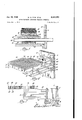
- Figure l is a vertical section taken through a high frequency transformer utilized for power for our system.
- Figure 2 is a perspective view showing one form of inductors used for inducing electric currents into the work.
- Figure 3 is a perspective view similar to Figure 2 showing a modied form of inductive means.
- Figure 4 is a transverse vertical sectional view through inductive means similar to that of Figure 3, and showing in addition, parts applied to the upper surface of the work sheets.
- Figure 5 is an enlarged vertical longitudinal section taken on the line 5-5 of Figure 4.
- Figure 6 is a perspective view of a further modified form of induction means incorporating our invention.
- Figure 7 is a vertical section taken on the line 'I--T of Figure 6.
- Figure 8 is a partial perspective view parts being broken away and shown in section revealing a still further modified form of induction means embodying our invention.
- Figure 9 is a transverse sectional view of a modified form of induction means similar to Figure 3.
- Figure 10 is an enlarged transverse sectional view taken on the line Ill-I0 of Figure 3.
- Figure 11 is a transverse sectional view through amodved form of induction means similar to that shown in Figure 8.
- Figure 12 is a schematic diagram showing the momentary direction of current flow and flux paths for the type of inductor shown in Figures 6 and 7.
- Figure 13 is a similar diagram for the inductors disclosed in Figures 2 and 3.
- the transformer shown in Fig. 1 will be briefly described herein but is speciiically claimed in Adivisional application S. N. 52,996, led October 6, 1948, and is especially adapted to be utilized for high frequency power and it comprises in outside appearance a large ring or torus having two axially spaced circular plates ln the center.
- lring per se is formed of a plurality of windings 2 forming the primary circuit of the transformer, which windings are formed into a ring.
- a circular insulating means 4 entirely covers this ring and insulates it from the so-called secondary winding which in this case is composed of a series of loops 6 around the ring and circumferentially spaced around the periphery thereof, the loops not being complete and having their end iianges 8 extend parallel to each other and permanently connected to two circular flat plates ID and I2 which are separated by an insulating layer I4.
- FIG. 2 there is shown therein the two plates lil and l2 of the transformer secondary, the latter having an openingV lf3 therein so that the inductors or work coils the drawings which is a top view looking down upon the three inductors.
- the arrows at the left of the figure illustrate the instantaneous flow of current in the inductors.
- the square A formed as they are referred to in this held to be used may be connected to the different plates as nearly together as possible.
- the front plate l2 carries a supporting block I8 to which is rigidly secured one inductor E20.
- This is formed of a member having a rectangular cross section whose rear portion is connected to the supporting block I8 and which projects at right angles to the plate l2. its center section is raised and both the front. and rear portions fall away to provide a central platform.
- a series of co-oling ducts 22 and 24 are provided in this member for the application of cooling fiuid when operating.
- inductors 2E and 28 On either side of the inductor 2B are two similar inductors 2E and 28 which have their greater dimensions turned at right angles to that of the first and expose their larger dimensionv asv ⁇ an inductor surface. Their inner ends are secured to the transformer plate l and, as in the case of the inductor 20, their central section is raised to provide a central platform for the actual parts to be welded. They also are provided with c001- ing ducts 22 and 2li for circulating the coolingV iiuid. 'A member 3l! is rigidly connected ⁇ r to the forwardly extending portion .of all of these ine ductors to connect them together electrically and permit fiuid flow therebetween.
- cooling water or other fluid is introduced into the rearmost portion of the three.
- indue-tors through insulated hoses or other similar devices so that water continuously circulates through them during operation. In this manner thel outer surfaces thereof are maintained reasonably cool and withdraw heat from the outer surface of the work-piece so that the same will remain relatively cool.
- the major plane of the part may be considered as parallel to the plane of support of the upper surface of the inductors, and therefore the currents induced in the parts are defined as being in plane cur- Since we are i* bracket. for cooling that member.
- .dash lines represents the metal sheets that are to be secured together and which might be termed work sheets.
- a flux is created around the same and the crosses H indicate such flux in the space ⁇ between inductors 2li and 28 as flowing away from the observer or into the paper.
- the circle and dot indications H2 designate flux flowing upward out of the paper. This generated flux therefore flows vup into the work sheets through them and down on the other side and as it does so induces currents in said sheets.
- FIG. 3 discloses, as before, transformer plates I0 and I2 and in this instance there is provided an ,angular flanged bracket member 32 rigidly secured tothe front transformer plate l2 which is adapted to act as an inductor and support additional apparatus.
- vA hollow coolant tube 34 is supported adjacent oneside of the angular bracket and a second similar tube 35 is supported on the opposite side.
- a third tube 38 is supported beneath the lowest portion of the angle
- the central portion of the angular bracket provides a rectangular depression .within which is carried the central inductor lll which is connected to the rear transformer plate ID.
- the inductor Il@ docs. not extend up to the level .of the horizontal flanged portionof the bracket 32 but carries a cooling duct 42 thereon which is insulated therefrom by aglayer of insulating material 44.
- the upper surface of the flanged member 32 and the upper surface -of the cooling duct40 provide a platform upon A and the cooling ducts.
- Figures 4 and 5 show substantially the same construction roffthe'terminals as Figure 3 except that the cooling tube 42 supported on the center inductor di! has been'replaced by a member 45 formed ofTransite.
- a member 45 formed ofTransite.
- the top sheet 52 means forming a pressure pad, since in all cases it is necessary to maintainthe work securely against the inductors.
- formed orl 'Transite 4or some similar material which is directly in contact with the upper surface of the sheet 52.
- a block 56 of rubber or other deformable material Above this Transite block is a block 56 of rubber or other deformable material.
- enclosing the blocks and in alignment with laminations 4B are several layers of laminations 58.
- the purpose of the pressure pad assembly is to maintain substantially a constant pressure on the metal during its molten period so that as it tends to expand and contract, it will be maintained within spaced limits and to concentrate thev magnetic field.
- Figure 9 illustrates a modified form of the same general inductor construction shown in Fig. 3 except that in this case the cooling tube 42 has been entirely removed and the conductive inductor du moved up to a position adjacent the top oi the depression in the terminal 32 and a layer of insulating material H8 placed over the inductors to prevent a short circuit. This may be used in instances where the removal of heat is not of tantamount importance. It also tends to reduce the inductance loop.
- a series of hollow, roughly rectangular tubes 62, 64, 66, 68 and 'l0 are rigidly secured to the transformer plate I0 and projected outwardly from its surface in spaced parallel relation.
- the uppermost tube 62 is the shortest and is bent upwardly at right angles and then into the form of a square, being again bent downwardly at the opposite side of a spaced gap and in turn connected back to the front transformer plate I2.
- the second tube 64 extends slightly further than the first, is again bent upwardly at its forward portion and is also bent around into the shape of a small square to nt concentrically within the larger square formed by the tube 62 and is spaced therefrom.
- the remaining tubes de, SS and 'l0 are formed in like manner to the tube previously described and form progressively smaller concentric squares.
- the central portion of the smallest square formed by the tube is iilled with laminations
- This pad may consist of a block 54 'l2 andthe gap 14 between the inner ends of the squares is occupied by two different sets of materials.
- a seriesof laminations 16 of magnetic material such as iron having a curved conguration toward the center of the gap, occupy the rear portion of this space, and a series of brass or copper laminations 'i8 ll the remainder.
- An additional set of laminations are supported along the inner edge of the square.
- Cooling tubes 82 and 843 for introducing water or other coolant from a source are connected to the tubes 62 through 'I0 to introduce the cooling fluid thereto.
- the parts to be welded are laid upon the top of the square formed by the various tubes, the actual point to be welded being positioned over the narrow neck portion 'I4 and in'alignment with the copper or brass laminations 18.
- Figure l2 illustrates diagrammatically the paths of current and flux for the construction shown in Figs. G and 7.
- the instantaneous current paths are shown at 20,
- the flux generated thereby will follow paths as indicated by the curved arrows 526 up into work sheets which may be supported by the tubes. This induces in-plane currents in the work sheets and it will be evident that these currents will flow across that portion above the gap 'M and be somewhat concentrated due to the high reactance of portions 'l2 and 8E.
- the brass or copper laminations are set at right angles to the current flow to prevent shunting currents and that being good heat conductors they assist in removing heat from the outer or lower surface.
- Fig. 8 The modification disclosed in Fig. 8 is similar to those set forth in the previous instances, except that in this case terminal means are applied both above and below the sheets or parts to be welded.
- These sheets in this case referred to as 86 and 88, are positioned between conductors or inductors 90, 52, 94 and 96 above and 98, illu,
- the two outside conductors in each instance are secured to one transformer plate and the two inside conductors to the other transformer plate.
- 06 and Hi8 are likewise applied to concentrate the magnetic eld. This concentration of the flux at the center of the box formed by the laminations, is suilcient to cause that portion to become molten or uid as shown at Ill.
- a plurality of conductive 'meansso shaped as to form concentric portions of a ⁇ platform for Work piece but spaced irom each other, said platform having an opening therethrough at one point, said conductive means being adapted to be connected to a source of high frequency power, a group of magnetic laminations mounted in said opening to partially iill the same and a second group of nonmagnetic laminations also mounted in the opening to fill the remainder, both groups tending to concentrate the current lin .and cool the surface of the Work respectively.
Landscapes
- Engineering & Computer Science (AREA)
- Mechanical Engineering (AREA)
- General Induction Heating (AREA)
Description
Jan. 10, 1950 w. G. DOW- ET A1.
HIGH-FREQUENCY INDUCTIVE WELDING APPARATUS 3 Sheets-Sheet 1 Filed Dec. l', 1944 lllll lllllll lllillllllll.. ,llll
W. G- DOW ET AL HIGH-FREQUENCY INDUCTIVE WELDING APPARATUS Jan. 10, 1950 3 Sheets-Sheet 2 Filed Dec. l, 1944 ttornegs Jan. l0, 1950 w. G. Dow ET Al. 2,493,950
HIGH-FREQUENCY INDUCTIVE WELDING APPARATUS Filed Dec. l, 1944 3 Sheets-Sheet 3 Patented Jan. 10, 1,950
HIGH-FREQUENCY INDUCTIVE WELDING APPARATUS William G. Dow and Harold C. Early, Boston. Mass., and Henry J. Gomberg, Washington, D. C., assignorsto General Motors Corporation, Detroit, Mich., a. corporation of Delaware Application December 1, 1944, Serial No. 566,052
2 Claims. l
This invention relates to means for securing members together in juxtaposition and more particularly to such means as is accomplished by high frequency induction welding.
In securing members together by welding, one of the problems involved is that of providing suiicient physical space or room adjacent the plurality of means conventionally necessary for applying the power as will enable the work to be readily and properly positioned. In other words, providing a sufficiently large throat so that the pieces to be welded can be satisfactorily applied to the electrodes or terminals.
It has been previously common to induce currents in metal bodies or sheets without actual conductive means, but these have been used largely for heating or heat treating and not for actually raising the temperature of the metal pieces above the fusion point for welding. If sufficient concentrated heat for fusion can be introduced by using induction methods, the question of a Welding throat is removed inasmuch as the induction may be from one side of the sheets only.
It is therefore an object of our invention to provide a novel welding means utilizing high frequency currents for securing members together.
It is a further object of our invention to provide novel inductive means operating at high frequencies for welding members together.
It is a still further object of our invention to provide suitable inductor means for inducing high frequency currents into the work.
It is a still further object of our invention to provide inductors for inducing heating currents into the work and concentrating these currents to cause fusion of the metal.
With these and other objects in View which will become apparent as the specification proceeds. the embodiments of our invention will'be best understood by reference to the following specification and claims and the illustrations in the accompanying drawings, in which: g
Figure l is a vertical section taken through a high frequency transformer utilized for power for our system.
Figure 2 is a perspective view showing one form of inductors used for inducing electric currents into the work.
Figure 3 is a perspective view similar to Figure 2 showing a modied form of inductive means.
Figure 4 is a transverse vertical sectional view through inductive means similar to that of Figure 3, and showing in addition, parts applied to the upper surface of the work sheets.
Figure 5 is an enlarged vertical longitudinal section taken on the line 5-5 of Figure 4.
Figure 6 is a perspective view of a further modified form of induction means incorporating our invention.
" Figure 7 is a vertical section taken on the line 'I--T of Figure 6.
Figure 8 is a partial perspective view parts being broken away and shown in section revealing a still further modified form of induction means embodying our invention.
Figure 9 is a transverse sectional view of a modified form of induction means similar to Figure 3.
'Figure 10 is an enlarged transverse sectional view taken on the line Ill-I0 of Figure 3.
' Figure 11 is a transverse sectional view through amodiiled form of induction means similar to that shown in Figure 8.
Figure 12 is a schematic diagram showing the momentary direction of current flow and flux paths for the type of inductor shown in Figures 6 and 7.
Figure 13 is a similar diagram for the inductors disclosed in Figures 2 and 3.
Referring now more specifically to the drawings, since we are utilizing frequencies which are considerably above the ordinary power frequencies and are at the same time utilizing fairly heavy power, it is necessary to use special transformers between the source of such high frequency power and the application of the same to the work.
The transformer shown in Fig. 1 will be briefly described herein but is speciiically claimed in Adivisional application S. N. 52,996, led October 6, 1948, and is especially adapted to be utilized for high frequency power and it comprises in outside appearance a large ring or torus having two axially spaced circular plates ln the center. The
lring per se is formed of a plurality of windings 2 forming the primary circuit of the transformer, which windings are formed into a ring. A circular insulating means 4 entirely covers this ring and insulates it from the so-called secondary winding which in this case is composed of a series of loops 6 around the ring and circumferentially spaced around the periphery thereof, the loops not being complete and having their end iianges 8 extend parallel to each other and permanently connected to two circular flat plates ID and I2 which are separated by an insulating layer I4.
Thus, all of the secondary loops 6 form a single turn secondary and all have one end connected to plate Il! and the other to plate I2. Thus, these two plates form the terminals of the secondary circuit. Therefore, upon current being introduced into the primary winding 2 from the oscillator or other source of high frequency current, current will be induced in the ratio of the primary turns to one and the secondary output from plates le and l2 will go directly to the inductors. In this manner the leads in the secondary circuit may be kept to a minimum length providing a very low value of leakage reactance and a minimum inductance loop.
Referring now to Figure 2 there is shown therein the two plates lil and l2 of the transformer secondary, the latter having an openingV lf3 therein so that the inductors or work coils the drawings which is a top view looking down upon the three inductors. The arrows at the left of the figure illustrate the instantaneous flow of current in the inductors. The square A formed as they are referred to in this held to be used may be connected to the different plates as nearly together as possible. In Fig. 2 the front plate l2 carries a supporting block I8 to which is rigidly secured one inductor E20. This is formed of a member having a rectangular cross section whose rear portion is connected to the supporting block I8 and which projects at right angles to the plate l2. its center section is raised and both the front. and rear portions fall away to provide a central platform. A series of co-oling ducts 22 and 24 are provided in this member for the application of cooling fiuid when operating.
On either side of the inductor 2B are two similar inductors 2E and 28 which have their greater dimensions turned at right angles to that of the first and expose their larger dimensionv asv `an inductor surface. Their inner ends are secured to the transformer plate l and, as in the case of the inductor 20, their central section is raised to provide a central platform for the actual parts to be welded. They also are provided with c001- ing ducts 22 and 2li for circulating the coolingV iiuid. 'A member 3l! is rigidly connected`r to the forwardly extending portion .of all of these ine ductors to connect them together electrically and permit fiuid flow therebetween.
In operation, cooling water or other fluid is introduced into the rearmost portion of the three. indue-tors through insulated hoses or other similar devices so that water continuously circulates through them during operation. In this manner thel outer surfaces thereof are maintained reasonably cool and withdraw heat from the outer surface of the work-piece so that the same will remain relatively cool.
When the transformer is energized, currentwill flow, depending, of course, upon the polarity, out through the inductor 25 and back into the two inductors 26 and 28 to the opposite transformer plate s' 1l which will create certain magnetic fields.
When, therefore, two superimposed sheets of metal are laid upon the platform provided by the raised portions; of the inductors 2U, 26 and 28, and separated therefrom by a thinfsheet of insulating material, this flow of current will create a flux which passes into the worksheets and induces therein currents iiowing inv the planes of said sheets. These currents which are induced in the sheets or parts that itis desired to weld together and which may be termed work sheets, by the fields created by the"inductors flow within the physical dimensions of the sheets. assuming that in the majority of instances the parts to be welded will have much greater length and width dimensions than thickness, the major plane of the part may be considered as parallel to the plane of support of the upper surface of the inductors, and therefore the currents induced in the parts are defined as being in plane cur- Since we are i* bracket. for cooling that member.
of .dash lines represents the metal sheets that are to be secured together and which might be termed work sheets. When current flows through a conductor a flux is created around the same and the crosses H indicate such flux in the space `between inductors 2li and 28 as flowing away from the observer or into the paper. On the other side in the space between inductors 2i! and 26 the circle and dot indications H2 designate flux flowing upward out of the paper. This generated flux therefore flows vup into the work sheets through them and down on the other side and as it does so induces currents in said sheets.
These currents are shown by the dash oval figures H4 and HE. It will be noted that such current paths are double in the central part, where they support each other or add, to the strength in either of the outer surfaces. This concentrated in-plane current ow will be of suilicient intensity to cause a rise in temperature at this concentrated point sufficient to melt the metal and cause a weld between the two parts. This rise in temperature wouldalso be likely to affect the outer surface of the lower sheet, but since the inductors themselves are maintained relatively cool bythe flow of liquid therein, the heat is conducted away fromv this surface with sufficient rapidity lto tend to prevent its becoming molten. Therefore, welds will occur in the sheets applied to the induction means shown in Fig. 2 in a central plane above the middle inductor 20.
The modification of Figures 3 and l0 of this application discloses, as before, transformer plates I0 and I2 and in this instance there is provided an ,angular flanged bracket member 32 rigidly secured tothe front transformer plate l2 which is adapted to act as an inductor and support additional apparatus. vA hollow coolant tube 34is supported adjacent oneside of the angular bracket and a second similar tube 35 is supported on the opposite side. A third tube 38 is supported beneath the lowest portion of the angle The central portion of the angular bracket provides a rectangular depression .within which is carried the central inductor lll which is connected to the rear transformer plate ID. The inductor Il@ docs. not extend up to the level .of the horizontal flanged portionof the bracket 32 but carries a cooling duct 42 thereon which is insulated therefrom by aglayer of insulating material 44.
A series. of ytransformer laminations 'l5 con forming in shape to the depression in member 32- fill the space between the central inductor 4i) and the frame member 32. The upper surface of the flanged member 32 and the upper surface -of the cooling duct40 provide a platform upon A and the cooling ducts.
Figures 4 and 5 show substantially the same construction roffthe'terminals as Figure 3 except that the cooling tube 42 supported on the center inductor di! has been'replaced by a member 45 formed ofTransite. However in addition there is applied above the top sheet 52, means forming a pressure pad, since in all cases it is necessary to maintainthe work securely against the inductors. formed orl 'Transite 4or some similar material which is directly in contact with the upper surface of the sheet 52. Above this Transite block is a block 56 of rubber or other deformable material. In turn, enclosing the blocks and in alignment with laminations 4B are several layers of laminations 58. The purpose of the pressure pad assembly is to maintain substantially a constant pressure on the metal during its molten period so that as it tends to expand and contract, it will be maintained within spaced limits and to concentrate thev magnetic field.
Inv this instance, when current is introduced into the transformer disks, it will flow out through one inductor. mom'entarily, for example, the centrai one du returning through the two side flanges 52 to the ropposite transformer disk and then reverse. This will create a ux which will interlink with the work sheets 50 and 52, concentrating the same substantially between the lamination piles lfd and 58. This flux will again induce in-plane currents inthe sheets 50 and 52, which currents Vwill be of sufficient strength to raise predetermined portions of the sheet above their melting points and vweld the two together in these small concentratedrareas. Here again, the cooling ducts will remove the heat from the outer surface of the sheets so that they will not be too greatly affected by the high temperatures. When the metal becomes molten, the Transite sheet 54 will protect the rubber or deformable pad 56 from the intensive heat but will allow the latter to cause surface pressure downward on the work sheet 5?; and press the sheets rmly together to cause a satisfactory weld.
Figure 9 illustrates a modified form of the same general inductor construction shown in Fig. 3 except that in this case the cooling tube 42 has been entirely removed and the conductive inductor du moved up to a position adjacent the top oi the depression in the terminal 32 and a layer of insulating material H8 placed over the inductors to prevent a short circuit. This may be used in instances where the removal of heat is not of tantamount importance. It also tends to reduce the inductance loop.
Referring now to the modications shown in Figures 6 and 7, a series of hollow, roughly rectangular tubes 62, 64, 66, 68 and 'l0 are rigidly secured to the transformer plate I0 and projected outwardly from its surface in spaced parallel relation. The uppermost tube 62 is the shortest and is bent upwardly at right angles and then into the form of a square, being again bent downwardly at the opposite side of a spaced gap and in turn connected back to the front transformer plate I2. The second tube 64 extends slightly further than the first, is again bent upwardly at its forward portion and is also bent around into the shape of a small square to nt concentrically within the larger square formed by the tube 62 and is spaced therefrom. The remaining tubes de, SS and 'l0 are formed in like manner to the tube previously described and form progressively smaller concentric squares.
The central portion of the smallest square formed by the tube is iilled with laminations This pad may consist of a block 54 'l2 andthe gap 14 between the inner ends of the squares is occupied by two different sets of materials. A seriesof laminations 16 of magnetic material such as iron having a curved conguration toward the center of the gap, occupy the rear portion of this space, and a series of brass or copper laminations 'i8 ll the remainder. An additional set of laminations are supported along the inner edge of the square. Cooling tubes 82 and 843 for introducing water or other coolant from a source are connected to the tubes 62 through 'I0 to introduce the cooling fluid thereto.
In this instance, the parts to be welded are laid upon the top of the square formed by the various tubes, the actual point to be welded being positioned over the narrow neck portion 'I4 and in'alignment with the copper or brass laminations 18.
Figure l2 illustrates diagrammatically the paths of current and flux for the construction shown in Figs. G and 7. The instantaneous current paths are shown at 20, |22 and E24 and form parallel reactance paths with a substantially equal distribution of current. On an assumed direction of current flow as shown by the arrows the flux generated thereby will follow paths as indicated by the curved arrows 526 up into work sheets which may be supported by the tubes. This induces in-plane currents in the work sheets and it will be evident that these currents will flow across that portion above the gap 'M and be somewhat concentrated due to the high reactance of portions 'l2 and 8E. However, since this is a relatively wide gap, it is desired to further concentrate or neck down this flow which is done by the insertion of iron laminations '.15 which increases the reactance of that portion of the gaps forcing the current lines closer together over that portion above the brass laminations 18. This produces a very high in-plane current directly above the brass laminations and causes a weld at that point.
It might also be mentioned that the brass or copper laminations are set at right angles to the current flow to prevent shunting currents and that being good heat conductors they assist in removing heat from the outer or lower surface.
The modification disclosed in Fig. 8 is similar to those set forth in the previous instances, except that in this case terminal means are applied both above and below the sheets or parts to be welded. These sheets, in this case referred to as 86 and 88, are positioned between conductors or inductors 90, 52, 94 and 96 above and 98, illu, |02 and |04 below. The two outside conductors in each instance are secured to one transformer plate and the two inside conductors to the other transformer plate. A series of laminations |06 and Hi8 are likewise applied to concentrate the magnetic eld. This concentration of the flux at the center of the box formed by the laminations, is suilcient to cause that portion to become molten or uid as shown at Ill. A heat resistant member l i3 below and a similar one above, maintain the fluid metal in position. In this instance, the heating extends entirely through these sheets and forms a weld section similar to the contour of a rivet.
It will be noted in Fig. 8 that the leg portions of the laminations IIJB or that portion extending to the work sheets are straight. That is, there is the same distance between the two legs at the bottom of the cavity within which the inductors |00 and H12 lie as there is at the top. Figure 11 however discloses a modified form of lamination structure in that that vportion of the lamination nearest the work sheet is .of greater dimension to provide a narrower :air gap. In that .case the terminals 98, 109, `IIlZand vH14 .are shown as before but the lamination structure |96 is provided .with projecting portions 130 and v:|32 which extend toward each other adjacent the vwork sheets. This leaves a much smaller .gap between the legs of the lamination. A member` |34 of Transite is supported in this gap by any suitable Ymeans to back up the welding portion. This construction has the advantage of reduced Vleakage inductance making a lower power input necessary Aand still provides a space for cooling if desired.
It will thus be evident from the foregoing that we have provided vmeans for welding with high frequency currents, members which may be applied to inductor surfaces and the heat generated by the current induced therein, preferably from one surface only.
We claim:
1. In high frequency welding .me-ans, a plurality of conductive 'meansso shaped as to form concentric portions of a `platform for Work piece but spaced irom each other, said platform having an opening therethrough at one point, said conductive means being adapted to be connected to a source of high frequency power, a group of magnetic laminations mounted in said opening to partially iill the same and a second group of nonmagnetic laminations also mounted in the opening to fill the remainder, both groups tending to concentrate the current lin .and cool the surface of the Work respectively.
2. In high frequency welding means, a plurality of spaced conductive members arranged to form concentric portions kof a platform for a work-piece, said .platform having van opening therethrough at one point, a source of power, a plurality of conductors extending from the ends ofthe members to the source, the lengths of said conductors being in inverse relation to the lengths of the members to Which they are connected so REFERENCES -CITED The following references are of 'record in the file of this patent:
UNITED STATES PATENTS Number Name Date 1,809,468 Bornand etal June 9, 1931 1,861,869 Long June 7, 1932 1,915,047 Blakeslee June 20, 1933 1,932,423 vSessions Oct. l31, 1933 1,997,741 Northrup Apr. 16, 1935 2,003,855 Fredrickson June 4, 1935 2,144,378 Kennedy Jan. 17, 1939 2,151,035 Kennedy Mar. 21, 1939 2,176,488 Dreyfus Oct. 17, 1939 2,181,899 Kennedy Dec. 5, 1939 '2,182,341 Hulster Dec. 5, 1939 2,194,231 AClark Dec. 26, 1939 2,217,546 Hagedorn Oct. 8, 1940 2,318,468 Denneen et a1 May 4, 1943 2,348,361 Rudd et al May 9, 1944 2,355,560 Roberds Aug. y8, 1944 2,367,715 lChapman Jan. 23, 1945 FOREIGN PATENTS Number Country Date 467,308 Great Britain June 15, 1937 OTHER REFERENCES fSer. No. 387,342, -Gumprecht (A. P. 0.), published June 1, 1943.
Priority Applications (1)
| Application Number | Priority Date | Filing Date | Title |
|---|---|---|---|
| US566052A US2493950A (en) | 1944-12-01 | 1944-12-01 | High-frequency inductive welding apparatus |
Applications Claiming Priority (1)
| Application Number | Priority Date | Filing Date | Title |
|---|---|---|---|
| US566052A US2493950A (en) | 1944-12-01 | 1944-12-01 | High-frequency inductive welding apparatus |
Publications (1)
| Publication Number | Publication Date |
|---|---|
| US2493950A true US2493950A (en) | 1950-01-10 |
Family
ID=24261270
Family Applications (1)
| Application Number | Title | Priority Date | Filing Date |
|---|---|---|---|
| US566052A Expired - Lifetime US2493950A (en) | 1944-12-01 | 1944-12-01 | High-frequency inductive welding apparatus |
Country Status (1)
| Country | Link |
|---|---|
| US (1) | US2493950A (en) |
Cited By (30)
| Publication number | Priority date | Publication date | Assignee | Title |
|---|---|---|---|---|
| US2574855A (en) * | 1948-07-17 | 1951-11-13 | Warner Swasey Co | Induction hardening of ways of machine tools |
| US2599229A (en) * | 1948-03-30 | 1952-06-03 | Gen Electric | Work coil |
| US2631215A (en) * | 1950-08-24 | 1953-03-10 | Ford Motor Co | Welding system |
| US2632092A (en) * | 1949-06-09 | 1953-03-17 | Ohio Crankshaft Co | Means and method for high-frequency induction heating |
| US2632840A (en) * | 1948-11-04 | 1953-03-24 | Ohio Crankshaft Co | Means for inductively heating narrow elongated portions of cylindrical bodies |
| US2635177A (en) * | 1951-04-26 | 1953-04-14 | Ohio Crankshaft Co | High-frequency inductor arrangement |
| US2649527A (en) * | 1951-01-18 | 1953-08-18 | Combustion Eng | Butt welding tube ends by induction heating |
| US2655589A (en) * | 1950-06-03 | 1953-10-13 | Ohio Crankshaft Co | High-frequency inductor |
| US2671846A (en) * | 1950-02-28 | 1954-03-09 | Ohio Crankshaft Co | Means for inductively heating narrow elongated portions of cylindrical bodies |
| US2672544A (en) * | 1948-11-30 | 1954-03-16 | Marocaine Tech Et Commerciale | Apparatus for welding by means of electromagnetic induction heating |
| US2673274A (en) * | 1950-07-29 | 1954-03-23 | Ohio Crankshaft Co | Strip heating |
| US2689296A (en) * | 1949-06-09 | 1954-09-14 | Ohio Crankshaft Co | Means and method of high-frequency induction heating |
| US2710901A (en) * | 1950-09-25 | 1955-06-14 | Mcgraw Electric Co | Method and machine for brazing electric iron body assemblies |
| US2715170A (en) * | 1949-04-07 | 1955-08-09 | Ohio Crankshaft Co | Method and means for inductively heating narrow elongated portions of cylindrical bodies |
| US2737563A (en) * | 1950-05-20 | 1956-03-06 | Yoder Co | Methods of and apparatus for making tubes |
| US2749423A (en) * | 1951-08-01 | 1956-06-05 | Hartford Nat Bank & Trust Co | Device for high-frequency heating |
| US2751481A (en) * | 1951-04-20 | 1956-06-19 | Hartford Nat Bank & Trust Co | Clamping device intended for the electrical connection of a work-coil for the inductive heating of work-pieces to the secondary winding of the output coil of a high-frequency |
| US2762894A (en) * | 1951-03-17 | 1956-09-11 | Ohio Crankshaft Co | Apparatus for high-frequency induction heating of small-diameter wire |
| US2768269A (en) * | 1950-11-30 | 1956-10-23 | Delapena & Son Ltd | High frequency induction heating apparatus |
| US2777041A (en) * | 1953-05-21 | 1957-01-08 | Lindberg Eng Co | High frequency heat treating apparatus |
| US2785263A (en) * | 1952-03-28 | 1957-03-12 | Philips Corp | Method for the local heating of metallic work-pieces by inductive hf-heating and hf-inductor |
| US2788425A (en) * | 1951-03-17 | 1957-04-09 | Chester A Tudbury | High-frequency inductor arrangement |
| US2810053A (en) * | 1955-09-26 | 1957-10-15 | Ohio Crankshaft Co | High frequency inductor for small diameter holes |
| US2810054A (en) * | 1954-08-17 | 1957-10-15 | Delapena & Son Ltd | Apparatus for heating toothed or serrated portions of articles by high frequency induction heating |
| DE1060518B (en) * | 1955-04-16 | 1959-07-02 | Deutsche Edelstahlwerke Ag | Device for progressive induction welding |
| DE973775C (en) * | 1951-01-18 | 1960-06-02 | Combustion Eng | Device for butt welding the ends of metal pipes |
| US3242299A (en) * | 1963-10-17 | 1966-03-22 | Ohio Crankshaft Co | Inductor for induction heating apparatus |
| US3301991A (en) * | 1963-06-07 | 1967-01-31 | Deutsche Edelstahlwerke Ag | Inductor for heating the ends of elongated stock |
| EP0150165A3 (en) * | 1984-01-24 | 1987-12-16 | Ab Akerlund & Rausing | A device for induction welding |
| US20130140299A1 (en) * | 2011-12-05 | 2013-06-06 | Neturen Co., Ltd. | Heating coil |
Citations (18)
| Publication number | Priority date | Publication date | Assignee | Title |
|---|---|---|---|---|
| US1809468A (en) * | 1929-02-19 | 1931-06-09 | Bornand Emilien | Electric metal welding |
| US1861869A (en) * | 1930-09-20 | 1932-06-07 | Westinghouse Electric & Mfg Co | Adjustable induction heating device |
| US1915047A (en) * | 1930-10-29 | 1933-06-20 | Doraf W Blakeslee | Method of electric welding |
| US1932423A (en) * | 1929-08-22 | 1933-10-31 | Frank L Sessions | Apparatus for electric induction welding and heating |
| US1997741A (en) * | 1933-05-02 | 1935-04-16 | Ajax Electrothermic Corp | Muffle inductor electric furnace |
| US2003855A (en) * | 1931-07-11 | 1935-06-04 | Gen Motors Corp | Electric heater |
| GB467308A (en) * | 1936-09-19 | 1937-06-15 | Francis Stanislaus Denneen | Improvements relating to the joining or connection of parts by fusing |
| US2144378A (en) * | 1937-09-11 | 1939-01-17 | Ajax Electrothermic Corp | Induction heater |
| US2151035A (en) * | 1937-12-11 | 1939-03-21 | Ajax Electrothermic Corp | Transformer |
| US2176488A (en) * | 1935-12-18 | 1939-10-17 | Asea Ab | Furnace for heating pieces by means of high frequency currents |
| US2182341A (en) * | 1937-09-07 | 1939-12-05 | Telefunken Gmbh | Radio tube manufacture |
| US2181899A (en) * | 1939-01-26 | 1939-12-05 | Ajax Electrothermic Corp | Transformer |
| US2184281A (en) * | 1935-07-26 | 1939-12-26 | Armstrong Cork Co | Method of making closures |
| US2217546A (en) * | 1937-10-09 | 1940-10-08 | Bernhard Berghaus | Electric resistance welding |
| US2318468A (en) * | 1941-08-06 | 1943-05-04 | Ohio Crankshaft Co | Adjustable heating apparatus |
| US2348361A (en) * | 1943-06-24 | 1944-05-09 | Induction Heating Corp | Adjustable work coil construction for induction heating |
| US2355560A (en) * | 1943-02-27 | 1944-08-08 | Rca Corp | Electrical coupling device |
| US2367715A (en) * | 1943-12-18 | 1945-01-23 | Chapman Everett | Method and apparatus for metal treatment and fabrication |
-
1944
- 1944-12-01 US US566052A patent/US2493950A/en not_active Expired - Lifetime
Patent Citations (18)
| Publication number | Priority date | Publication date | Assignee | Title |
|---|---|---|---|---|
| US1809468A (en) * | 1929-02-19 | 1931-06-09 | Bornand Emilien | Electric metal welding |
| US1932423A (en) * | 1929-08-22 | 1933-10-31 | Frank L Sessions | Apparatus for electric induction welding and heating |
| US1861869A (en) * | 1930-09-20 | 1932-06-07 | Westinghouse Electric & Mfg Co | Adjustable induction heating device |
| US1915047A (en) * | 1930-10-29 | 1933-06-20 | Doraf W Blakeslee | Method of electric welding |
| US2003855A (en) * | 1931-07-11 | 1935-06-04 | Gen Motors Corp | Electric heater |
| US1997741A (en) * | 1933-05-02 | 1935-04-16 | Ajax Electrothermic Corp | Muffle inductor electric furnace |
| US2184281A (en) * | 1935-07-26 | 1939-12-26 | Armstrong Cork Co | Method of making closures |
| US2176488A (en) * | 1935-12-18 | 1939-10-17 | Asea Ab | Furnace for heating pieces by means of high frequency currents |
| GB467308A (en) * | 1936-09-19 | 1937-06-15 | Francis Stanislaus Denneen | Improvements relating to the joining or connection of parts by fusing |
| US2182341A (en) * | 1937-09-07 | 1939-12-05 | Telefunken Gmbh | Radio tube manufacture |
| US2144378A (en) * | 1937-09-11 | 1939-01-17 | Ajax Electrothermic Corp | Induction heater |
| US2217546A (en) * | 1937-10-09 | 1940-10-08 | Bernhard Berghaus | Electric resistance welding |
| US2151035A (en) * | 1937-12-11 | 1939-03-21 | Ajax Electrothermic Corp | Transformer |
| US2181899A (en) * | 1939-01-26 | 1939-12-05 | Ajax Electrothermic Corp | Transformer |
| US2318468A (en) * | 1941-08-06 | 1943-05-04 | Ohio Crankshaft Co | Adjustable heating apparatus |
| US2355560A (en) * | 1943-02-27 | 1944-08-08 | Rca Corp | Electrical coupling device |
| US2348361A (en) * | 1943-06-24 | 1944-05-09 | Induction Heating Corp | Adjustable work coil construction for induction heating |
| US2367715A (en) * | 1943-12-18 | 1945-01-23 | Chapman Everett | Method and apparatus for metal treatment and fabrication |
Cited By (31)
| Publication number | Priority date | Publication date | Assignee | Title |
|---|---|---|---|---|
| US2599229A (en) * | 1948-03-30 | 1952-06-03 | Gen Electric | Work coil |
| US2574855A (en) * | 1948-07-17 | 1951-11-13 | Warner Swasey Co | Induction hardening of ways of machine tools |
| US2632840A (en) * | 1948-11-04 | 1953-03-24 | Ohio Crankshaft Co | Means for inductively heating narrow elongated portions of cylindrical bodies |
| US2672544A (en) * | 1948-11-30 | 1954-03-16 | Marocaine Tech Et Commerciale | Apparatus for welding by means of electromagnetic induction heating |
| US2715170A (en) * | 1949-04-07 | 1955-08-09 | Ohio Crankshaft Co | Method and means for inductively heating narrow elongated portions of cylindrical bodies |
| US2632092A (en) * | 1949-06-09 | 1953-03-17 | Ohio Crankshaft Co | Means and method for high-frequency induction heating |
| US2689296A (en) * | 1949-06-09 | 1954-09-14 | Ohio Crankshaft Co | Means and method of high-frequency induction heating |
| US2671846A (en) * | 1950-02-28 | 1954-03-09 | Ohio Crankshaft Co | Means for inductively heating narrow elongated portions of cylindrical bodies |
| US2737563A (en) * | 1950-05-20 | 1956-03-06 | Yoder Co | Methods of and apparatus for making tubes |
| US2655589A (en) * | 1950-06-03 | 1953-10-13 | Ohio Crankshaft Co | High-frequency inductor |
| US2673274A (en) * | 1950-07-29 | 1954-03-23 | Ohio Crankshaft Co | Strip heating |
| US2631215A (en) * | 1950-08-24 | 1953-03-10 | Ford Motor Co | Welding system |
| US2710901A (en) * | 1950-09-25 | 1955-06-14 | Mcgraw Electric Co | Method and machine for brazing electric iron body assemblies |
| US2768269A (en) * | 1950-11-30 | 1956-10-23 | Delapena & Son Ltd | High frequency induction heating apparatus |
| US2649527A (en) * | 1951-01-18 | 1953-08-18 | Combustion Eng | Butt welding tube ends by induction heating |
| DE973775C (en) * | 1951-01-18 | 1960-06-02 | Combustion Eng | Device for butt welding the ends of metal pipes |
| US2788425A (en) * | 1951-03-17 | 1957-04-09 | Chester A Tudbury | High-frequency inductor arrangement |
| US2762894A (en) * | 1951-03-17 | 1956-09-11 | Ohio Crankshaft Co | Apparatus for high-frequency induction heating of small-diameter wire |
| US2751481A (en) * | 1951-04-20 | 1956-06-19 | Hartford Nat Bank & Trust Co | Clamping device intended for the electrical connection of a work-coil for the inductive heating of work-pieces to the secondary winding of the output coil of a high-frequency |
| US2635177A (en) * | 1951-04-26 | 1953-04-14 | Ohio Crankshaft Co | High-frequency inductor arrangement |
| US2749423A (en) * | 1951-08-01 | 1956-06-05 | Hartford Nat Bank & Trust Co | Device for high-frequency heating |
| US2785263A (en) * | 1952-03-28 | 1957-03-12 | Philips Corp | Method for the local heating of metallic work-pieces by inductive hf-heating and hf-inductor |
| US2777041A (en) * | 1953-05-21 | 1957-01-08 | Lindberg Eng Co | High frequency heat treating apparatus |
| US2810054A (en) * | 1954-08-17 | 1957-10-15 | Delapena & Son Ltd | Apparatus for heating toothed or serrated portions of articles by high frequency induction heating |
| DE1060518B (en) * | 1955-04-16 | 1959-07-02 | Deutsche Edelstahlwerke Ag | Device for progressive induction welding |
| US2810053A (en) * | 1955-09-26 | 1957-10-15 | Ohio Crankshaft Co | High frequency inductor for small diameter holes |
| US3301991A (en) * | 1963-06-07 | 1967-01-31 | Deutsche Edelstahlwerke Ag | Inductor for heating the ends of elongated stock |
| US3242299A (en) * | 1963-10-17 | 1966-03-22 | Ohio Crankshaft Co | Inductor for induction heating apparatus |
| EP0150165A3 (en) * | 1984-01-24 | 1987-12-16 | Ab Akerlund & Rausing | A device for induction welding |
| US20130140299A1 (en) * | 2011-12-05 | 2013-06-06 | Neturen Co., Ltd. | Heating coil |
| US10582575B2 (en) * | 2011-12-05 | 2020-03-03 | Neturen Co., Ltd. | Heating coil |
Similar Documents
| Publication | Publication Date | Title |
|---|---|---|
| US2493950A (en) | High-frequency inductive welding apparatus | |
| US2416047A (en) | Combined reactor and induction preheater for use in electrode arc welding | |
| US3531612A (en) | Means for heating by induction | |
| US2818483A (en) | Method and apparatus for preheating can body side seams | |
| US3755644A (en) | High frequency induction heating apparatus | |
| US2632079A (en) | Means and method for electric seam welding | |
| US2059300A (en) | Apparatus for the formation of articles by welding | |
| US2708704A (en) | Electric heating coil structure | |
| US3331909A (en) | Apparatus for energizing an induction melting furnace with a three phase electrical network | |
| US3143628A (en) | Two turn inductor block with integral quench | |
| US1809468A (en) | Electric metal welding | |
| US3248512A (en) | Apparatus for welding metal tubing | |
| US2517425A (en) | Arrangement of electronic discharge tube equipment for the thermal treatment of metals by high-frequency currents | |
| US2485843A (en) | High-frequency heating arrangement | |
| US1937065A (en) | Induction furnace and method of operating the same | |
| US2233526A (en) | Apparatus for double spot or seam welding | |
| USRE24462E (en) | Dreyfus | |
| US2525336A (en) | Method for simultaneously induction heating a plurality of elements | |
| US3518394A (en) | Output transformer and work inductor for induction generators | |
| US2394944A (en) | Induction heating apparatus | |
| US2832876A (en) | Inductor arrangement for induction heating | |
| US2716689A (en) | High-frequency induction seam welding | |
| US2001179A (en) | Electric arc welding | |
| JP3305530B2 (en) | Floating melting equipment | |
| US2513376A (en) | Induction heating coil |