US2492472A - Speed responsive control system - Google Patents
Speed responsive control system Download PDFInfo
- Publication number
- US2492472A US2492472A US616030A US61603045A US2492472A US 2492472 A US2492472 A US 2492472A US 616030 A US616030 A US 616030A US 61603045 A US61603045 A US 61603045A US 2492472 A US2492472 A US 2492472A
- Authority
- US
- United States
- Prior art keywords
- speed
- network
- bridge
- condenser
- resistance
- Prior art date
- Legal status (The legal status is an assumption and is not a legal conclusion. Google has not performed a legal analysis and makes no representation as to the accuracy of the status listed.)
- Expired - Lifetime
Links
- 239000004020 conductor Substances 0.000 description 5
- 239000000446 fuel Substances 0.000 description 4
- 238000000034 method Methods 0.000 description 3
- 230000010349 pulsation Effects 0.000 description 3
- 230000001105 regulatory effect Effects 0.000 description 3
- 230000001419 dependent effect Effects 0.000 description 2
- 238000010586 diagram Methods 0.000 description 2
- 235000008694 Humulus lupulus Nutrition 0.000 description 1
- 244000025221 Humulus lupulus Species 0.000 description 1
- 238000010276 construction Methods 0.000 description 1
- 230000003247 decreasing effect Effects 0.000 description 1
- 238000007599 discharging Methods 0.000 description 1
- 238000005259 measurement Methods 0.000 description 1
- 230000002441 reversible effect Effects 0.000 description 1
- 238000004804 winding Methods 0.000 description 1
Images
Classifications
-
- H—ELECTRICITY
- H02—GENERATION; CONVERSION OR DISTRIBUTION OF ELECTRIC POWER
- H02P—CONTROL OR REGULATION OF ELECTRIC MOTORS, ELECTRIC GENERATORS OR DYNAMO-ELECTRIC CONVERTERS; CONTROLLING TRANSFORMERS, REACTORS OR CHOKE COILS
- H02P23/00—Arrangements or methods for the control of AC motors characterised by a control method other than vector control
- H02P23/16—Controlling the angular speed of one shaft
-
- Y—GENERAL TAGGING OF NEW TECHNOLOGICAL DEVELOPMENTS; GENERAL TAGGING OF CROSS-SECTIONAL TECHNOLOGIES SPANNING OVER SEVERAL SECTIONS OF THE IPC; TECHNICAL SUBJECTS COVERED BY FORMER USPC CROSS-REFERENCE ART COLLECTIONS [XRACs] AND DIGESTS
- Y10—TECHNICAL SUBJECTS COVERED BY FORMER USPC
- Y10T—TECHNICAL SUBJECTS COVERED BY FORMER US CLASSIFICATION
- Y10T137/00—Fluid handling
- Y10T137/0971—Speed responsive valve control
Definitions
- This invention concerns improvements in or relating to speed governing or temperature regulating.
- the present invention makes use of a known method for accurately determining the capacity of a condenser which is due to Clerk Maxwell.
- the condenser whose capacity is to be measured is substituted for one arm of a Wheatstone bridge-network.
- a commutator is also connected in this arm by means of which the condenser is alternately charged and discharged.
- the commutator is driven by an electric motor, supplied from a steady source, and whose speed can be varied as required.
- the charging current is applied to the bridge-network from a battery in the same way as for a Wheatstone bridge.
- the galvanometer is aiiected by a constant current which flows along the galvanometer branch in one direction and by a series of current impulses which flow along the branch in the opposite direction. These pulsations are produced in the network by the condenser being alternately charged and discharged.
- the steady current and the mean value of the impulses are equal (that is the net current flow in the galvanometer branch is zero) so that if the impulse frequency is suificiently high and the galvanometer has a linear response it will not be deflected.
- the galvanometer When the bridge-network is unbalanced, however, the galvanometer will defleet to an extent proportional to the difference between the steady current and the mean value of the current impulses, that is, to an extent proportional to the net current flow in the galvanometer branch.
- C is the condenser capacity
- P, Q, R are the resistances of the arms of the Wheatstone bridge
- 11b is the frequency of the commutator
- S is the resistance of the network.
- the net galvanometer current at m is zero and that at any other value n; it is i l.
- the value of the net galvanometer current is therefore solely dependent upon the frequency of the commutator.
- the range of the galvanometer deflections may be arbitrarily selected to indicate any desired range of frequency 1th to m in which m is greater or less than m.
- the modified Wheatstone bridge described above comprising the three resistance arms, the condenser arm and the commutator associated therewith will be referred to as a Maxwell bridge-network.”
- the points of the network across which the galvanometer would normally be connected will be referred to as the "output points of the network, although during balance of the bridge there is no net current flow from one to the other of said points.
- a method of speed-governing is characterised in that a source of direct current is adapted to be applied to a Maxwell bridge-network the condenser of which is alternately charged therefrom and discharged with a frequency proportional to the speed to be governed, and the output points of the network are connected to electrical means which is brought into operation upon a difference between the value of the steady current and the mean value of the current impulses being established consequent upon the speed to be governed departing. from a datum value corresponding to a state of balance in the bridge, said means being effective automatically to adjust the speed to be governed to restore the datum value thereof and re-establish balance in the bridge-network.
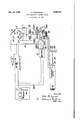
- the single figure is a circuit diagram of a 3 control for regulating the speed of a gas-tin bine power-plant by varying the quantity of fuel passing thereto.
- the compressor 3 of the power-plant 8 is directly coupled to an alternator l so that the speed of the latter is proportional to the speed of the former.
- the frequency of the current generated by the alternator is directly related to the speed of the compressor.
- the output of the alternator is conveyed by conductors II to a polarised relay i2 whose armature I3 is thereby made to vibrate alternately to engage a pair of contacts II, it.
- a condenser IB is charged from a source of direct current I! which is applied to the input points of a Maxwell bridge-network, the current source l1 being connected with these points by conductors IS.
- the Maxwell bridge-network comprises three arms having the resistances I9, 20 and 2i inserted therein and a condenser arm having the condenser l inserted therein.
- the input points of the bridge-network are shown at a and b whilst the output points are at c and d.
- the source of direct current I! be a rectifier which is supplied with alternating current from the compressor-driven alternator ll through conductors 22.
- the output points 0 and d of the bridge-network are connected through a low pass-filter of known form diagrammatically indicated by the box 23 which encloses the components of the filter and to a load resistance 24a, 24b associated with an amplifier unit.
- the function of the lowpass filter 23 is to eliminate the pulsations in the current delivered from the bridge-network so that these pulsations are not applied to the load resistance 24a, la-as would otherwise be the case whether the bridge was balanced or not.
- the potential-difference prevailing across the load-resistance is proportional to the net current flowing from one output point of the bridge-network to the other. cated above, is proportional to the difference between the prevailing frequency with which the condenser is being charged and discharged and the frequency with which it should be charged and discharged in order to produce balance of the bridge.
- the amplifier unit which is generally indicated as a whole by the box 25 incorporates a pair of thermionic valves 26, the control grids 21 of which are connected by conductors 28 to one end of the load-resistance 24a, 24b while the cathodes 29 of the valves are both connected to the centre point of the load-resistance by a conductor 30.
- associated with each valve is placed between the cathode 29 and the common connection 30 to the load-resistance 24a, 24b.
- the anodes 32 of the valve are respectively connected to one end of the coil of a polarised relay 33 and the high-tension supply for the amplifier unit is fed in at points 34, one of which connects to the centre point of the coil of the polarised relay.
- the high-tension supply may be obtained as shown in Figure 1 from the unit H, the low-tension supply being provided by a battery 40 in known manner.
- the polarised relay 33 controls the operation and direction of rotation of a reversible electric motor 35 which is driven from a battery ii.
- the motor is connected to a valve 36 as at 39 and is This, as indi- I capable of adjusting the setting of the valve which regulates the quantity of fuel passing from a pump 31, to the power-plant by a pipe I8.
- the motor 35 may be connected with the valve 33 through a worm and worm-wheel drive and a linkage which connects the worm-wheel with the valve.
- the electric motor 35 may be provided with a split field-winding and there is preferably associated with it an automatic brake and clutch of known construction in order to prevent hunting of the apparatus.
- the frequency with which the condenser I8 is charged and discharged in order to produce balance in the Maxwell bridge-network is arbitrarily determined by the values for the capacity of the condenser i6 and for the resistances I3, 30 and ii. Since this frequency depends upon the frequency of the current generated by the compressor-driven alternator l0 (and hence on the speed of the power-plant) the condenser and resistances are selected to produce balance in the bridge-network at a preselected datum speed of the power-plant.
- the condenser I3 When the power-plant departs from the datum speed value the condenser I3 is charged and discharged with a frequency greater or less than that required to maintain balance of the Maxwell bridge-network. Accordingly a steady potentialdilference is produced across the load-resistance 2hr, 24b and one or the other of the thermionic valves 23a, 26b passes a greater current than is passed by the other.
- the current from the amplifier unit 23 energises the polarised relay 33 associated therewith in one sense or the other to fuel-valve 36. The latter will be moved to increase or decrease the quantity of fuel passing to the power-plant depending upon whether the latter has decreased or increased its speed relative to the datum value. As a consequence the datum speed will be re-established.
- the datum speed range By providing a resistance 52 of fixed value in series with the adjustable resistance U (in which case the resistance arm comprises said two resistances) it is possible for the datum speed range to be made effective where desired within a wide range of power-plant speeds. That is the reuse of control effected by the adjustable resistance 2
- the adjustable resistance 2! may produce a speed adjustment of 1000 R. P. M. and thlsmay take place at any point between a speed range of 10,000 to 20,000 R. P. M. (say as l213,000 R. P. M. or l118,000 R. P. M.) depending upon the value of the fixed resistance.
- a device for governing the speed of a gasturbine engine comprising a bridge network having three resistance arms and a condenser arm. a current source from which the condenser is charged, a source of direct current applied to the input points of the network, means driven by the engine for alternately connecting the current source with the condenser to charge the condenser and for discharging the condenser, the resistances of the resistance arms and the capacity of the condenser being selected so that the bridge network is balanced when the engine speed is at a datum value, electronic response and actuating means connected with the output points of the network and operated by current from the bridge when the latter is unbalanced following on a departure of the engine speed from said datum value, relay means actuated by the electronic response and actuating means,
- engine-speed regulating means actuated by said electronic means to return the engine speed to said datum value and thereby to re-establish balance in the bridge network and means for vary- 'ing the resistance value of an arm of the net- 7 work so that the datum value of engine speed at which the network is balanced is variable.
- the resistance arm having the variable resistance comprises a changeable, non-variable resistanceand a variable resistance in series therewith.
Landscapes
- Engineering & Computer Science (AREA)
- Power Engineering (AREA)
- Control Of Direct Current Motors (AREA)
Description
Dec. 27, 1949 P. FORTESCUE SPEED RESPONSIVE CONTROL SYSTEM Filed Sept. 13, 1945 MN Q QWN Patented Dec. 27, 1949 SPEED RESPONSIVE CONTROL SYSTEM Peter Fortescue, Bristol, England, assignor to The Bristol Aeroplane Company Limited, Bristol, England, a British company Application September 13, 1945, Serial No. 616,030 In Great Britain July 3, 1944 Section 1, Public Law 690, August 8, 1948 Patent expires July 3, 1964 2 Claims.
This invention concerns improvements in or relating to speed governing or temperature regulating.
It is desirable to govern the speed of certain apparatus with great precision by means which is unaffected by changes in the intrinsic characteristics of the components since this obviates the necessity of periodically making compensating adjustments.
It is an object of the present invention to provide speed governing means that satisfies these requirements.
The present invention makes use of a known method for accurately determining the capacity of a condenser which is due to Clerk Maxwell. The condenser whose capacity is to be measured is substituted for one arm of a Wheatstone bridge-network. A commutator is also connected in this arm by means of which the condenser is alternately charged and discharged. The commutator is driven by an electric motor, supplied from a steady source, and whose speed can be varied as required. The charging current is applied to the bridge-network from a battery in the same way as for a Wheatstone bridge.
With this arrangement the galvanometer is aiiected by a constant current which flows along the galvanometer branch in one direction and by a series of current impulses which flow along the branch in the opposite direction. These pulsations are produced in the network by the condenser being alternately charged and discharged. When the bridge-network is balanced, the steady current and the mean value of the impulses are equal (that is the net current flow in the galvanometer branch is zero) so that if the impulse frequency is suificiently high and the galvanometer has a linear response it will not be deflected. When the bridge-network is unbalanced, however, the galvanometer will defleet to an extent proportional to the difference between the steady current and the mean value of the current impulses, that is, to an extent proportional to the net current flow in the galvanometer branch.
The condition for zero deflection, or balance, was given by Maxwell as:
where C is the condenser capacity, P, Q, R, are the resistances of the arms of the Wheatstone bridge, and 11b is the frequency of the commutator, and S is the resistance of the network.
At any other frequency 11; the next galvanometer current is:
where K is a constant dependent only upon the circuit constants.
It will be clear therefore that the net galvanometer current at m is zero and that at any other value n; it is i l. The value of the net galvanometer current is therefore solely dependent upon the frequency of the commutator. Moreover the range of the galvanometer deflections may be arbitrarily selected to indicate any desired range of frequency 1th to m in which m is greater or less than m.
A description of this method with a diagram of the bridge-network is to be found on pages 59-60 of Electrical Measurements and Measuring Instruments by E. W. Golding (3rd edition, 1942, by Sir Isaac Pitman & Sons Ltd.)
Hereinafter throughout the specification the modified Wheatstone bridge described above comprising the three resistance arms, the condenser arm and the commutator associated therewith will be referred to as a Maxwell bridge-network." Furthermore the points of the network across which the galvanometer would normally be connected will be referred to as the "output points of the network, although during balance of the bridge there is no net current flow from one to the other of said points.
According to one aspect of the present invention a method of speed-governing is characterised in that a source of direct current is adapted to be applied to a Maxwell bridge-network the condenser of which is alternately charged therefrom and discharged with a frequency proportional to the speed to be governed, and the output points of the network are connected to electrical means which is brought into operation upon a difference between the value of the steady current and the mean value of the current impulses being established consequent upon the speed to be governed departing. from a datum value corresponding to a state of balance in the bridge, said means being effective automatically to adjust the speed to be governed to restore the datum value thereof and re-establish balance in the bridge-network.
A specific embodiment of the present invention will now be described by way of example with reference to the accompanying drawings whereof:
The single figure is a circuit diagram of a 3 control for regulating the speed of a gas-tin bine power-plant by varying the quantity of fuel passing thereto.
Referring to the figure: the compressor 3 of the power-plant 8 is directly coupled to an alternator l so that the speed of the latter is proportional to the speed of the former. As a consequence the frequency of the current generated by the alternator is directly related to the speed of the compressor. The output of the alternator is conveyed by conductors II to a polarised relay i2 whose armature I3 is thereby made to vibrate alternately to engage a pair of contacts II, it. When the armature i3 engages contact I! a condenser IB is charged from a source of direct current I! which is applied to the input points of a Maxwell bridge-network, the current source l1 being connected with these points by conductors IS. The Maxwell bridge-network comprises three arms having the resistances I9, 20 and 2i inserted therein and a condenser arm having the condenser l inserted therein. The input points of the bridge-network are shown at a and b whilst the output points are at c and d. As indicated, when armature l3 engages contact I5 condenser 16 is charged from source l'I-when armature l3 engages contact I 4 the condenser is discharged. It is preferred that the source of direct current I! be a rectifier which is supplied with alternating current from the compressor-driven alternator ll through conductors 22.
The output points 0 and d of the bridge-network are connected through a low pass-filter of known form diagrammatically indicated by the box 23 which encloses the components of the filter and to a load resistance 24a, 24b associated with an amplifier unit. The function of the lowpass filter 23 is to eliminate the pulsations in the current delivered from the bridge-network so that these pulsations are not applied to the load resistance 24a, la-as would otherwise be the case whether the bridge was balanced or not. As a consequence the potential-difference prevailing across the load-resistance is proportional to the net current flowing from one output point of the bridge-network to the other. cated above, is proportional to the difference between the prevailing frequency with which the condenser is being charged and discharged and the frequency with which it should be charged and discharged in order to produce balance of the bridge.
The amplifier unit which is generally indicated as a whole by the box 25 incorporates a pair of thermionic valves 26, the control grids 21 of which are connected by conductors 28 to one end of the load-resistance 24a, 24b while the cathodes 29 of the valves are both connected to the centre point of the load-resistance by a conductor 30. The self-biasing resistance 3| associated with each valve is placed between the cathode 29 and the common connection 30 to the load-resistance 24a, 24b. The anodes 32 of the valve are respectively connected to one end of the coil of a polarised relay 33 and the high-tension supply for the amplifier unit is fed in at points 34, one of which connects to the centre point of the coil of the polarised relay. The high-tension supply may be obtained as shown in Figure 1 from the unit H, the low-tension supply being provided by a battery 40 in known manner.
The polarised relay 33 controls the operation and direction of rotation of a reversible electric motor 35 which is driven from a battery ii. The motor is connected to a valve 36 as at 39 and is This, as indi- I capable of adjusting the setting of the valve which regulates the quantity of fuel passing from a pump 31, to the power-plant by a pipe I8. For instance the motor 35 may be connected with the valve 33 through a worm and worm-wheel drive and a linkage which connects the worm-wheel with the valve. The electric motor 35 may be provided with a split field-winding and there is preferably associated with it an automatic brake and clutch of known construction in order to prevent hunting of the apparatus.
As has been indicated in the opening paragraphs of the specification, the frequency with which the condenser I8 is charged and discharged in order to produce balance in the Maxwell bridge-network is arbitrarily determined by the values for the capacity of the condenser i6 and for the resistances I3, 30 and ii. Since this frequency depends upon the frequency of the current generated by the compressor-driven alternator l0 (and hence on the speed of the power-plant) the condenser and resistances are selected to produce balance in the bridge-network at a preselected datum speed of the power-plant.
Whilst this datum speed is maintained by the power-plant the bridge-network is balanced, there is therefore no potential difference across the load resistance 24, and the amplifier unit 25 is inoperative. Consequently the polarised relay 33 associated with said unit remains open so that the fuel-valve-setting motor I! is inoperative. The setting of the fuel-valve 33 is then such that the quantity of fuel passing to the power-plant will maintain the latter at the datum speed value.
When the power-plant departs from the datum speed value the condenser I3 is charged and discharged with a frequency greater or less than that required to maintain balance of the Maxwell bridge-network. Accordingly a steady potentialdilference is produced across the load-resistance 2hr, 24b and one or the other of the thermionic valves 23a, 26b passes a greater current than is passed by the other. The current from the amplifier unit 23 energises the polarised relay 33 associated therewith in one sense or the other to fuel-valve 36. The latter will be moved to increase or decrease the quantity of fuel passing to the power-plant depending upon whether the latter has decreased or increased its speed relative to the datum value. As a consequence the datum speed will be re-established.
It is desirable not only to be able to maintain the power-plant automatically at a datum speed as described above but to be capable of varying the value of the datum speed at which the power plane is automatically maintained. This is provided for by varying the value of the resistance 2! of the bridge-network. By adjusting the value of this resistance the frequency with which the condenser l6 should be charged and discharged in order to maintain balance in the bridge-network is altered. The speed of the power-plant 7 is therefore changed by the fuel-valve-setting motor 35 adjusting the fuel-valve 36 as described above so that the newly selected datum speed is established. At this speed the condenser IE will be charged and discharged with a frequency which produces balance of the bridge network.
By providing a resistance 52 of fixed value in series with the adjustable resistance U (in which case the resistance arm comprises said two resistances) it is possible for the datum speed range to be made effective where desired within a wide range of power-plant speeds. That is the reuse of control effected by the adjustable resistance 2| may be applied between any two prescribed speeds of operation of the power-plant by a suitable selection for the value of the fixed resistance 52. For instance, the adjustable resistance 2! may produce a speed adjustment of 1000 R. P. M. and thlsmay take place at any point between a speed range of 10,000 to 20,000 R. P. M. (say as l213,000 R. P. M. or l118,000 R. P. M.) depending upon the value of the fixed resistance.
I claim:
1. A device for governing the speed of a gasturbine engine comprising a bridge network having three resistance arms and a condenser arm. a current source from which the condenser is charged, a source of direct current applied to the input points of the network, means driven by the engine for alternately connecting the current source with the condenser to charge the condenser and for discharging the condenser, the resistances of the resistance arms and the capacity of the condenser being selected so that the bridge network is balanced when the engine speed is at a datum value, electronic response and actuating means connected with the output points of the network and operated by current from the bridge when the latter is unbalanced following on a departure of the engine speed from said datum value, relay means actuated by the electronic response and actuating means,
assume 6 engine-speed regulating means actuated by said electronic means to return the engine speed to said datum value and thereby to re-establish balance in the bridge network and means for vary- 'ing the resistance value of an arm of the net- 7 work so that the datum value of engine speed at which the network is balanced is variable.
2. A device according to claim 1 in which the resistance arm having the variable resistance comprises a changeable, non-variable resistanceand a variable resistance in series therewith.
' PETER FORTESCUE.
REFERENCES CITED The iollowing references are of record in the file of this patent:
UNITED STATES PATENTS
Applications Claiming Priority (1)
| Application Number | Priority Date | Filing Date | Title |
|---|---|---|---|
| GB2492472X | 1944-07-03 |
Publications (1)
| Publication Number | Publication Date |
|---|---|
| US2492472A true US2492472A (en) | 1949-12-27 |
Family
ID=10908296
Family Applications (1)
| Application Number | Title | Priority Date | Filing Date |
|---|---|---|---|
| US616030A Expired - Lifetime US2492472A (en) | 1944-07-03 | 1945-09-13 | Speed responsive control system |
Country Status (1)
| Country | Link |
|---|---|
| US (1) | US2492472A (en) |
Cited By (20)
| Publication number | Priority date | Publication date | Assignee | Title |
|---|---|---|---|---|
| US2638992A (en) * | 1946-07-12 | 1953-05-19 | Curtiss Wright Corp | Gas turbine power control |
| US2648194A (en) * | 1949-02-09 | 1953-08-11 | Gen Motors Corp | Jet engine fuel controller |
| US2662372A (en) * | 1947-08-27 | 1953-12-15 | Franklin F Offner | Electronic engine speed control system |
| US2667228A (en) * | 1949-02-24 | 1954-01-26 | Cyrus F Wood | Aircraft fuel and propeller pitch control |
| US2697908A (en) * | 1949-03-31 | 1954-12-28 | Franklin F Offner | System for accelerating engines to selected speeds and maintaining the speed selected |
| US2734340A (en) * | 1954-07-13 | 1956-02-14 | Jet engine power regulator | |
| US2741086A (en) * | 1950-04-26 | 1956-04-10 | Bendix Aviat Corp | Automatic starter control |
| US2748603A (en) * | 1950-05-31 | 1956-06-05 | Wilcox Roy Milton | Balancing machine |
| US2760337A (en) * | 1950-04-21 | 1956-08-28 | Honeywell Regulator Co | Jet engine fuel control apparatus |
| US2805542A (en) * | 1950-11-04 | 1957-09-10 | Westinghouse Electric Corp | Speed and temperature responsive control for jet engine nozzle and fuel supply |
| US2827910A (en) * | 1951-12-29 | 1958-03-25 | Gen Electric | Electrical speed control system for engines |
| US2857150A (en) * | 1953-06-19 | 1958-10-21 | Shell Dev | Centrifugal pump for control systems and method of establishing a fluid pressure |
| US2963861A (en) * | 1947-12-18 | 1960-12-13 | Bendix Corp | Electronic fuel control apparatus for an engine |
| US2971335A (en) * | 1948-07-27 | 1961-02-14 | Bendix Corp | Speed and temperature responsive fuel control system for combustion engines |
| US2972103A (en) * | 1957-10-31 | 1961-02-14 | Ind Instr Inc | Portable recording instrument |
| US3021891A (en) * | 1956-02-24 | 1962-02-20 | Bendix Corp | Acceleration limiting device for use with hydro-mechanical fuel metering systems |
| US3028526A (en) * | 1956-08-03 | 1962-04-03 | Bendix Corp | Reactance-type frequency sensitive bridge for speed sensor network |
| US3046450A (en) * | 1959-07-09 | 1962-07-24 | United Aircraft Corp | Speed responsive fuel control for helicopters |
| US3192382A (en) * | 1961-07-24 | 1965-06-29 | Westinghouse Air Brake Co | Automatic vehicle control apparatus |
| US3422619A (en) * | 1966-06-06 | 1969-01-21 | Garrett Corp | Electronic controls for high-speed machinery |
Citations (8)
| Publication number | Priority date | Publication date | Assignee | Title |
|---|---|---|---|---|
| DE380586C (en) * | 1923-09-10 | Radio Electr Soc Fr | Electric speed regulator, especially for drive motors for electrical machines | |
| US1604163A (en) * | 1923-09-05 | 1926-10-26 | American Telephone & Telegraph | Means for regulating motors |
| US1611223A (en) * | 1923-12-19 | 1926-12-21 | American Telephone & Telegraph | Apparatus for controlling the frequency of an alternating current |
| US1833048A (en) * | 1930-11-11 | 1931-11-24 | Henry H Cutler | Speed control system |
| US2124725A (en) * | 1935-06-19 | 1938-07-26 | Leeds & Northrup Co | Electrical generating system |
| US2151127A (en) * | 1936-02-27 | 1939-03-21 | Southern States Equipment Co | Electrical control |
| US2275317A (en) * | 1939-01-17 | 1942-03-03 | Bailey Meter Co | Measuring and controlling apparatus |
| US2431501A (en) * | 1944-12-21 | 1947-11-25 | Leeds & Northrup Co | Frequency control system |
-
1945
- 1945-09-13 US US616030A patent/US2492472A/en not_active Expired - Lifetime
Patent Citations (8)
| Publication number | Priority date | Publication date | Assignee | Title |
|---|---|---|---|---|
| DE380586C (en) * | 1923-09-10 | Radio Electr Soc Fr | Electric speed regulator, especially for drive motors for electrical machines | |
| US1604163A (en) * | 1923-09-05 | 1926-10-26 | American Telephone & Telegraph | Means for regulating motors |
| US1611223A (en) * | 1923-12-19 | 1926-12-21 | American Telephone & Telegraph | Apparatus for controlling the frequency of an alternating current |
| US1833048A (en) * | 1930-11-11 | 1931-11-24 | Henry H Cutler | Speed control system |
| US2124725A (en) * | 1935-06-19 | 1938-07-26 | Leeds & Northrup Co | Electrical generating system |
| US2151127A (en) * | 1936-02-27 | 1939-03-21 | Southern States Equipment Co | Electrical control |
| US2275317A (en) * | 1939-01-17 | 1942-03-03 | Bailey Meter Co | Measuring and controlling apparatus |
| US2431501A (en) * | 1944-12-21 | 1947-11-25 | Leeds & Northrup Co | Frequency control system |
Cited By (20)
| Publication number | Priority date | Publication date | Assignee | Title |
|---|---|---|---|---|
| US2638992A (en) * | 1946-07-12 | 1953-05-19 | Curtiss Wright Corp | Gas turbine power control |
| US2662372A (en) * | 1947-08-27 | 1953-12-15 | Franklin F Offner | Electronic engine speed control system |
| US2963861A (en) * | 1947-12-18 | 1960-12-13 | Bendix Corp | Electronic fuel control apparatus for an engine |
| US2971335A (en) * | 1948-07-27 | 1961-02-14 | Bendix Corp | Speed and temperature responsive fuel control system for combustion engines |
| US2648194A (en) * | 1949-02-09 | 1953-08-11 | Gen Motors Corp | Jet engine fuel controller |
| US2667228A (en) * | 1949-02-24 | 1954-01-26 | Cyrus F Wood | Aircraft fuel and propeller pitch control |
| US2697908A (en) * | 1949-03-31 | 1954-12-28 | Franklin F Offner | System for accelerating engines to selected speeds and maintaining the speed selected |
| US2760337A (en) * | 1950-04-21 | 1956-08-28 | Honeywell Regulator Co | Jet engine fuel control apparatus |
| US2741086A (en) * | 1950-04-26 | 1956-04-10 | Bendix Aviat Corp | Automatic starter control |
| US2748603A (en) * | 1950-05-31 | 1956-06-05 | Wilcox Roy Milton | Balancing machine |
| US2805542A (en) * | 1950-11-04 | 1957-09-10 | Westinghouse Electric Corp | Speed and temperature responsive control for jet engine nozzle and fuel supply |
| US2827910A (en) * | 1951-12-29 | 1958-03-25 | Gen Electric | Electrical speed control system for engines |
| US2857150A (en) * | 1953-06-19 | 1958-10-21 | Shell Dev | Centrifugal pump for control systems and method of establishing a fluid pressure |
| US2734340A (en) * | 1954-07-13 | 1956-02-14 | Jet engine power regulator | |
| US3021891A (en) * | 1956-02-24 | 1962-02-20 | Bendix Corp | Acceleration limiting device for use with hydro-mechanical fuel metering systems |
| US3028526A (en) * | 1956-08-03 | 1962-04-03 | Bendix Corp | Reactance-type frequency sensitive bridge for speed sensor network |
| US2972103A (en) * | 1957-10-31 | 1961-02-14 | Ind Instr Inc | Portable recording instrument |
| US3046450A (en) * | 1959-07-09 | 1962-07-24 | United Aircraft Corp | Speed responsive fuel control for helicopters |
| US3192382A (en) * | 1961-07-24 | 1965-06-29 | Westinghouse Air Brake Co | Automatic vehicle control apparatus |
| US3422619A (en) * | 1966-06-06 | 1969-01-21 | Garrett Corp | Electronic controls for high-speed machinery |
Similar Documents
| Publication | Publication Date | Title |
|---|---|---|
| US2492472A (en) | Speed responsive control system | |
| US2300742A (en) | Measuring and control apparatus | |
| US2408451A (en) | Speed control system | |
| US2558729A (en) | Frequency control system | |
| US2376599A (en) | Measuring and controlling apparatus | |
| US2209369A (en) | Measuring and control apparatus | |
| US2593950A (en) | Motor control system | |
| US2376421A (en) | Method and apparatus for producing alternating current of precisely controlled frequency | |
| US3364736A (en) | Hydraulic dynamometers of the hydrokinetic type | |
| US2192022A (en) | Measuring and control apparatus | |
| US2263497A (en) | Measuring and control apparatus | |
| US2830245A (en) | Rate and reset rebalanceable control system | |
| US2385481A (en) | Measuring and controlling apparatus | |
| US2446153A (en) | Recalibrating motor control system | |
| US2475576A (en) | Motor control system with stray signal elimination | |
| US2790090A (en) | Displacement sensing system for power plant control | |
| US2383306A (en) | Phase-responsive governor system | |
| US2760337A (en) | Jet engine fuel control apparatus | |
| US2300960A (en) | Dynamometer control system | |
| US2489999A (en) | Recalibrating motor control system | |
| US2508640A (en) | Electric motor control apparatus with feedback antihunting means | |
| US2743097A (en) | Generator loading rate control | |
| US2449476A (en) | Antihunt electrical servomotor system | |
| US2541666A (en) | Control system | |
| US2692359A (en) | Measuring and controlling apparatus |