US2492461A - Corrected schmidt type optical system - Google Patents
Corrected schmidt type optical system Download PDFInfo
- Publication number
- US2492461A US2492461A US635683A US63568345A US2492461A US 2492461 A US2492461 A US 2492461A US 635683 A US635683 A US 635683A US 63568345 A US63568345 A US 63568345A US 2492461 A US2492461 A US 2492461A
- Authority
- US
- United States
- Prior art keywords
- mirror
- curvature
- optical system
- spherical
- correcting
- Prior art date
- Legal status (The legal status is an assumption and is not a legal conclusion. Google has not performed a legal analysis and makes no representation as to the accuracy of the status listed.)
- Expired - Lifetime
Links
- 230000003287 optical effect Effects 0.000 title description 48
- 230000005499 meniscus Effects 0.000 description 26
- 230000004075 alteration Effects 0.000 description 20
- 238000010276 construction Methods 0.000 description 8
- 201000009310 astigmatism Diseases 0.000 description 3
- 239000011521 glass Substances 0.000 description 3
- 238000000034 method Methods 0.000 description 3
- 206010073261 Ovarian theca cell tumour Diseases 0.000 description 2
- 208000001644 thecoma Diseases 0.000 description 2
- 230000004304 visual acuity Effects 0.000 description 2
- 206010010071 Coma Diseases 0.000 description 1
- DGAQECJNVWCQMB-PUAWFVPOSA-M Ilexoside XXIX Chemical compound C[C@@H]1CC[C@@]2(CC[C@@]3(C(=CC[C@H]4[C@]3(CC[C@@H]5[C@@]4(CC[C@@H](C5(C)C)OS(=O)(=O)[O-])C)C)[C@@H]2[C@]1(C)O)C)C(=O)O[C@H]6[C@@H]([C@H]([C@@H]([C@H](O6)CO)O)O)O.[Na+] DGAQECJNVWCQMB-PUAWFVPOSA-M 0.000 description 1
- 230000015572 biosynthetic process Effects 0.000 description 1
- 229910052708 sodium Inorganic materials 0.000 description 1
- 239000011734 sodium Substances 0.000 description 1
Images
Classifications
-
- G—PHYSICS
- G02—OPTICS
- G02B—OPTICAL ELEMENTS, SYSTEMS OR APPARATUS
- G02B17/00—Systems with reflecting surfaces, with or without refracting elements
- G02B17/08—Catadioptric systems
- G02B17/0884—Catadioptric systems having a pupil corrector
-
- G—PHYSICS
- G02—OPTICS
- G02B—OPTICAL ELEMENTS, SYSTEMS OR APPARATUS
- G02B17/00—Systems with reflecting surfaces, with or without refracting elements
- G02B17/08—Catadioptric systems
Definitions
- the simplest form of a mirror system is the spherical mirror which generally has spherical aberration by which the mirror is rendered unserviceable even with small relative apertures.
- Schmidt has succeeded in making a, considerable progress by locating in the center of curvature of a spherical mirror a correcting element by which spherical aberration and astigmatism of the image is avoided. In this way Schmidt succeeded in attaining a field of about 19 with a relative aperture of about 121.4.
- the introduction of the correcting element involves chromatic aberration which, however, is small and can be rendered ineffective by means of a, method devised by Schmidt himself.
- One drawback of the Schmidt system consists in the technical difllculty of making the correcting element, whose surface has a curve of the fourth degree as a meridian section. Moreover, the size of the eld is not sufllcient for many purposes.
- the present invention relates to an optical system' comprising a spherical mirror and a correcting element.
- an optical system' comprising a spherical mirror and a correcting element.
- the correcting element is curved similarly to the mirror and located between the center of curvature of the mirror and the mirror and is traversed only once by the rays partaking in forming the image exhibits the feature that the correcting element has spherical limiting surfaces and the character of a weak negative meniscus lens. It is advisable that the correcting element should be closer to the focal point of the mirror than to the mirror and the center of curvature of the mirror.
- Another form' of construction of the optical system according to the invention exhibits the feature that the correcting element has spherical limiting surfaces and the character oi' a weak negative meniscus lens which is curved in a manner opposite to that of the mirror, which element is located at a distance from the mirror which is larger than the radius of curvature of this mirror and preferably smaller than three times the radius of curvature. It has been found that it is advantageous for the state of correction of the last-mentionedv optical system according to the invention to choose the distance between the mirror and the correcting element larger than 1.25 times the radius of curvature of the mirror. In this case it is simpler to achieve correction for a larger field.
- the diaphragm is preferably located between the correcting element and the mirror.
- the correcting element forming part of the optical system according to the invention has the character of a weak negative meniscus lens.
- the correcting element may consist either of a. single weak negative lens or by a plurality of lenses in such manner that the total strength of the correcting element is small and negative, the two outer surfaces of the correcting element being curved in the same manner.
- the center of curvature of at least one of the surfaces of the correcting element is at the utmost a distance of 1A of the radius of curvature of the mirror from its center of curvature and is preferably located substantially at the center of curvature of the mirror. In this way correction for larger fields can be obtained.
- the centers of curvature of two surfaces of the correcting element in such a manner that they are at the utmost at a distance of 1A of the radius of curvature of the mirror therefrom and preferably 1ocated in the center of curvature of the mirror the field can be still further increased.
- the diaphragm When locating, moreover, the diaphragm in or near the center of curvature of the mirror one obtains an extremely suitable form of construction of the optical systems according to the invention. In fact, the field has an unlimited size in this case, since the coma and the astigmatism of the system have been completely removed.
- the correcting element itself may be achromatised, for instance by constructing it as a cemented doublet both components of which consist of kinds of glass having the same refraction index for the average wavelength of the transmitted light.
- Another method of securing chromatic correction consists in adding to the optical system a weak positive lens which is not bent through or only to a small extent.
- a positive lens between the correcting element and the mirror, preferably in or near the center of curvature of the mirror.
- the distance from the projection surface to the mirror is larger than the distance between the mirror and the correcting element.
- a correcting element having a central aperture as illustrated hereinafter by Example VI. If the said distance corresponds to the distance from the projection surface to the correctlng element then, according to the invention, the radius of curvature of the surface of the correcting element facing the mirror may be made equal to the radius of curvature of the projection surface, as illustrated hereinafter by Example V.
- the surfacemirror may be replaced by a mirror provided at the back with a reflecting layer. at least if the glass layer located in the path of the light rays is thin.
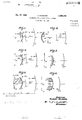
- FIG. 1 is a schematic cross-sectional view of one embodiment of the invention:
- Fig. 2 is a schematic cross-sectional view of another embodiment of the invention in which the diaphragm is located at the center of curvature of the mirror and the miniscus correcting element is closer to the focal surface than to the center of curvature of the mirror:
- Fig. 3 is a schematic cross-sectional view of another embodiment of the invention wherein a plano-convex positive lens is placed at the center of curvature of the mirror:
- Fig. 4 is a schematic cross-sectional view in which the meniscus correcting element is located farther distant from the spherical mirror than the center of curvature thereof;
- Fig. 5 is a schematic cross-sectional view of an embodiment in which a single element serves as the spherical-aberration correcting element for an image receiving element;
- Fig. 6 illustrates an embodiment in which the spherical-aberration correcting element may have a central aperture.
- the resolving power amounts to 0.02% of the focal distance.
- the refracting or reflecting surfaces are numbered i. 2, and so on.
- the radia of curvature are represented by y.
- a positive sign signifies that the surface in question turns its convex side to the direction of the incident light a negative sign signifying that it turns its convex side to this direction.
- the refractive index for sodium light of the glass of all lenses in these three examples is 1.52.
- D represents the diaphragm
- C the correcting element
- S the mirror
- M the center of curvature of the mirror
- F the film support.
- the relative aperture may be increased to 1:0.95 if a resolving power of 0.04% of the focal distance is enough.
- An optical system comprising a concave spherical mirror, and a refractive sphericalaberration correcting meniscus element substantially correcting by refraction the spherical aberration introduced in the optical system by said mirror, said element being positioned to be traversed only once by light rays entering the system and said element having substantially spherical refractive surfaces, one of said surfaces having its center of curvature substantially coincident with the center of curvature of said mirror.
- An optical system comprising a concave spherical mirror, and a refractive spherical-aberration correcting meniscus element substantially correcting by refraction the spherical aberration introduced in the optical system by said mirror.
- said element being positioned to be traversed only once by light rays entering the system and said element having substantially spherical refractive surfaces, said surfaces having their centers of curvature substantially coincident with the center of curvature of said mirror.
- An optical system comprising a concave spherical mirror, and a refractive spherical-aberration correcting meniscus element concave in the same sense as said mirror and positioned between said mirror and the center of curvature of said mirror to be traversed only once by light rays coincident on the system, said element substantially correcting by refraction the spherical aberration introduced in the optical system by said mirror, each refractive surface of said correcting element being spherical.
- An optical system comprising a concave spherical mirror and a refractive spherical-aberration correcting meniscus element concave in the same sense as said mirror and substantially correcting by refraction the spherical aberration introduced in the optical system by said mirror, said element being positioned between said mirror and the center of curvature of said mirror to be traversed only once by light rays incident on the system and having spherical refractive surfaces, said surfaces having their centers of curvature not farther distant from the center of curvature of said mirror than one-fourth the radius of curvature of said mirror.
- An optical system comprising a concave spherical mirror, and a refractive spherical-aberration correcting meniscus element concave in the same sense as said mirror and substantially correcting by refraction the spherical aberration introduced in the optical system by said mirror, said element being positioned between said mirror and the center of curvature of said mirror to be traversed only once by light rays incident on the system and having spherical refractive surfaces, said surfaces having their centers. of curvature substantially coincident with the center of curvature of said mirror.
- An optical system comprising a concave spherical mirror having a radius of curvature r, and a refractive spherical-aberration correcting meniscus element substantially correcting by refraction the spherical aberration introduced in the optical system by said mirror, said element having the character of a weak negative meniscus lens concave in the same sense as said mirror and being positioned to be traversed only once by light rays incident on the system and being spaced a distance d from said mirror, said distance d substantially satisfying the following inequality:
- said element having a spherical refractive surface, said surface having its center of curvature not greater distance from the center of curvature of said mirror than one-fourth r.
- An optical system comprising a. concave spherical mirror having a radius of curvature r, and a refractive spherical-aberration correcting meniscus element substantially correcting by refraction the spherical aberration introduced in the optical system by said mirror, said element having the character of a weak negative meniscus lens concave in the same sense as said mirror and being positioned to be traversed only once by light rays incident on the system and being spaced a distance d from said mirror, said distance d substantially satisfying the following inequality:
- element having the character of a weak negative meniscus lens, and positioned to be traversed only once by light rays incident on the system and interposed between said mirror and the center of curvature thereof, said element having spherical refractive surfaces the centers of curvature of which are substantially coincident with the center of curvature of said mirror, and sto ositioned farther distant from said mirror than said element.
- An optical system comprising a concave spherical mirror, a refractive correcting element substantially correcting the spherical aberration introduced in said system by said mirror, said element being positioned to be traversed only once by light rays entering the system and having the character of a weak negative meniscus lens and having a spherical refractive surface, said surface having its center of curvature substantially coincident with the center of curvature of said mirror, and a weak positive lens at the center o! curvature of said mirror.
- An optical system comprising a concave spherical mirror, a refractive spherical-aberration correcting element concave in the same sense as said mirror and substantially correcting by refraction the spherical aberration introduced in the optical system by said mirror, said element having the character of a weak negative meniscus lens and interposed between said mirror and the center of curvature thereof to be traversed only once by light rays incident on the system 'and having spherical refractive surfaces. and a weak positive lens at the center of curvature of said mirror.
- An optical system comprising a concave spherical mirror, a refractive spherical-aberration correcting meniscus element concave in the same sense as said mirror substantially correcting by refraction the spherical aberration introduced in the optical system by said mirror, said element having the character of a Weak negative meniscus lens and interposed between said mirror and the center of curvature thereof to be traversed only once by light rays incident on the system, said element having spherical refractive surfaces the centers of curvature of which are substantially coincident with the center of curvature of said mirror, and a weak positive lens placed at the center of curvature of said mirror.
- An optical system comprising a concave spherical mirror, and a refractive sphericalaberration correcting meniscus element substantially correcting by refraction the spherical aberration introduced in the optical system by said mirror, said element having the character of a weak negative meniscus lens concave in a sense opposite to the concavity of said mirror and being positioned to be traversed only once by light rays entering the system and being spaced farther distant from said mirror than the radius of curvature of said mirror.
- An optical system comprising a concave spherical mirror having a radius of curvature r, and a refractive spherical-aberration correcting meniscus element substantially correcting by refraction the spherical aberration introduced in the optical system by said mirror, said element having the character of a weak negative meniscus lens concave in a sense opposite to the concavity yof said mirror and being positioned to be traversed only once by light rays entering the system and being spaced a distance d from said mirror to substantially satisfy the following inequality:
- said element being posi- 5 tioned to be traversed only once by light rays entering the system and having spherical refractive surfaces, the centers of curvature of said surfaces being substantially coincident with the centers of curvature of said mirror.
- An optical system comprising a concave spherical mirror, a refractive spherical-aberration correcting meniscus element substantially correcting by refraction the spherical aberration introduced in the optical system by said mirror, said element having the character of a weak negative meniscus lens concave in a sense opposite to the concavity of said mirror and being positioned to be traversed only once by light rays entering the system and being spaced farther distant from said mirror than the radius of curvature of said mirror, and a sto inter o d between said element and said mirror.
- An optical system comprising a concave spherical mirror, and a meniscus element comprising a zonal refractive spherical-aberration correction portion substantially correcting by refraction the spherical aberration introduced in the optical system by said mirror and a central image receiving portion, said element being concave in the same sense as said mirror and being positioned between said mirror and the center of curvature of said mirror with the image receiving portion of said element substantially coincident with the object surface of said system.
- An optical system comprising a concave spherical mirror, and a refractive sphericalaberration correcting meniscus element substantially correcting by refraction the spherical aberration introduced in the optical system by said mirror, said element being concave in the same sense as said mirror and being positioned between said mirror and the center of curvature of said mirror to be traversed only once by light r rays incident on the system, said element having a central aperture.
Landscapes
- Physics & Mathematics (AREA)
- General Physics & Mathematics (AREA)
- Optics & Photonics (AREA)
- Lenses (AREA)
Description
T l d -2 0 x 2 caw x 2. 7
/lwgwrom -saver' ouwtks 6r i AAM/2527 rroawfr A. BOUWERS CORRECTED SCHMIDT TYPE OPTICAL SYSTEM Patented Dec. 27, 1949 SEARCH ROOM CORRECTED SCHMIDT TYPE OPTICAL SYSTEM Albert Bouwers, Delft, Netherlands, assigner to N. V. Optische Industrie De Oude Delft, Delft,
Netherlands Application December 18, 1945, Serial No. 635,683 In the Netherlands July 7, 1941 Section 1, Public Law 690, August 8, 1946 Patent expires July- 7, 1961 l 17 Claims.
In the course of time various mirror systems for the optical formation of images have come to be known. A great advantage of the use of mirrors is that they are free from chromatic aberrations.
The simplest form of a mirror system is the spherical mirror which generally has spherical aberration by which the mirror is rendered unserviceable even with small relative apertures.
With a parabolical mirror the spherical aberration is exactly obviated, as a result of which the relative aperture can theoretically be given an optional value. Practically, however, one 1s greatly limited in this respect, because the parabolisation technique becomes more difcult as the relative aperture of thev mirror increases. In addition to this drawback the parabolical mirror has the serious drawback of involving coma due to which the ileld is reduced to a few degrees at the utmost. g
Schmidt has succeeded in making a, considerable progress by locating in the center of curvature of a spherical mirror a correcting element by which spherical aberration and astigmatism of the image is avoided. In this way Schmidt succeeded in attaining a field of about 19 with a relative aperture of about 121.4. The introduction of the correcting element involves chromatic aberration which, however, is small and can be rendered ineffective by means of a, method devised by Schmidt himself. One drawback of the Schmidt system consists in the technical difllculty of making the correcting element, whose surface has a curve of the fourth degree as a meridian section. Moreover, the size of the eld is not sufllcient for many purposes.
The present invention relates to an optical system' comprising a spherical mirror and a correcting element. According to the recognition on which the invention is based we have succeeded by simple optical means to obtain an optical system, by means of which a sharp image of a large field can be formed with a high luminous intensity. In fact, we have found that this can be ensured by providing a. suitable correcting element having spherical limiting planes at a suitable distance from the spherical mirror forming part of an optical system.
One form of construction of the optical system according to the invention in which the correcting element is curved similarly to the mirror and located between the center of curvature of the mirror and the mirror and is traversed only once by the rays partaking in forming the image exhibits the feature that the correcting element has spherical limiting surfaces and the character of a weak negative meniscus lens. It is advisable that the correcting element should be closer to the focal point of the mirror than to the mirror and the center of curvature of the mirror.
Another form' of construction of the optical system according to the invention exhibits the feature that the correcting element has spherical limiting surfaces and the character oi' a weak negative meniscus lens which is curved in a manner opposite to that of the mirror, which element is located at a distance from the mirror which is larger than the radius of curvature of this mirror and preferably smaller than three times the radius of curvature. It has been found that it is advantageous for the state of correction of the last-mentionedv optical system according to the invention to choose the distance between the mirror and the correcting element larger than 1.25 times the radius of curvature of the mirror. In this case it is simpler to achieve correction for a larger field.
In the first-mentioned form of construction of the optical system according to the invention it is advantageous to locate the diaphragm at the side of the correcting element remote from the mirror. In this way a suitable positioning is obtained in connection with the correction of the coma and the astigmatism. For the same reason, in the second form of construction of the optical system according to the invention the diaphragm is preferably located between the correcting element and the mirror.
As has already been stated the correcting element forming part of the optical system according to the invention has the character of a weak negative meniscus lens. Thus, for instance, the correcting element may consist either of a. single weak negative lens or by a plurality of lenses in such manner that the total strength of the correcting element is small and negative, the two outer surfaces of the correcting element being curved in the same manner.
In a suitable form of construction of the optical system according to the invention the center of curvature of at least one of the surfaces of the correcting element is at the utmost a distance of 1A of the radius of curvature of the mirror from its center of curvature and is preferably located substantially at the center of curvature of the mirror. In this way correction for larger fields can be obtained. When choosing the centers of curvature of two surfaces of the correcting element in such a manner that they are at the utmost at a distance of 1A of the radius of curvature of the mirror therefrom and preferably 1ocated in the center of curvature of the mirror the field can be still further increased. When locating, moreover, the diaphragm in or near the center of curvature of the mirror one obtains an extremely suitable form of construction of the optical systems according to the invention. In fact, the field has an unlimited size in this case, since the coma and the astigmatism of the system have been completely removed.
For several uses it may be desirable to obviate the small colour error inherent to the correcting element of the optical system according to the invention.
To this end the correcting element itself may be achromatised, for instance by constructing it as a cemented doublet both components of which consist of kinds of glass having the same refraction index for the average wavelength of the transmitted light.
Another method of securing chromatic correction consists in adding to the optical system a weak positive lens which is not bent through or only to a small extent.
According to the invention it is advisable to place a positive lens between the correcting element and the mirror, preferably in or near the center of curvature of the mirror. According to the invention it may be advantageous in some cases to choose the strength of the correcting element and the positive lens as well as their relative distance in such manner that the correcting element and the positive lens have a positive strength.
In the first form of construction of the optical system according to the invention it may occur that the distance from the projection surface to the mirror is larger than the distance between the mirror and the correcting element. In this case, according to the invention use may be made of a correcting element having a central aperture, as illustrated hereinafter by Example VI. If the said distance corresponds to the distance from the projection surface to the correctlng element then, according to the invention, the radius of curvature of the surface of the correcting element facing the mirror may be made equal to the radius of curvature of the projection surface, as illustrated hereinafter by Example V. In order to counteract damaging of the reflecting surface of' the mirror the surfacemirror may be replaced by a mirror provided at the back with a reflecting layer. at least if the glass layer located in the path of the light rays is thin.
The invention will be more fully explained by reference to the accompanying drawing, in which Fig. 1 is a schematic cross-sectional view of one embodiment of the invention:
Fig. 2 is a schematic cross-sectional view of another embodiment of the invention in which the diaphragm is located at the center of curvature of the mirror and the miniscus correcting element is closer to the focal surface than to the center of curvature of the mirror:
Fig. 3 is a schematic cross-sectional view of another embodiment of the invention wherein a plano-convex positive lens is placed at the center of curvature of the mirror:
GII
Fig. 4 is a schematic cross-sectional view in which the meniscus correcting element is located farther distant from the spherical mirror than the center of curvature thereof;
Fig. 5 is a schematic cross-sectional view of an embodiment in which a single element serves as the spherical-aberration correcting element for an image receiving element; and
Fig. 6 illustrates an embodiment in which the spherical-aberration correcting element may have a central aperture.
In the following examples of forms of construction of the optical system according to the invention the resolving power amounts to 0.02% of the focal distance. The refracting or reflecting surfaces are numbered i. 2, and so on. The radia of curvature are represented by y. A positive sign signifies that the surface in question turns its convex side to the direction of the incident light a negative sign signifying that it turns its convex side to this direction.
All measures have been stated in mms.
The refractive index for sodium light of the glass of all lenses in these three examples is 1.52.
In the figures D represents the diaphragm, C the correcting element, S the mirror, M the center of curvature of the mirror and F the film support. 'I'he light enters from the left.
Example 1 (Fig. 1)
[Relative aperture l: 1.2; field N1 Diaphragm Distances In this example one lobtains the advantage of a small length of the camera with respect to the Schmidt camera.
Example II (F19. 2)
[Relative aperture 1: 1.2; eld unlimited] Diaphragm Distansl 4. D fg-47, 3
The relative aperture may be increased to 1:0.95 if a resolving power of 0.04% of the focal distance is enough.
Example III (Fig. 3)
SEARCH ROOM :Massi Example IV (Fig. 4)
[Relative aperture 111.9; neld unlimited] Distances 43 diaphragm What I claim is:
1. An optical system comprising a concave spherical mirror, and a refractive sphericalaberration correcting meniscus element substantially correcting by refraction the spherical aberration introduced in the optical system by said mirror, said element being positioned to be traversed only once by light rays entering the system and said element having substantially spherical refractive surfaces, one of said surfaces having its center of curvature substantially coincident with the center of curvature of said mirror.
2. An optical system comprising a concave spherical mirror, and a refractive spherical-aberration correcting meniscus element substantially correcting by refraction the spherical aberration introduced in the optical system by said mirror. said element being positioned to be traversed only once by light rays entering the system and said element having substantially spherical refractive surfaces, said surfaces having their centers of curvature substantially coincident with the center of curvature of said mirror.
3. An optical system comprising a concave spherical mirror, and a refractive spherical-aberration correcting meniscus element concave in the same sense as said mirror and positioned between said mirror and the center of curvature of said mirror to be traversed only once by light rays coincident on the system, said element substantially correcting by refraction the spherical aberration introduced in the optical system by said mirror, each refractive surface of said correcting element being spherical.
4. An optical system comprising a concave spherical mirror and a refractive spherical-aberration correcting meniscus element concave in the same sense as said mirror and substantially correcting by refraction the spherical aberration introduced in the optical system by said mirror, said element being positioned between said mirror and the center of curvature of said mirror to be traversed only once by light rays incident on the system and having spherical refractive surfaces, said surfaces having their centers of curvature not farther distant from the center of curvature of said mirror than one-fourth the radius of curvature of said mirror.
5. An optical system comprising a concave spherical mirror, and a refractive spherical-aberration correcting meniscus element concave in the same sense as said mirror and substantially correcting by refraction the spherical aberration introduced in the optical system by said mirror, said element being positioned between said mirror and the center of curvature of said mirror to be traversed only once by light rays incident on the system and having spherical refractive surfaces, said surfaces having their centers. of curvature substantially coincident with the center of curvature of said mirror.
6. An optical system comprising a concave spherical mirror having a radius of curvature r, and a refractive spherical-aberration correcting meniscus element substantially correcting by refraction the spherical aberration introduced in the optical system by said mirror, said element having the character of a weak negative meniscus lens concave in the same sense as said mirror and being positioned to be traversed only once by light rays incident on the system and being spaced a distance d from said mirror, said distance d substantially satisfying the following inequality:
said element having a spherical refractive surface, said surface having its center of curvature not greater distance from the center of curvature of said mirror than one-fourth r.
7. An optical system comprising a. concave spherical mirror having a radius of curvature r, and a refractive spherical-aberration correcting meniscus element substantially correcting by refraction the spherical aberration introduced in the optical system by said mirror, said element having the character of a weak negative meniscus lens concave in the same sense as said mirror and being positioned to be traversed only once by light rays incident on the system and being spaced a distance d from said mirror, said distance d substantially satisfying the following inequality:
element having the character of a weak negative meniscus lens, and positioned to be traversed only once by light rays incident on the system and interposed between said mirror and the center of curvature thereof, said element having spherical refractive surfaces the centers of curvature of which are substantially coincident with the center of curvature of said mirror, and sto ositioned farther distant from said mirror than said element.
9. An optical system comprising a concave spherical mirror, a refractive correcting element substantially correcting the spherical aberration introduced in said system by said mirror, said element being positioned to be traversed only once by light rays entering the system and having the character of a weak negative meniscus lens and having a spherical refractive surface, said surface having its center of curvature substantially coincident with the center of curvature of said mirror, and a weak positive lens at the center o! curvature of said mirror.
10. An optical system comprising a concave spherical mirror, a refractive spherical-aberration correcting element concave in the same sense as said mirror and substantially correcting by refraction the spherical aberration introduced in the optical system by said mirror, said element having the character of a weak negative meniscus lens and interposed between said mirror and the center of curvature thereof to be traversed only once by light rays incident on the system 'and having spherical refractive surfaces. and a weak positive lens at the center of curvature of said mirror.
11. An optical system comprising a concave spherical mirror, a refractive spherical-aberration correcting meniscus element concave in the same sense as said mirror substantially correcting by refraction the spherical aberration introduced in the optical system by said mirror, said element having the character of a Weak negative meniscus lens and interposed between said mirror and the center of curvature thereof to be traversed only once by light rays incident on the system, said element having spherical refractive surfaces the centers of curvature of which are substantially coincident with the center of curvature of said mirror, and a weak positive lens placed at the center of curvature of said mirror.
12. An optical system comprising a concave spherical mirror, and a refractive sphericalaberration correcting meniscus element substantially correcting by refraction the spherical aberration introduced in the optical system by said mirror, said element having the character of a weak negative meniscus lens concave in a sense opposite to the concavity of said mirror and being positioned to be traversed only once by light rays entering the system and being spaced farther distant from said mirror than the radius of curvature of said mirror.
13. An optical system comprising a concave spherical mirror having a radius of curvature r, and a refractive spherical-aberration correcting meniscus element substantially correcting by refraction the spherical aberration introduced in the optical system by said mirror, said element having the character of a weak negative meniscus lens concave in a sense opposite to the concavity yof said mirror and being positioned to be traversed only once by light rays entering the system and being spaced a distance d from said mirror to substantially satisfy the following inequality:
system by said mirror, said element being posi- 5 tioned to be traversed only once by light rays entering the system and having spherical refractive surfaces, the centers of curvature of said surfaces being substantially coincident with the centers of curvature of said mirror.
15. An optical system comprising a concave spherical mirror, a refractive spherical-aberration correcting meniscus element substantially correcting by refraction the spherical aberration introduced in the optical system by said mirror, said element having the character of a weak negative meniscus lens concave in a sense opposite to the concavity of said mirror and being positioned to be traversed only once by light rays entering the system and being spaced farther distant from said mirror than the radius of curvature of said mirror, and a sto inter o d between said element and said mirror.
16. An optical system comprising a concave spherical mirror, and a meniscus element comprising a zonal refractive spherical-aberration correction portion substantially correcting by refraction the spherical aberration introduced in the optical system by said mirror and a central image receiving portion, said element being concave in the same sense as said mirror and being positioned between said mirror and the center of curvature of said mirror with the image receiving portion of said element substantially coincident with the object surface of said system.
17. An optical system comprising a concave spherical mirror, and a refractive sphericalaberration correcting meniscus element substantially correcting by refraction the spherical aberration introduced in the optical system by said mirror, said element being concave in the same sense as said mirror and being positioned between said mirror and the center of curvature of said mirror to be traversed only once by light r rays incident on the system, said element having a central aperture.
ALBERT BOUWERS.
REFERENCES CITED The following references are of record in the le of this patent:
UNITED STATES PATENTS OTHER REFERENCES Journal Optical Society of America, vol. 34, No. 5, May 1944, pages 270 to 284. Article by Maksutov. Published by American Institute of Physics, 57 East 55th Street, New York, N. Y.
Applications Claiming Priority (1)
| Application Number | Priority Date | Filing Date | Title |
|---|---|---|---|
| NL2492461X | 1941-07-07 |
Publications (1)
| Publication Number | Publication Date |
|---|---|
| US2492461A true US2492461A (en) | 1949-12-27 |
Family
ID=19874425
Family Applications (1)
| Application Number | Title | Priority Date | Filing Date |
|---|---|---|---|
| US635683A Expired - Lifetime US2492461A (en) | 1941-07-07 | 1945-12-18 | Corrected schmidt type optical system |
Country Status (1)
| Country | Link |
|---|---|
| US (1) | US2492461A (en) |
Cited By (15)
| Publication number | Priority date | Publication date | Assignee | Title |
|---|---|---|---|---|
| US2558593A (en) * | 1949-03-25 | 1951-06-26 | Northrop Aircraft Inc | Reflecting telescope |
| US2608129A (en) * | 1951-03-26 | 1952-08-26 | Northrop Aircraft Inc | Two-mirror telescope focusing system |
| US2642488A (en) * | 1949-01-03 | 1953-06-16 | Rca Corp | Schmidt television projector having meniscus to correct for antihalation lens |
| US2664027A (en) * | 1951-02-07 | 1953-12-29 | Gen Precision Lab Inc | Modified schmidt-type optical system |
| US2726574A (en) * | 1950-09-11 | 1955-12-13 | Leitz Ernst Gmbh | Reflecting mirror and lens objective of the cassegrain type |
| US2749801A (en) * | 1951-11-09 | 1956-06-12 | American Optical Corp | Reflective optical projection systems |
| US2793564A (en) * | 1952-04-29 | 1957-05-28 | Optische Ind De Oude Delft Nv | Optical image forming lens and mirror system comprising a spherical mirror and two meniscus corrector lenses |
| US2821107A (en) * | 1952-09-12 | 1958-01-28 | Optische Ind De Oude Delft Nv | Optical mirror system comprising at least one conic lens corrector element |
| US3001446A (en) * | 1951-10-15 | 1961-09-26 | Optische Ind De Oude Delft Nv | Optical systems comprising a spherical concave mirror and a meniscus lens |
| US3049054A (en) * | 1957-11-26 | 1962-08-14 | Waland Robert Louis | Astronomical cameras and optical systems therefor |
| US3051049A (en) * | 1959-03-02 | 1962-08-28 | Bell & Howell Co | Catadioptric objective |
| US3689132A (en) * | 1970-06-29 | 1972-09-05 | Polaroid Corp | Panoramic optical system |
| US4234240A (en) * | 1976-02-02 | 1980-11-18 | The Rank Organization Limited | Optical scanning system with unwanted reflections controlled |
| US4600270A (en) * | 1984-04-25 | 1986-07-15 | The United States Of America As Represented By The Secretary Of The Air Force | Beam recombination via cylindrical mirror |
| US6560039B1 (en) | 1999-09-28 | 2003-05-06 | Tropel Corporation | Double mirror catadioptric objective lens system with three optical surface multifunction component |
Citations (5)
| Publication number | Priority date | Publication date | Assignee | Title |
|---|---|---|---|---|
| US2141884A (en) * | 1936-11-12 | 1938-12-27 | Zeiss Carl Fa | Photographic objective |
| US2170979A (en) * | 1936-09-12 | 1939-08-29 | Straubel Rudolf | Optical system for searchlights |
| GB544694A (en) * | 1941-01-28 | 1942-04-23 | British Thomson Houston Co Ltd | Improvements in photographic objectives |
| GB554024A (en) * | 1942-01-09 | 1943-06-16 | Philips Nv | Improvements in or relating to optical systems comprising a correction element |
| US2350112A (en) * | 1941-03-07 | 1944-05-30 | Eastman Kodak Co | Lens system |
-
1945
- 1945-12-18 US US635683A patent/US2492461A/en not_active Expired - Lifetime
Patent Citations (5)
| Publication number | Priority date | Publication date | Assignee | Title |
|---|---|---|---|---|
| US2170979A (en) * | 1936-09-12 | 1939-08-29 | Straubel Rudolf | Optical system for searchlights |
| US2141884A (en) * | 1936-11-12 | 1938-12-27 | Zeiss Carl Fa | Photographic objective |
| GB544694A (en) * | 1941-01-28 | 1942-04-23 | British Thomson Houston Co Ltd | Improvements in photographic objectives |
| US2350112A (en) * | 1941-03-07 | 1944-05-30 | Eastman Kodak Co | Lens system |
| GB554024A (en) * | 1942-01-09 | 1943-06-16 | Philips Nv | Improvements in or relating to optical systems comprising a correction element |
Cited By (15)
| Publication number | Priority date | Publication date | Assignee | Title |
|---|---|---|---|---|
| US2642488A (en) * | 1949-01-03 | 1953-06-16 | Rca Corp | Schmidt television projector having meniscus to correct for antihalation lens |
| US2558593A (en) * | 1949-03-25 | 1951-06-26 | Northrop Aircraft Inc | Reflecting telescope |
| US2726574A (en) * | 1950-09-11 | 1955-12-13 | Leitz Ernst Gmbh | Reflecting mirror and lens objective of the cassegrain type |
| US2664027A (en) * | 1951-02-07 | 1953-12-29 | Gen Precision Lab Inc | Modified schmidt-type optical system |
| US2608129A (en) * | 1951-03-26 | 1952-08-26 | Northrop Aircraft Inc | Two-mirror telescope focusing system |
| US3001446A (en) * | 1951-10-15 | 1961-09-26 | Optische Ind De Oude Delft Nv | Optical systems comprising a spherical concave mirror and a meniscus lens |
| US2749801A (en) * | 1951-11-09 | 1956-06-12 | American Optical Corp | Reflective optical projection systems |
| US2793564A (en) * | 1952-04-29 | 1957-05-28 | Optische Ind De Oude Delft Nv | Optical image forming lens and mirror system comprising a spherical mirror and two meniscus corrector lenses |
| US2821107A (en) * | 1952-09-12 | 1958-01-28 | Optische Ind De Oude Delft Nv | Optical mirror system comprising at least one conic lens corrector element |
| US3049054A (en) * | 1957-11-26 | 1962-08-14 | Waland Robert Louis | Astronomical cameras and optical systems therefor |
| US3051049A (en) * | 1959-03-02 | 1962-08-28 | Bell & Howell Co | Catadioptric objective |
| US3689132A (en) * | 1970-06-29 | 1972-09-05 | Polaroid Corp | Panoramic optical system |
| US4234240A (en) * | 1976-02-02 | 1980-11-18 | The Rank Organization Limited | Optical scanning system with unwanted reflections controlled |
| US4600270A (en) * | 1984-04-25 | 1986-07-15 | The United States Of America As Represented By The Secretary Of The Air Force | Beam recombination via cylindrical mirror |
| US6560039B1 (en) | 1999-09-28 | 2003-05-06 | Tropel Corporation | Double mirror catadioptric objective lens system with three optical surface multifunction component |
Similar Documents
| Publication | Publication Date | Title |
|---|---|---|
| US2492461A (en) | Corrected schmidt type optical system | |
| US3527526A (en) | Catoptric image-forming system in which light is reflected twice from each surface | |
| US2380887A (en) | Optical system | |
| US3244073A (en) | Centered optical mirror system having finite conjegates | |
| CN109521549A (en) | Bugeye lens | |
| US4702568A (en) | Photographic lens with large aperture ratio | |
| US3547525A (en) | Catadioptric system | |
| US2350112A (en) | Lens system | |
| US2485345A (en) | Reflecting telescopic objective of the cassegrainian type | |
| US3022708A (en) | Correcting optical system | |
| US2446402A (en) | Camera lens | |
| US3722979A (en) | Optical system of the real image type for finders having aspheric surfaces | |
| US2158507A (en) | Telescope objective | |
| US3001446A (en) | Optical systems comprising a spherical concave mirror and a meniscus lens | |
| US3438695A (en) | High speed catadioptric optical system of cassegrain type | |
| US3028793A (en) | High edge definition lens | |
| US4095873A (en) | Miniature and large aperture retrofocus wide-angle photographic lens | |
| US2419151A (en) | Eyepiece unit for telescopic systems of the class including binoculars | |
| CN110412723A (en) | Optical lens | |
| CN115826209B (en) | Ultra-short-throw optical systems and projection equipment | |
| CN216248732U (en) | Optical system and projection equipment | |
| US2587347A (en) | High-speed four-component photographic objective | |
| US2448699A (en) | Schmidt type image former with negative meniscus lens spherical aberration corrector | |
| US3749478A (en) | Lens system having a large aperture and long focal length | |
| US2571657A (en) | Catadioptric lens system |