US2492424A - Electric heating element - Google Patents
Electric heating element Download PDFInfo
- Publication number
- US2492424A US2492424A US559345A US55934544A US2492424A US 2492424 A US2492424 A US 2492424A US 559345 A US559345 A US 559345A US 55934544 A US55934544 A US 55934544A US 2492424 A US2492424 A US 2492424A
- Authority
- US
- United States
- Prior art keywords
- oven
- heating
- heating element
- frame
- elements
- Prior art date
- Legal status (The legal status is an assumption and is not a legal conclusion. Google has not performed a legal analysis and makes no representation as to the accuracy of the status listed.)
- Expired - Lifetime
Links
Images


Classifications
-
- F—MECHANICAL ENGINEERING; LIGHTING; HEATING; WEAPONS; BLASTING
- F24—HEATING; RANGES; VENTILATING
- F24C—DOMESTIC STOVES OR RANGES ; DETAILS OF DOMESTIC STOVES OR RANGES, OF GENERAL APPLICATION
- F24C7/00—Stoves or ranges heated by electric energy
- F24C7/06—Arrangement or mounting of electric heating elements
Definitions
- This invention relates to electric heating elements, and particularly to an electric heating element of a type to be employed in an oven of a cooking stove or the like.
- the heating element may be supported either at the top or at the bottom of the'oven compartment or at both the top and bottom thereof, but are so constructed as to be disposed at the sides of the compartment leaving the central portion free of the heating element to thereby eliminate the deflector plate entirely.
- Frame elements may be employed which are supported directly to the sides of the oven, or a continuous frame element may be utilized which snugly engages the front, back, and side walls, leaving the central part of the oven compartment free of the heating frame.
- the heating coils are supported within the frame 01' frames, the outwardly directed top flange of which prevents any food particles or liquids from spilling upon the heating coils.
- the main objects of the invention are: to mount the heating coils at the side of an oven compartment to produce radiant and convection heat which reaches all portions of the oven interior; to provide a frame having projecting flanges which encompasses the heating l coils supported therein for protecting the coil against damage by spillage; to support a pair of heating elements on the side walls of an oven position to be readily removed therefrom;
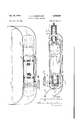
- Figure 1 is a broken sectional view of an oven compartment containing heating elements embodying features of this invention
- Fig. 2 is a sectional view of the structure illvjistrated in Fig. 1, taken on theline 2-2 there- 0';
- Fig. 3 is an enlarged sectional view of the structure illustrated in Fig. 1, taken on the line '3-3 thereof;
- Fig. 4 is an enlarged sectional view of the structure illustrated in Fig. 1, taken on thelihe 4'4 thereof;
- Fig. 5 is an enlarged sectional view of the structure illustrated in Fig. 1, taken on the line 5-5 thereof;
- Fig. 6 is an end view of the structure illustrfated in Fig. 5, as viewed from lines 6-6 there- 0
- Fig. '7 is a broken plan view of an oven compartment disclosing a heating element therefor which embodies a further form of this invention
- Fig. 8 is a diagrammatic view of the electric heating coiland terminals employed in the heating element illustrated in Fig. 7;
- Fig. 9 is an enlarged broken sectional View of the structure illustrated in Fig. '7, taken on the line 99 thereof, and
- Fig. 10 is an enlarged sectional view of the structure illustrated in Fig. 7, taken on the line Hl-l0 thereof.
- a 'form 01 the invention is illustrated, that wherein heating elements It! are supported on opposite 'side walls of a bottom well ll of an oven compartment l2.
- Each of the heating elements is constructed from a plurality of U-shaped strips 13 which are secured to end caps l4 and I5 to form a unit construction.
- the side walls of the U- shaped elements are lanced at it to provide a web ll therebetween which is arcuately formed, as illustrated, for receiving annular insulating washers 18 through which a heating coil 1'9 is threaded.
- the ends 2i of the coil are secured to knife blade contact terminals 22 which are supported on the end wall of the end cap l5 and insulated therefrom by the insulatin washers 23, as illustrated in Fig. 5.
- a bail 24 is riveted or otherwise secured to the end cap 14 in which a key-like slot 25 is provided by which the cap is secured to the headed supporting rivet 2B which is carried by the wall of the oven compartment.
- the opposite end of the heating element is supported by the blade terminals 22 in the terminal block 2'! provided in the rear wall of the well H.
- a stop element 28 is embossed in the side wall for aligning the headed rivet 26 with its slot 25.
- the terminal block 21 is made of insulating material and contains a pair of contact elements 29 mounted on through studs 3! to which the supply conductors 32 are attached in a conventional manner.
- the blade terminals 22 engage the contact elements 29, when mounted on the side of the stove, to complete the circuit to the heating coil mounted in the heating element.
- the rear end of the terminal block 2'! projects through the rear wall 34 of the oven with a front shoulder portion 35 abutting the rear wall of the oven well.
- the block 21 is retained in position by a spring clip 36 of sinuous form which engages the curved bottom web of a slot 31 provided in opposite faces of the book.
- the heating elements are readily mounted upon opposite side walls of the oven well by the insertion of the blade terminals into the terminal block and then securing the forward end upon the head of the rivet 25.
- the space therebetween in the oven well is radiantly heated and the heat is directed upwardly through the center of the oven to the top where it will move to the side walls and drop down to the heating elements.
- the air will be repeatedly heated and will move upwardly to the top of the compartment and then move outwardly and downwardly along the sides to the central open portion of the heating element. All portions of the compartment are equally and quickly heated, and any spillage which may occur will be prevented from falling upon the heating coils,
- heating units are illustrated as being applied to the side walls of the bottom Well, that the same heating units may also be employed at the top of the oven alone or in combination with the bottom heating elements. It was found, however, that a better convection flow of heat was obtained when the elements were utilized at the bottom of the compartment, as illustrated.
- a further form of the invention is illustrated, that wherein a continuous frame 4
- the frame is U-shaped in section, as illustrated more specifically in Fig.
- a plurality of insulating blocks 43 have a U'shaped outer contour to mate with the inner U-shaped surface of the frame with notches 44 at the top and bottom edges.
- the notches receive the projecting flange 42 of the frame and stabilize the insulating blocks and prevent them from tilting after being mounted in the frame.
- the frame edges are sprung apart when the blocks are tilted into vertical position.
- the insulating block is provided with an upper and lower slot 45 which communicates with apertures 46 in which the heating coil 41 is supported.
- An insulating block 48 is mounted in the rear portion of the frame for supporting the terminal blades 49 to which the ends 5! of the heating coil are attached.
- the heating coil 41 extends forwardly along one side of the frame across half of the front portion Where it is reversed and returned to the rear portion of the frame and to the opposite side thereof to the forward frame portion and reversely moved and returned along the side portion to the opposite blade terminal 49.
- the coil is in Series with the two blade terminals which are releasably connected to the terminals 53 of a terminal block 54 which is secured to the oven wall 55.
- a third terminal 56 is employed in both constructions for grounding the frame and guiding it into position in the conventional manner.
- a bail 51 is secured to the under side of the frame to extend across the bottom thereof at 58 for supporting the frame from the bottom 59 of the oven.
- the side walls 61 of the frame are provided with a plurality of louvres 62 by which air between the frame and the oven walls may pass directly over the heating coils to thereby aid in the convection flow of the heat upwardly in the central portion of the oven and downwardly along the side walls thereof.
- the frame rests in the lower portion of the oven below the door sill 64 and that the opening 65 in the terminal block 54 is larger than the terminal blades All to permit the entire frame to be tilted upwardly a suflicient amount to be withdrawn over the sill it without straining either the blade terminals 49 or the terminal block 54.
- the central portion of the oven bottom is entirely free of the heating elements and a proper distribution of radiant and convection heat is provided to uniformly heat all portions of the oven.
- the heat passes from the side wall over the heating coils of the heating elements and is directed upwardly in the central portion of the oven compartment. After the heat reaches the top of the oven it is forced to the side of the wall Where it moves downwardly to the bottom of the compartment, where it is again heated, and passed upwardly in the central portion thereof.
- the heating elements as pointed out hereinabove, are illustrated as bein mounted in the bottom of the oven compartment, it is within the purview of the invention to mount the units at the top of the compartment or both at the top and bottom of the compartment, following the conventional practice.
- a heating element for directing heat toward the center of an oven, a plurality of spaced troughlike channel elements, end caps to which said elements are secured in spaced relation, insulating washers supported in said elements, and a coil of resistance wire supported by said washers.
- a heating element for directing heat toward the center of an oven, a pair of end caps, channel elements spaced apart and having their webs secured to said caps, insulating washers in said elements, and a heating coil supported by said washers in said channels with end loops disposed in said end caps.
- a heating element for directing heat toward the center of an oven, a pair of end caps, channel elements spaced apart and having their webs secured to said caps, insulating washers in said elements, a heating coil supported by said Washers in said channel with end loops disposed in said end caps, and a terminal block on one of said end caps to which the ends of said coil are secured.
- a heating element for directing heat toward the center of an oven, a pair of end caps, channel elements spaced apart and having their webs secured to said caps, insulating washers in said elements, a heating coil supported by said washers in said channels with end loops disposed in said end caps, and a terminal block on one of said end caps to which the ends of said coil are secured, the opposite cap containing supporting 20 means ALFRED H. HABERSTUMP.
Landscapes
- Engineering & Computer Science (AREA)
- Chemical & Material Sciences (AREA)
- Combustion & Propulsion (AREA)
- Mechanical Engineering (AREA)
- General Engineering & Computer Science (AREA)
- Electric Stoves And Ranges (AREA)
Description
Dec. 27, 1949 A. H. HABERSTUMP ELECTRIC HEATING ELEMENT 4 Shets-Sheet 1 Filed Oct. 19, 1944 IN V EN TOR flTTaF/Vf/s.
e 2 WM HWL @m Dec. 27, 1949 A. H. HABERSTUMP 7 2,492,424
ELECTRIC HEATING ELEMENT Filed Oct. 19, 1944 4 Sheets-Sheet 2 A. H. HABERSTUMP 2,492,424
Patented Dec. 27, 1949 ELECTRIC HEATING ELEMENT Alfred H. 'Ha'berst'ump, Detroit, Mich., assignor to The Murray Corporation 'of America, Detroit, Mich., a corporation of Delaware Application October 19, 1944, Serial No. 559,345
4 Claims. 1
This invention relates to electric heating elements, and particularly to an electric heating element of a type to be employed in an oven of a cooking stove or the like.
It has been the practice in the art to employ electric heating elements for ovens of stoves which extend across the bottom or top thereof, or both across the top and bottom of the oven chamber. While the practice of disposing the heating element in the bottom of the chamber has proved satisfactory, nevertheless it is objectionable because all of the food particles which fall from the cooking utensil "or which boil thereover, fall upon the heating element or on a defleeting plate provided thereabove. The use of the deflecting plate or plates prevented a free flow of heat over all portions of the oven and, as a result, some parts of the oven were heated to a higher temperature than others.
In the construction of the present invention, the heating element may be supported either at the top or at the bottom of the'oven compartment or at both the top and bottom thereof, but are so constructed as to be disposed at the sides of the compartment leaving the central portion free of the heating element to thereby eliminate the deflector plate entirely. This permits a free and desirable application and circulation of the heat produced by the respective heating elements. Frame elements may be employed which are supported directly to the sides of the oven, or a continuous frame element may be utilized which snugly engages the front, back, and side walls, leaving the central part of the oven compartment free of the heating frame. The heating coils are supported within the frame 01' frames, the outwardly directed top flange of which prevents any food particles or liquids from spilling upon the heating coils.
Accordingly, the main objects of the invention are: to mount the heating coils at the side of an oven compartment to produce radiant and convection heat which reaches all portions of the oven interior; to provide a frame having projecting flanges which encompasses the heating l coils supported therein for protecting the coil against damage by spillage; to support a pair of heating elements on the side walls of an oven position to be readily removed therefrom;
to provide continuous frame "which is closely disposed adjacent to the front, rear, and side walls of an oven well for supporting heating coils therein leaving the central portion of the oven entir ly open and free of the heating elements; and in general to provide a removable heating element or elements for an oven compartment which is simple in construction and which heats the compartment at all points by radiant and convection heat flow.
Other objects and features of novelty of this invention will be specifically pointed out or will become apparent when referring, fora better understanding of the invention, to the following description taken in conjunction with the accompanying drawings, wherein Figure 1 is a broken sectional view of an oven compartment containing heating elements embodying features of this invention;
Fig. 2 is a sectional view of the structure illvjistrated in Fig. 1, taken on theline 2-2 there- 0';
Fig. 3 is an enlarged sectional view of the structure illustrated in Fig. 1, taken on the line '3-3 thereof;
Fig. 4 is an enlarged sectional view of the structure illustrated in Fig. 1, taken on thelihe 4'4 thereof;
Fig. 5 is an enlarged sectional view of the structure illustrated in Fig. 1, taken on the line 5-5 thereof;
Fig. 6 is an end view of the structure illustrfated in Fig. 5, as viewed from lines 6-6 there- 0 Fig. '7 is a broken plan view of an oven compartment disclosing a heating element therefor which embodies a further form of this invention;
Fig. 8 is a diagrammatic view of the electric heating coiland terminals employed in the heating element illustrated in Fig. 7;
Fig. 9 is an enlarged broken sectional View of the structure illustrated in Fig. '7, taken on the line 99 thereof, and
Fig. 10 is an enlarged sectional view of the structure illustrated in Fig. 7, taken on the line Hl-l0 thereof.
Referring to Figs. 1 to 6 inclusive, a 'form 01 the invention is illustrated, that wherein heating elements It! are supported on opposite 'side walls of a bottom well ll of an oven compartment l2. Each of the heating elements is constructed from a plurality of U-shaped strips 13 which are secured to end caps l4 and I5 to form a unit construction. The side walls of the U- shaped elements are lanced at it to provide a web ll therebetween which is arcuately formed, as illustrated, for receiving annular insulating washers 18 through which a heating coil 1'9 is threaded. The ends 2i of the coil are secured to knife blade contact terminals 22 which are supported on the end wall of the end cap l5 and insulated therefrom by the insulatin washers 23, as illustrated in Fig. 5.
A bail 24 is riveted or otherwise secured to the end cap 14 in which a key-like slot 25 is provided by which the cap is secured to the headed supporting rivet 2B which is carried by the wall of the oven compartment. The opposite end of the heating element is supported by the blade terminals 22 in the terminal block 2'! provided in the rear wall of the well H. A stop element 28 is embossed in the side wall for aligning the headed rivet 26 with its slot 25. The terminal block 21 is made of insulating material and contains a pair of contact elements 29 mounted on through studs 3! to which the supply conductors 32 are attached in a conventional manner. The blade terminals 22 engage the contact elements 29, when mounted on the side of the stove, to complete the circuit to the heating coil mounted in the heating element. The rear end of the terminal block 2'! projects through the rear wall 34 of the oven with a front shoulder portion 35 abutting the rear wall of the oven well. The block 21 is retained in position by a spring clip 36 of sinuous form which engages the curved bottom web of a slot 31 provided in opposite faces of the book. The heating elements are readily mounted upon opposite side walls of the oven well by the insertion of the blade terminals into the terminal block and then securing the forward end upon the head of the rivet 25.
When current is supplied to the heating elements, the space therebetween in the oven well is radiantly heated and the heat is directed upwardly through the center of the oven to the top where it will move to the side walls and drop down to the heating elements. The air will be repeatedly heated and will move upwardly to the top of the compartment and then move outwardly and downwardly along the sides to the central open portion of the heating element. All portions of the compartment are equally and quickly heated, and any spillage which may occur will be prevented from falling upon the heating coils,
drip pan or reflecting plate now being utilized. It is to be understood that while the heating units are illustrated as being applied to the side walls of the bottom Well, that the same heating units may also be employed at the top of the oven alone or in combination with the bottom heating elements. It was found, however, that a better convection flow of heat was obtained when the elements were utilized at the bottom of the compartment, as illustrated.
Referring to Figs. 7 to 10 inclusive, a further form of the invention is illustrated, that wherein a continuous frame 4| is utilized which closely engages the front, rear, and both side walls of the oven compartment. The frame is U-shaped in section, as illustrated more specifically in Fig.
10, with the open face presenting inwardly and having the end flanges reversely bent to project outwardly at 42. A plurality of insulating blocks 43 have a U'shaped outer contour to mate with the inner U-shaped surface of the frame with notches 44 at the top and bottom edges. The notches receive the projecting flange 42 of the frame and stabilize the insulating blocks and prevent them from tilting after being mounted in the frame. The frame edges are sprung apart when the blocks are tilted into vertical position. The insulating block is provided with an upper and lower slot 45 which communicates with apertures 46 in which the heating coil 41 is supported.
An insulating block 48 is mounted in the rear portion of the frame for supporting the terminal blades 49 to which the ends 5! of the heating coil are attached. The heating coil 41 extends forwardly along one side of the frame across half of the front portion Where it is reversed and returned to the rear portion of the frame and to the opposite side thereof to the forward frame portion and reversely moved and returned along the side portion to the opposite blade terminal 49. The coil is in Series with the two blade terminals which are releasably connected to the terminals 53 of a terminal block 54 which is secured to the oven wall 55. A third terminal 56 is employed in both constructions for grounding the frame and guiding it into position in the conventional manner.
A bail 51 is secured to the under side of the frame to extend across the bottom thereof at 58 for supporting the frame from the bottom 59 of the oven. The side walls 61 of the frame are provided with a plurality of louvres 62 by which air between the frame and the oven walls may pass directly over the heating coils to thereby aid in the convection flow of the heat upwardly in the central portion of the oven and downwardly along the side walls thereof. It will be noted that the frame rests in the lower portion of the oven below the door sill 64 and that the opening 65 in the terminal block 54 is larger than the terminal blades All to permit the entire frame to be tilted upwardly a suflicient amount to be withdrawn over the sill it without straining either the blade terminals 49 or the terminal block 54.
When applying the heating element to the stove, it is only necessary to place the element upon the sill 64 and move it rearwardly as it is tilted downwardly to permit the terminal blades 49 to enter the terminal block 54, after which the front portion of the frame is lowered to have the offset portions 65 of the bail 5'! rest upon the bottom 59 of the oven.
In either of the constructions herein described and illustrated, the central portion of the oven bottom is entirely free of the heating elements and a proper distribution of radiant and convection heat is provided to uniformly heat all portions of the oven. The heat passes from the side wall over the heating coils of the heating elements and is directed upwardly in the central portion of the oven compartment. After the heat reaches the top of the oven it is forced to the side of the wall Where it moves downwardly to the bottom of the compartment, where it is again heated, and passed upwardly in the central portion thereof. While the heating elements, as pointed out hereinabove, are illustrated as bein mounted in the bottom of the oven compartment, it is within the purview of the invention to mount the units at the top of the compartment or both at the top and bottom of the compartment, following the conventional practice.
What is claimed is:
1. In a heating element for directing heat toward the center of an oven, a plurality of spaced troughlike channel elements, end caps to which said elements are secured in spaced relation, insulating washers supported in said elements, and a coil of resistance wire supported by said washers.
2. In a heating element for directing heat toward the center of an oven, a pair of end caps, channel elements spaced apart and having their webs secured to said caps, insulating washers in said elements, and a heating coil supported by said washers in said channels with end loops disposed in said end caps. 4
3. In a heating element for directing heat toward the center of an oven, a pair of end caps, channel elements spaced apart and having their webs secured to said caps, insulating washers in said elements, a heating coil supported by said Washers in said channel with end loops disposed in said end caps, and a terminal block on one of said end caps to which the ends of said coil are secured.
4. In a heating element for directing heat toward the center of an oven, a pair of end caps, channel elements spaced apart and having their webs secured to said caps, insulating washers in said elements, a heating coil supported by said washers in said channels with end loops disposed in said end caps, and a terminal block on one of said end caps to which the ends of said coil are secured, the opposite cap containing supporting 20 means ALFRED H. HABERSTUMP.
REFERENCES CITED The following references are of record in the file of this patent:
UNITED STATES PATENTS Number Name Date 1,001,637 Gray Aug. 29, 1911 1,099,595 Fischer June 9, 1914 1,147,396 Hawley et a1 July 20, 1915 1,244,817 Willson Oct. 30, 1917 1,269,052 Clark et a1 June 11, 1918 1,389,397 Tactikos Aug. 30, 1921 1,426,187 Harrison Aug. 15, 1922 1,479,819 Kluever Jan. 8, 1924 1,543,692 Biebel June 30, 1925 1,638,452 Panajiotaros et a1. Aug. 9, 1927 1,652,686 Schoenfeld Dec. 13, 1927 2,019,780 G-ough Nov. 5, 1935 2,025,515 Jones Dec. 24, 1935 FOREIGN PATENTS Number Country Date 2,120 Austria Sept. 10, 1900
Priority Applications (1)
| Application Number | Priority Date | Filing Date | Title |
|---|---|---|---|
| US559345A US2492424A (en) | 1944-10-19 | 1944-10-19 | Electric heating element |
Applications Claiming Priority (1)
| Application Number | Priority Date | Filing Date | Title |
|---|---|---|---|
| US559345A US2492424A (en) | 1944-10-19 | 1944-10-19 | Electric heating element |
Publications (1)
| Publication Number | Publication Date |
|---|---|
| US2492424A true US2492424A (en) | 1949-12-27 |
Family
ID=24233245
Family Applications (1)
| Application Number | Title | Priority Date | Filing Date |
|---|---|---|---|
| US559345A Expired - Lifetime US2492424A (en) | 1944-10-19 | 1944-10-19 | Electric heating element |
Country Status (1)
| Country | Link |
|---|---|
| US (1) | US2492424A (en) |
Citations (14)
| Publication number | Priority date | Publication date | Assignee | Title |
|---|---|---|---|---|
| AT2120B (en) * | 1899-03-16 | 1900-09-10 | Dowsing Radiant Heat Company L | |
| US1001637A (en) * | 1911-04-20 | 1911-08-29 | Harold Gray | Electrical oven. |
| US1099595A (en) * | 1913-10-06 | 1914-06-09 | Franz Fischer | Process of and apparatus for heating. |
| US1147396A (en) * | 1912-08-20 | 1915-07-20 | Herman F Getze | Heater. |
| US1244817A (en) * | 1917-02-15 | 1917-10-30 | Russell A Willson | Electric heater for hot-water tanks. |
| US1269052A (en) * | 1917-07-05 | 1918-06-11 | Toronto Power Company Ltd | Electric-heater element. |
| US1389397A (en) * | 1920-01-23 | 1921-08-30 | Louis A Tactikos | Heater |
| US1426187A (en) * | 1921-04-21 | 1922-08-15 | Wilfrid M Harrison | Method of and means for vaporizing fuel for internal-combustion engines |
| US1479819A (en) * | 1922-02-02 | 1924-01-08 | Anne J Kluever | Heater |
| US1543692A (en) * | 1923-02-08 | 1925-06-30 | Westinghouse Electric & Mfg Co | Oven |
| US1638452A (en) * | 1925-12-07 | 1927-08-09 | Tom Peters | Self-basting rotary roaster |
| US1652686A (en) * | 1925-04-13 | 1927-12-13 | Magnavox Co | Combination radiant and convection heater |
| US2019780A (en) * | 1934-10-24 | 1935-11-05 | Chicago Electric Mfg Co | Electric heating unit |
| US2025515A (en) * | 1933-09-05 | 1935-12-24 | Meredith-Jones Hubert | Electric oven |
-
1944
- 1944-10-19 US US559345A patent/US2492424A/en not_active Expired - Lifetime
Patent Citations (14)
| Publication number | Priority date | Publication date | Assignee | Title |
|---|---|---|---|---|
| AT2120B (en) * | 1899-03-16 | 1900-09-10 | Dowsing Radiant Heat Company L | |
| US1001637A (en) * | 1911-04-20 | 1911-08-29 | Harold Gray | Electrical oven. |
| US1147396A (en) * | 1912-08-20 | 1915-07-20 | Herman F Getze | Heater. |
| US1099595A (en) * | 1913-10-06 | 1914-06-09 | Franz Fischer | Process of and apparatus for heating. |
| US1244817A (en) * | 1917-02-15 | 1917-10-30 | Russell A Willson | Electric heater for hot-water tanks. |
| US1269052A (en) * | 1917-07-05 | 1918-06-11 | Toronto Power Company Ltd | Electric-heater element. |
| US1389397A (en) * | 1920-01-23 | 1921-08-30 | Louis A Tactikos | Heater |
| US1426187A (en) * | 1921-04-21 | 1922-08-15 | Wilfrid M Harrison | Method of and means for vaporizing fuel for internal-combustion engines |
| US1479819A (en) * | 1922-02-02 | 1924-01-08 | Anne J Kluever | Heater |
| US1543692A (en) * | 1923-02-08 | 1925-06-30 | Westinghouse Electric & Mfg Co | Oven |
| US1652686A (en) * | 1925-04-13 | 1927-12-13 | Magnavox Co | Combination radiant and convection heater |
| US1638452A (en) * | 1925-12-07 | 1927-08-09 | Tom Peters | Self-basting rotary roaster |
| US2025515A (en) * | 1933-09-05 | 1935-12-24 | Meredith-Jones Hubert | Electric oven |
| US2019780A (en) * | 1934-10-24 | 1935-11-05 | Chicago Electric Mfg Co | Electric heating unit |
Similar Documents
| Publication | Publication Date | Title |
|---|---|---|
| US2134474A (en) | Oven | |
| US2415768A (en) | Electric oven | |
| GB1261250A (en) | Improved cooking unit | |
| US3072775A (en) | Electric heater assembly and method | |
| US2662963A (en) | Electric air heater | |
| GB1414230A (en) | Electric grill type cooking device | |
| US2492424A (en) | Electric heating element | |
| US2063407A (en) | Electric heating device | |
| US3301170A (en) | Electric broiler | |
| US3688084A (en) | Electric broiler heating unit | |
| US1817118A (en) | Appliance for grilling, toasting, and the like | |
| US2314592A (en) | Domestic appliance | |
| US1565539A (en) | Electric space heater | |
| US1721099A (en) | Electric strip heater | |
| US2137149A (en) | Electric heating unit | |
| US1949450A (en) | Low voltage heating element | |
| US3578949A (en) | Combination bake and auxiliary broil heater for a cooking appliance | |
| US2025515A (en) | Electric oven | |
| US2938102A (en) | Electric cooking apparatus | |
| US2566553A (en) | Warming oven | |
| US1966410A (en) | Baking apparatus | |
| US2622181A (en) | Electrical heating element for cooking range ovens | |
| US1154416A (en) | Electrically-heated oven. | |
| US2540877A (en) | Cabinet heater | |
| US2561125A (en) | Cooking device |