US2490102A - Magnetic field angular gradientometer - Google Patents
Magnetic field angular gradientometer Download PDFInfo
- Publication number
- US2490102A US2490102A US668992A US66899246A US2490102A US 2490102 A US2490102 A US 2490102A US 668992 A US668992 A US 668992A US 66899246 A US66899246 A US 66899246A US 2490102 A US2490102 A US 2490102A
- Authority
- US
- United States
- Prior art keywords
- magnetometer
- magnetic field
- magnetometers
- scale
- gradientometer
- Prior art date
- Legal status (The legal status is an assumption and is not a legal conclusion. Google has not performed a legal analysis and makes no representation as to the accuracy of the status listed.)
- Expired - Lifetime
Links
- 238000004804 winding Methods 0.000 description 7
- 241000669069 Chrysomphalus aonidum Species 0.000 description 4
- 238000006073 displacement reaction Methods 0.000 description 4
- 238000010276 construction Methods 0.000 description 2
- 239000013598 vector Substances 0.000 description 2
- 238000010586 diagram Methods 0.000 description 1
- 230000006698 induction Effects 0.000 description 1
- 238000005259 measurement Methods 0.000 description 1
- 238000012986 modification Methods 0.000 description 1
- 230000004048 modification Effects 0.000 description 1
Images

Classifications
-
- G—PHYSICS
- G01—MEASURING; TESTING
- G01R—MEASURING ELECTRIC VARIABLES; MEASURING MAGNETIC VARIABLES
- G01R33/00—Arrangements or instruments for measuring magnetic variables
- G01R33/02—Measuring direction or magnitude of magnetic fields or magnetic flux
- G01R33/022—Measuring gradient
Definitions
- This invention relates in general to an electrical system and more specifically to a magnetic gradientometer for surveying the magnetic field of a carrier or the like.
- the usual magnetic field gradientometer measures the difference in magnitude of two parallel field components at separate locations.
- the word selected, as used herein, is intended to mean that the components lie in the plane of rotation of the magnetometers at the location at which the device is operated.
- One object of this invention is to provide a system whereby the angular difference between the direction of the magnetic field at one point and the direction of that field at another point may be measured by a single reading of an instrument.
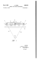
- Fig. 1 is a diagrammatic representation of the physical layout of a preferred form of the novel gradientometer including the mechanical connections and vectors representing magnetic field components, and
- Fig. 2 is a partial schematic diagram of the electrical connections of the system.
- magnetometers II and I2 Two self-aligning magnetometers II and I2, hereinafter referred to as magnetometers, are mounted, as shown in Fig. 1, at opposite ends of a rigid supporting member I3, the length of said member not being critical, but depending upon the application of the device.
- the magnetometers are so constructed as to orient themselves in the direction of the minimum magnetic field with the aid of a suitable control system.
- the control system is comprised of an amplifier 25, as in Fig. 2, and two motors I 4 and I6.
- Motor I4 aligns magnetometer I I and also drives a circular scale I5 which rotates about its axis.
- Motor I6 aligns magnetometer I2 and drives a pointer I'l, said pointer being mounted concentric to the axis of the scale I5.
- the scale and pointer show no relative motion so long as the two magnetometer units remain parallel to each other as would be the case in which the direction of the magnetic field components is the same at each end of the supporting member. When the field components at the respective ends of the supporting member are not in the same direction, the magnetometer units do not remain parallel and therefore produce a relative displacement between the scale and pointer.
- the amount of displacement may be read directly from scale I5 calibrated in terms of degrees, and this value is the angular difference between the directions of the magnetic field components at the points under survey.
- Vectors IDA and IUB in Fig. 1 represent the directions of the components of the. magnetic field and angle I8 is file actual angular gradient.
- Angle l8 as read from the scale is the indicated angular gradient which is equal to angle I9.
- Fig. 2 illustrates the path of signals throughout the system.
- the power source 23 provides alternating current of any practical voltage and frequency. For test purposes of this device and other applications involving magnetometers of the type employed herein, volts A. C. at 400 cycles per second has proved to be quite satisfactory.
- the A. C. voltage is fed directly to the driver transformers 21 and 28, amplifier 25 power supply and one of the fields of each motor, 24A of motor 24 and 26A of motor 26.
- the secondary windings of the driver transformers 21 and 28 are connected to the windings of magnetometer units 2
- a center tap on the secondary winding of each driver transformer is connected to the amplifier input channels.
- the amplifier outputs are connected respectively to the second motor field, 24B of motor 24 and 26B of motor 26.
- the orientator windings of the magnetometer serve to keep the magnetometer at right angles to the component of the ambient magnetic field which lies in the plane of rotation of the magnetometer.
- the output of the orientator windings is a series of balanced peaks, alternately positive and negative in character.
- the magnetometer becomes misoriented so that the orientator windings are no longer at right angles to the field the peaks become unbalanced, the direction of misalignment determining whether the positive or negative peaks decrease.
- the amplifier output increases and causes the motor to return the magnetometer to the oriented position.
- the direction of rotation of the motor depends on the polarity of the unbalanced peaks.
- the path of control data within the device is as follows: electrical impulses are set up within the magnetometer windings and applied to the amplifier input channels. From the amplifier, electrical impulses are transmitted to one field of one motor, depending upon which magnetometer is acting. The impulses are transformed into mechanical energy at the motor and serve to bring the magnetometer into orientation through a mechanical connection, in this case a wire belt, and also drives the pointer or scale through another belt, depending upon which motor is operating. These connections may be seen by study of Figs. 1 and 2.
- the motors employed are two-phase induction motors known as servomotors.
- the Kollsman type 766-04 was used in the model but any similar type is suitable.
- the type of indicator used herein is not limited to a rotating scale and pointer system but may be a sliding linear type of scale, an electrical indicator or other electro-mechanical types.
- a device for measuring, in one operation, the angular gradient between two selected magnetic field components comprising a rigid support having two magnetometers mounted at opposite ends thereon; an indicator having a rotatable circular scale mounted on its axis and a pointer mounted concentric to the axis of said scale; a control means associated with one of said magnetometers for aligning said magnetometer and said scale of said indicator in response to data therefrom, and means associated with the other of said magnetometers for aligning said other magnetometer and said pointer of said indicator in response to data therefrom.
- Magnetic indicator apparatus comprising pair of spaced moving-coil magnetometers having individual motive means for moving the respective coils of said magnetometers to positions corresponding to the direction of the magnetic field at the locations of the magnetometers, a first movable member connected to one of said motive means and adapted to be positioned thereby in accordance with the orientation of the one of said coils moved by said one motive means, and a second movable member connected to the other of said motive means and adapted to be positioned thereby in accordance with the orientation of the other of said coils, and means concentrically mounting said first and second movable members for simultaneous observation of the displacement thereof, whereby relative displacement of said members is readily ascertained.
- An apparatus of the character described comprising magnetometer means located at a pair of spaced points in a magnetic field and responsive to variations in the direction of the field at said points to orientate said magnetometer means in accordance with said variations, said magnetometer means including means for generating electric signals having characteristics variable in accordance with the variations in orientation of the respective magnetometer means, coaxially mounted indicating means for each of said magnetometer means, and motive means coupled to said indicating means and actuatable in response to said electric signals to orientate said indicating means in synchronism with the orientation of said magnetometer means.
- An apparatus of the character described comprising magnetometer means located at a pair of spaced points in a magnetic field and responsive to variations in the direction of the field at said points to orientate said magnetometer means in accordance with said variations, said magnetometer means including means for generating electric signals having characteristics variable in accordance with the variations in orientation of the respective magnetometer means, indicating means for each of said magnetometer means and including relatively rotatable members mounted on a common axis, and motive means coupled to said indicating means and actuatable in response to said electric signals to orientate said indicating means in synchro nism with the orientation of said magnetometer means.
- a device for measuring the angular gradient between two selected magnetic field components comprising a support having two magnetometers mounted at opposite ends thereon; an indicator having a rotatable circular scale mounted on its axis and a pointer mounted concentric to the axis of said scale; means associated with one of said magnetometers for aligning said magnetometer and said scale of said indicator in response to data therefrom, and means associated with the other of said magnetometers for aligning said other magnetometer and said pointer of said indicator in response to data therefrom.
Landscapes
- Physics & Mathematics (AREA)
- Condensed Matter Physics & Semiconductors (AREA)
- General Physics & Mathematics (AREA)
- Measuring Magnetic Variables (AREA)
Description
1949 J. H. STEIN 2,490,102
menu-1c FIELD ANGULAR emmmuwoumm Filad am 10, 1946 2 Sheets-Sheet 1 BY & 2
Dec. 6, 1949 J. H. STEIN FIELD ANGULAR GRADIENTOIETER 2 Sheets-Sheet 2 Filed lay L0, 1946 2 ym gm mmvrox.
Y W n E n r n S r I I H v m M J Y B Nu Rho RNiQR v Q nw Patented Dec. 6, 1949 UNITED STATES PATENT OFFICE MAGNETIC FIELD ANGULAR GRADIEN- TOME TER
(Granted under the act of March 3, 1883, as amended April 30,, 1928; 370 O. G. 757) 6 Claims.
This invention relates in general to an electrical system and more specifically to a magnetic gradientometer for surveying the magnetic field of a carrier or the like.
The usual magnetic field gradientometer measures the difference in magnitude of two parallel field components at separate locations. herein disclosed is a device to measure the angular difference between the directions of two selected field components without regard to their amplitude. The word selected, as used herein, is intended to mean that the components lie in the plane of rotation of the magnetometers at the location at which the device is operated.
Further advantages of this novel device are that the measurements may be made in one operation and the results may be read directly from a calibrated scale.
One object of this invention is to provide a system whereby the angular difference between the direction of the magnetic field at one point and the direction of that field at another point may be measured by a single reading of an instrument.
Further objects and advantages of this invention, as well as its construction, arrangement and operation, will be apparent from the following description and claims in connection with the accompanying drawings, in which,
Fig. 1 is a diagrammatic representation of the physical layout of a preferred form of the novel gradientometer including the mechanical connections and vectors representing magnetic field components, and
Fig. 2 is a partial schematic diagram of the electrical connections of the system.
Two self-aligning magnetometers II and I2, hereinafter referred to as magnetometers, are mounted, as shown in Fig. 1, at opposite ends of a rigid supporting member I3, the length of said member not being critical, but depending upon the application of the device. The magnetometers are so constructed as to orient themselves in the direction of the minimum magnetic field with the aid of a suitable control system.
The control system is comprised of an amplifier 25, as in Fig. 2, and two motors I 4 and I6. Motor I4 aligns magnetometer I I and also drives a circular scale I5 which rotates about its axis. Motor I6 aligns magnetometer I2 and drives a pointer I'l, said pointer being mounted concentric to the axis of the scale I5. The scale and pointer show no relative motion so long as the two magnetometer units remain parallel to each other as would be the case in which the direction of the magnetic field components is the same at each end of the supporting member. When the field components at the respective ends of the supporting member are not in the same direction, the magnetometer units do not remain parallel and therefore produce a relative displacement between the scale and pointer. The amount of displacement may be read directly from scale I5 calibrated in terms of degrees, and this value is the angular difference between the directions of the magnetic field components at the points under survey. Vectors IDA and IUB in Fig. 1 represent the directions of the components of the. magnetic field and angle I8 is file actual angular gradient. Angle l8 as read from the scale is the indicated angular gradient which is equal to angle I9.
Fig. 2 illustrates the path of signals throughout the system. The power source 23 provides alternating current of any practical voltage and frequency. For test purposes of this device and other applications involving magnetometers of the type employed herein, volts A. C. at 400 cycles per second has proved to be quite satisfactory. The A. C. voltage is fed directly to the driver transformers 21 and 28, amplifier 25 power supply and one of the fields of each motor, 24A of motor 24 and 26A of motor 26. The secondary windings of the driver transformers 21 and 28 are connected to the windings of magnetometer units 2| and 22 respectively. A center tap on the secondary winding of each driver transformer is connected to the amplifier input channels. The amplifier outputs are connected respectively to the second motor field, 24B of motor 24 and 26B of motor 26.
Briefly, the theory of operation is as follows: The orientator windings of the magnetometer serve to keep the magnetometer at right angles to the component of the ambient magnetic field which lies in the plane of rotation of the magnetometer. When the element is properly oriented, the output of the orientator windings is a series of balanced peaks, alternately positive and negative in character. When the magnetometer becomes misoriented so that the orientator windings are no longer at right angles to the field the peaks become unbalanced, the direction of misalignment determining whether the positive or negative peaks decrease. The amplifier output, in turn, increases and causes the motor to return the magnetometer to the oriented position. The direction of rotation of the motor depends on the polarity of the unbalanced peaks.
The path of control data within the device is as follows: electrical impulses are set up within the magnetometer windings and applied to the amplifier input channels. From the amplifier, electrical impulses are transmitted to one field of one motor, depending upon which magnetometer is acting. The impulses are transformed into mechanical energy at the motor and serve to bring the magnetometer into orientation through a mechanical connection, in this case a wire belt, and also drives the pointer or scale through another belt, depending upon which motor is operating. These connections may be seen by study of Figs. 1 and 2.
A full description of the construction and operation of the magnetometers is contained in copending application Serial Number 516,612 Unbalanced magnetometers of Otto H. Schmitt. A suitable amplifier for the system is completely described in copending application Serial Number 532,144, Orientation system, of Otto H. Schmitt. This amplifier is not the only type that can be used, but it has proved satisfactory in tests. A two-channel amplifier is required, however, to accommodate the two magnetometer inputs and two motor control circuits.
The motors employed are two-phase induction motors known as servomotors. The Kollsman type 766-04 was used in the model but any similar type is suitable.
The type of indicator used herein is not limited to a rotating scale and pointer system but may be a sliding linear type of scale, an electrical indicator or other electro-mechanical types.
It is to be understood that various modifications and changes may be made in this invention without departing from the spirit and scope thereof as set forth in the appended claims.
The invention described herein may be manufactured and used by or for the Government of the United States of America for governmental purposes without the payment of any royalties thereon or therefor.
What is claimed is:
1. A device for measuring, in one operation, the angular gradient between two selected magnetic field components, said device comprising a rigid support having two magnetometers mounted at opposite ends thereon; an indicator having a rotatable circular scale mounted on its axis and a pointer mounted concentric to the axis of said scale; a control means associated with one of said magnetometers for aligning said magnetometer and said scale of said indicator in response to data therefrom, and means associated with the other of said magnetometers for aligning said other magnetometer and said pointer of said indicator in response to data therefrom.
2. Magnetic indicator apparatus, comprising pair of spaced moving-coil magnetometers having individual motive means for moving the respective coils of said magnetometers to positions corresponding to the direction of the magnetic field at the locations of the magnetometers, a first movable member connected to one of said motive means and adapted to be positioned thereby in accordance with the orientation of the one of said coils moved by said one motive means, and a second movable member connected to the other of said motive means and adapted to be positioned thereby in accordance with the orientation of the other of said coils, and means concentrically mounting said first and second movable members for simultaneous observation of the displacement thereof, whereby relative displacement of said members is readily ascertained.
3. The apparatus defined in claim 2 wherein said first movable member is a circular scale, and said second movable member is a pointer.
4. An apparatus of the character described, comprising magnetometer means located at a pair of spaced points in a magnetic field and responsive to variations in the direction of the field at said points to orientate said magnetometer means in accordance with said variations, said magnetometer means including means for generating electric signals having characteristics variable in accordance with the variations in orientation of the respective magnetometer means, coaxially mounted indicating means for each of said magnetometer means, and motive means coupled to said indicating means and actuatable in response to said electric signals to orientate said indicating means in synchronism with the orientation of said magnetometer means.
5. An apparatus of the character described, comprising magnetometer means located at a pair of spaced points in a magnetic field and responsive to variations in the direction of the field at said points to orientate said magnetometer means in accordance with said variations, said magnetometer means including means for generating electric signals having characteristics variable in accordance with the variations in orientation of the respective magnetometer means, indicating means for each of said magnetometer means and including relatively rotatable members mounted on a common axis, and motive means coupled to said indicating means and actuatable in response to said electric signals to orientate said indicating means in synchro nism with the orientation of said magnetometer means.
6. A device for measuring the angular gradient between two selected magnetic field components, said device comprising a support having two magnetometers mounted at opposite ends thereon; an indicator having a rotatable circular scale mounted on its axis and a pointer mounted concentric to the axis of said scale; means associated with one of said magnetometers for aligning said magnetometer and said scale of said indicator in response to data therefrom, and means associated with the other of said magnetometers for aligning said other magnetometer and said pointer of said indicator in response to data therefrom.
JOHN H. STEIN.
REFERENCES CITED The following references are of record in the file of this patent:
UNITED STATES PATENTS Number Name Date 1,526,391 Stewart Feb. 17, 1925 1,721,375 De Koning July 16, 1929 1,971,189 Leibing Aug. 21, 1934 2,027 393 McCrea'ry Jan. 14, 1936 2,047,609 Antranikian July 14, 1936 2,308,566 Noxon a Jan. 19, 1943 2,407,202 Vacquier Sept. 3, 1946 FOREIGN PATENTS Number Country Date 25,645 Great Britain Oct. 6, 1910
Priority Applications (1)
| Application Number | Priority Date | Filing Date | Title |
|---|---|---|---|
| US668992A US2490102A (en) | 1946-05-10 | 1946-05-10 | Magnetic field angular gradientometer |
Applications Claiming Priority (1)
| Application Number | Priority Date | Filing Date | Title |
|---|---|---|---|
| US668992A US2490102A (en) | 1946-05-10 | 1946-05-10 | Magnetic field angular gradientometer |
Publications (1)
| Publication Number | Publication Date |
|---|---|
| US2490102A true US2490102A (en) | 1949-12-06 |
Family
ID=24684585
Family Applications (1)
| Application Number | Title | Priority Date | Filing Date |
|---|---|---|---|
| US668992A Expired - Lifetime US2490102A (en) | 1946-05-10 | 1946-05-10 | Magnetic field angular gradientometer |
Country Status (1)
| Country | Link |
|---|---|
| US (1) | US2490102A (en) |
Cited By (4)
| Publication number | Priority date | Publication date | Assignee | Title |
|---|---|---|---|---|
| US2644919A (en) * | 1950-11-25 | 1953-07-07 | Western Electric Co | Magnetic axis and polarity testing device |
| DE1623568B1 (en) * | 1967-04-05 | 1971-11-04 | Schonstedt Instrument Co | GRADIENT PROBE |
| US4077131A (en) * | 1976-07-20 | 1978-03-07 | The Marconi Company Limited | Magnetic compass arrangements |
| WO2006112750A1 (en) * | 2005-04-21 | 2006-10-26 | Yury Alexeevich Baurov | Method for recording a local spatio-temporal irregularity of the universe physical characteristics and a system for carrying out said method |
Citations (7)
| Publication number | Priority date | Publication date | Assignee | Title |
|---|---|---|---|---|
| US1526391A (en) * | 1920-07-30 | 1925-02-17 | Stewart Bros | Testing apparatus |
| US1721375A (en) * | 1925-11-03 | 1929-07-16 | Gen Electric | Meter-testing apparatus |
| US1971189A (en) * | 1933-02-01 | 1934-08-21 | Gen Electric | Magnetic detector |
| US2027393A (en) * | 1931-01-15 | 1936-01-14 | Rodney G Richardson | Cathode ray device |
| US2047609A (en) * | 1933-08-25 | 1936-07-14 | Antranikian Haig | Magnetic field direction and intensity finder |
| US2308566A (en) * | 1940-06-13 | 1943-01-19 | Bendix Aviat Corp | Magnetic repeater or compass |
| US2407202A (en) * | 1941-07-21 | 1946-09-03 | Gulf Research Development Co | Apparatus for responding to magnetic fields |
-
1946
- 1946-05-10 US US668992A patent/US2490102A/en not_active Expired - Lifetime
Patent Citations (7)
| Publication number | Priority date | Publication date | Assignee | Title |
|---|---|---|---|---|
| US1526391A (en) * | 1920-07-30 | 1925-02-17 | Stewart Bros | Testing apparatus |
| US1721375A (en) * | 1925-11-03 | 1929-07-16 | Gen Electric | Meter-testing apparatus |
| US2027393A (en) * | 1931-01-15 | 1936-01-14 | Rodney G Richardson | Cathode ray device |
| US1971189A (en) * | 1933-02-01 | 1934-08-21 | Gen Electric | Magnetic detector |
| US2047609A (en) * | 1933-08-25 | 1936-07-14 | Antranikian Haig | Magnetic field direction and intensity finder |
| US2308566A (en) * | 1940-06-13 | 1943-01-19 | Bendix Aviat Corp | Magnetic repeater or compass |
| US2407202A (en) * | 1941-07-21 | 1946-09-03 | Gulf Research Development Co | Apparatus for responding to magnetic fields |
Cited By (4)
| Publication number | Priority date | Publication date | Assignee | Title |
|---|---|---|---|---|
| US2644919A (en) * | 1950-11-25 | 1953-07-07 | Western Electric Co | Magnetic axis and polarity testing device |
| DE1623568B1 (en) * | 1967-04-05 | 1971-11-04 | Schonstedt Instrument Co | GRADIENT PROBE |
| US4077131A (en) * | 1976-07-20 | 1978-03-07 | The Marconi Company Limited | Magnetic compass arrangements |
| WO2006112750A1 (en) * | 2005-04-21 | 2006-10-26 | Yury Alexeevich Baurov | Method for recording a local spatio-temporal irregularity of the universe physical characteristics and a system for carrying out said method |
Similar Documents
| Publication | Publication Date | Title |
|---|---|---|
| US2468554A (en) | Apparatus for magnetic field investigation | |
| US2695165A (en) | Electromagnetic accelerometer | |
| US2555209A (en) | Method and apparatus for measuring the values of magnetic fields | |
| US3077760A (en) | Self-testing gyroscope | |
| US2373096A (en) | Magnetic pick-off for sensitive instruments | |
| US2396244A (en) | 360u deg. resistance type transmitter | |
| US2269453A (en) | Device for detecting displacements | |
| US2476273A (en) | Apparatus sensitive to magnetic fields | |
| US2464057A (en) | Earth inductor compass | |
| US2490102A (en) | Magnetic field angular gradientometer | |
| US2518513A (en) | Method and apparatus for measuring magnetic fields | |
| US3295379A (en) | Spherically symmetric gyro | |
| US2376883A (en) | Dynamic earth inductor compass | |
| US2878445A (en) | Three-axis torquer and displacement detector | |
| US3397358A (en) | Rotating coil magnetometer with means to compensate for variations in rotational speed | |
| US2277027A (en) | Telemetric system | |
| US2887873A (en) | Method of measuring and compensating for deviation errors in earth's field sensitivedirection indicators | |
| US2435276A (en) | Magnetic field indicating means | |
| US2786179A (en) | Flux detector | |
| US3564402A (en) | Apparatus for measuring the strength and direction of magnetic fields utilizing a piezoelectric crystal | |
| US2488341A (en) | Detection system | |
| US2403091A (en) | Compass control system | |
| US1047157A (en) | Device for determining direction. | |
| US2097226A (en) | Electric meter | |
| US2709783A (en) | Magnetic incremometer or gradiometer |