US2490081A - High-frequency apparatus - Google Patents
High-frequency apparatus Download PDFInfo
- Publication number
- US2490081A US2490081A US452102A US45210242A US2490081A US 2490081 A US2490081 A US 2490081A US 452102 A US452102 A US 452102A US 45210242 A US45210242 A US 45210242A US 2490081 A US2490081 A US 2490081A
- Authority
- US
- United States
- Prior art keywords
- coil
- potential
- tank
- circuit
- connection
- Prior art date
- Legal status (The legal status is an assumption and is not a legal conclusion. Google has not performed a legal analysis and makes no representation as to the accuracy of the status listed.)
- Expired - Lifetime
Links
Images
Classifications
-
- A—HUMAN NECESSITIES
- A61—MEDICAL OR VETERINARY SCIENCE; HYGIENE
- A61N—ELECTROTHERAPY; MAGNETOTHERAPY; RADIATION THERAPY; ULTRASOUND THERAPY
- A61N1/00—Electrotherapy; Circuits therefor
- A61N1/40—Applying electric fields by inductive or capacitive coupling ; Applying radio-frequency signals
Definitions
- an electron tube oscillator having a tankv circuit including an inductance, a portion of said inductance consisting of a tubular coil, a tubular induction heating coil, tubular leads connecting said'he'at' j ing coil and said first mentioned c'oil, a fluid co nection on said first mentioned coil, means plac ing said fluid connectionat ground potentialia fluid connection on said' heatingcoil at a point of equal potential with. said first mentionedcon nection, and a source of plate voltage for' said" oscillator, one terminal of said source being connected to said inductance.
Description
Dec. 6, 1949 EJMITTELMANN 2,490,081
HIGH-FREQUENCY APPARATUS Filed July 23, 1942 fizz/972%)" Eazyezze flfzxeZmalm WZW rials}.
Patented Dec. 6, 1949 UNITED STATES PATENT OFFICE 2,490,081 HIGH-FREQUENCY APPARATUS Eugene Mittelmann, Chicago, 111. Application July 23, 1942, Serial No. 452,102
4 Claims.
My invention relates to oscillators of the type used for medical, industrial and similar purposes, and is particularly directed to means for making the exposed parts of the apparatus safe for the operator to handle, so far as the possibility of contact with high D. C. or low frequency power supply potentials is concerned.
In the usual kind ofhigh frequency heat treatment generator, electron tubes are used in an oscillator circuit for generating the desired high frequency power. Typical medical applications transfer this power to the patient by electrodes which are, in effect, simple elements of a condenser, with the patient constituting a part of the dielectric. Common industrial applications transfer the power by an induction coil, the object to be heat treated being placed in the field of the coil.
Persons working with the apparatus are exposed to contact with the electrodes or with the coils, as the case may be. Hence, these parts must be carefully insulated from the plate voltage as supplied to the electron tubes, since it generally is a dangerously high potential with respect to ground; It is usual to secure such insulation either. by the application of intermediate coupling condensers, or by the use of secondary coils inductively coupled to the primary or tank coil, which is at plate potential. In the case of the couplingcondenser, the safety limit is the breakdown voltage of the condenser dielectric; in the case of the inductively coupled coils, the limit is the spacing between coils, which determines the flashover potential. Neither of these limits, under practical conditions, gives satisfactory assurance of safety.
It is an object of this invention to provide a circuit for high frequency generators in which the output connections or electrodes are at ground potential.
, A further object of my invention is to facilitate water cooling of the heating coil by providing a circuit in which. the inlet and outlet connections for the cooling, water can be at ground potential.
Various modes in which my invention may be utilized are illustrated in the accompanying drawings, in whichjl.
. Fig. 1 is a wiring diagram of a high frequency generator witli' which heating electrodes of the condenser type are used;
, Fig. 2 is a diagram of a similar type of generator, using an induction coil for transferring energy to the material treated;
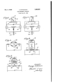
Fig. 3 is a diagram of a portion of a circuit corresponding generally 'to Fig. 2, showing how I may 2 provide for water cooling of the heating coil and part of the tank coil;
Fig. 4 is a diagram of a circuit equivalent to that of Fig. 3, illustrating how the arrangement of Fig. 3 constitutes a bridge'circuit; and
Fig. 5 is a modification of the circuit shown in Fig. 3.
Figs. 1 and 2 show a push-pull oscillator circuit, including electron tubes ID, a source of plate voltage 12, and a tank circuit in which the principal elements are the tank inductance or coil indicated generally as l4, and the tank condenser l6. In Fig. 1, radio frequency energy generated by the oscillator is transferred to the subject material by electrodes l8, coupled to the tank coil by condensers 20. In Fig. 2, the energy is transferred by the heating coil 22, which may be directly connected to the tank coil M, as shown, when my invention is employed.
One aspect of my invention consists in providing a balanced push-pull generator, symmetrically arranged so that the point at which the plate supply lead enters the tank circuit is at zero high frequency potential, or, let us say, at the average high frequency potential. I then ground this point, which is the positive plate supply terminal. The customary practice, of course, has been to ground the cathode or negative terminal. The ground connection in my circuit is indicated at 24 in the drawings.
In a circuit which is both mechanically and electrically symmetrical, this ground connection will be at the center of the tank coil i l. Grounding the tank coil in single-ended circuits would be impractical because of the very large capacity of the plate power supply equipment to ground; in the balanced push-pull oscillator, however, since the capacity of the power supply unit is always between points of zero or mid-potential as described above, the electrical conditions in the circuit would be unchanged, so far as the high frequency is concerned. The advantages of such a system in both industrial and electro-medical applications will be readily understood. Insulation for high voltages is necessary only in the components associated with the negative terminal of the power supply. Ordinarily there are parts which do not oiier any hazard to the operator in case of insulation failure. For instance, the transformers and other parts in the filament circuits of the oscillator tubes do not have to be accessible under normal working conditions.
With the positive high voltage terminal grounded, it is still advisable, in the usual case, to use coupling condensers 20, in order to maintain so far as possible a balanced distribution of the high frequency potential. But even if the dielectric in one of these condensers should fail, thus short-circuiting the condenser and connecting one of the electrodes l8 directly to the tank coil, nothing more serious than a change in the high frequency potential distribution would result. Usually this would not be severe enough to change very much the potential of the object with which the electrode l8 might be in contact.
In heat treatment generators using an inductor coil 22, advantage may be taken of the efliciency of an autotransformer, since the output leads may be conductively coupled to taps on the tank coil as shown in Fig. 2.
In numerous heat treatment applications, the temperatures reached are so high that it becomes necessary to cool the coil 22. doing this is to form the coil of a tubular conductor, and-to circulatewater through the coil. With circuits commonly used, however, insulation of the water supply is a serious problem and gives rise to many difliculties, both in design and maintenance. overcome by my invention, which makes it possible to have the inlets and outlets for the cooling water at ground potential.
Fig. 3 illustrates one practical arrangement which may be employed. As before, [4 and I6 represent the tank inductance and tank condenser, respectively, of a high frequency generator, the other parts of which are not illustrated, but may be as shown in Figs. 1 and 2, or any equivalent arrangement. Portions L1, L2 and L3 make up the total inductance of the tank coil l4, L3 being the mid-portion, having the number of turns desired between the taps for heating coil leads. L3 is a hollow tube coil with a water inlet 26 at its midpoint. The water inlet is grounded, i. e., it is connected to the positive terminal of the plate supply. The hollow tube is continued to form the leads 28 and 39, which serve both for electrical and water conducting connection to the induction heating coil 22. The latter also has a water connection at its midpoint, designated as 32. By any suitable means, not illustrated, water, or other cooling fluid may be cir-, culated through the tubular coils, to keep the coil 22 at a safe temperature.
The circualting water and the connections to the water supply apparatus will not affect the electrical characteristics of the circuit, because both inlet and outlet areat ground potential.
This fact is illustrated in Fig. 4, which is a diagram of the equivalent circuit of Fig. 3, laid out in the well known representation of a four-arm bridge. The branches of L3 will be equal and the branches of L4 will be equal, when these coils are center-tapped, as previously described. With One Way of These difilculties are vary the coupling as may be desirable for maximum power transfer to the object being heated. An arrangement which is more flexible in this respect as shown in Fig. 5. The heating coil 22 is made of tubing, with a connection 32. The leads 28 and 30, however, run to another tubing coil 34, which carries the other connection, here designated as 36. The leads 28 and 30 are extended as 28a and 30a to taps on the coil I 4, and these taps may be adjusted as desired for optimum impedance matching. The inductance value of the coil 34 is preferably made as large as practical with respect to that of the heating coil 22,
these branches equalin impedance, points 26 and 32 will be at the same high frequency potential, and hence if one is .groundedthe other will be at ground potential. I j I It is possible to balance the bridge arrangement, and thus to have 26 and 32 at equal potential; even when the two arms of inductances L3, and Li are not equal, but when the impedance ratio of the two parts of the L3 side of the bridge is the same as the ratio of the two parts of the L4 side. with regard to the cooling system.
With the cooling fluid circulating through'a part. of the tankcoil. as Fig. 3. it is not convenient to chang the taps on, the tank coil to Thus there is no insulation problem at all in order to minimize its shunting efiect. If a point on the tank coil is grounded as at 24, points of equal potential may be found on the coils 22 and 34. Locating the connections 32 and 36 at these points permits circulation of cooling fluid by any desired type of apparatus without any efiect on the electrical conditions in the circuit.
In each case described, the and electrodes (or coil) will be at ground P0: tential, so far as the plate supply voltage is-concerned. These are the only parts with which the operator or user would be likely to come in contact in the ordinary use-of the apparatus. Thus I have provided an arrangement which for practical purposes elimintes the hazard of electrocution always present with conventional apparatus.
Furthermore, I have substantiallyreduced the diiiculties involved in connection with cooling an induction heating coil by entirely eliminatingv the necessity for insulation of the apparatu s'used to supply water or other cooling fluid.
As will be understood by those familiar with the electronic art, some changes may be made in the arrangements here described, by the modifipower transfer leads cation of various parts, or the use of mechanical or electrical equivalents without departing from the real spirit and purpose of my invention. "The specific examples given are intended as illustraj-I tive only, and not as limitative of the scope oi my invention. It is my intention to cover by my claims any modifications .of structural or .elec trical arrangement, or use of mechanical or elec trical equivalents, which may be reasonably in} cluded within their scope.
In the claimsI use the generalterm power transfer means to include condenser type electrodes, as illustrated in Fig.. 1,, or inductor heating cells as shown in Fig. 2, for example. I
I claim:
1. In apparatus of the kind described, an electron tube oscillator having a tankv circuit including an inductance, a portion of said inductance consisting of a tubular coil, a tubular induction heating coil, tubular leads connecting said'he'at' j ing coil and said first mentioned c'oil, a fluid co nection on said first mentioned coil, means plac ing said fluid connectionat ground potentialia fluid connection on said' heatingcoil at a point of equal potential with. said first mentionedcon nection, and a source of plate voltage for' said" oscillator, one terminal of said source being connected to said inductance.
2. In high frequency heatin apparatus; a bal anced push-pull electron tube oscillator having a tank circuit including a tubularjcoil, a tubular heater inductor, tubular leads connectingsaid coil and said inductor, a fluid connection at the electrical center of. said 0011,, said connection being at ground potential, a fluid connection on said inductor, also at groundpotentialjand a nected in parallel with said inductor coil, and
commmunicating therewith for fluid flow, leads extending from said inductor coil to taps on said second coil, a fluid inlet connection on one of said tubular coils, and a fluid outlet connection on the other of said tubular coils at a point having the same high frequency potential as said inlet connection.
4. High frequency heating apparatus including a balanced push-pull electron tube oscillator having a tank circuit including an inductance, a. tubular heater inductor, a second tubular coil communicating for fluid flow with said inductor, a fluid connection at the electrical center of said inductor, said connection being at ground potential, a fluid connection on said second tubular coil, also at ground potential, a tap on said inductance at ground potential, leads from said inductor to taps on said inductance, and a source Radio, for January 1941, page 85.
6 of plate voltage for said oscillator, the positive terminal of said source being connected to one of said points of ground potential.
EUGENE MII'I'ELMANN.
REFERENCES CITED The following references are of record in the file of this patent:
UNITED STATES PATENTS Number Name Date Re. 19,371 Gebhard Nov. 13, 1934 1,986,353 Northrup Jan. 1, 1935 2,223,835 Smith Dec. 3, 1940 2,229,680 Somes Jan. 28, 1941 2,288,362 McArthur June 30, 1942 2,342,789 Cassen Feb. 29, 1944 FOREIGN PATENTS Number Country Date 789,495 France Aug. 19, 1935 OTHER REFERENCES
Priority Applications (1)
| Application Number | Priority Date | Filing Date | Title |
|---|---|---|---|
| US452102A US2490081A (en) | 1942-07-23 | 1942-07-23 | High-frequency apparatus |
Applications Claiming Priority (1)
| Application Number | Priority Date | Filing Date | Title |
|---|---|---|---|
| US452102A US2490081A (en) | 1942-07-23 | 1942-07-23 | High-frequency apparatus |
Publications (1)
| Publication Number | Publication Date |
|---|---|
| US2490081A true US2490081A (en) | 1949-12-06 |
Family
ID=23795044
Family Applications (1)
| Application Number | Title | Priority Date | Filing Date |
|---|---|---|---|
| US452102A Expired - Lifetime US2490081A (en) | 1942-07-23 | 1942-07-23 | High-frequency apparatus |
Country Status (1)
| Country | Link |
|---|---|
| US (1) | US2490081A (en) |
Cited By (3)
| Publication number | Priority date | Publication date | Assignee | Title |
|---|---|---|---|---|
| US2698386A (en) * | 1950-11-21 | 1954-12-28 | Rca Corp | Push-pull sine wave oscillator |
| US3316499A (en) * | 1963-10-14 | 1967-04-25 | Zinn Stanley | Water cooled power oscillator |
| FR2468274A1 (en) * | 1979-10-23 | 1981-04-30 | Tetra Pak Int | DEVICE FOR WELDING A THERMOPLASTIC COATING PACKAGING MATERIAL COMPRISING A LAYER OF ELECTRO-CONDUCTIVE MATERIAL, BY A HIGH FREQUENCY MAGNETIC FIELD |
Citations (7)
| Publication number | Priority date | Publication date | Assignee | Title |
|---|---|---|---|---|
| USRE19371E (en) * | 1928-12-22 | 1934-11-13 | Inductance system | |
| US1986353A (en) * | 1931-09-21 | 1935-01-01 | Ajax Electrothermic Corp | Induction furnace method and apparatus |
| FR789495A (en) * | 1934-08-01 | 1935-10-29 | Improvements to suspended type electric welding machines | |
| US2223835A (en) * | 1938-01-29 | 1940-12-03 | Rca Corp | Ultra high frequency device |
| US2229680A (en) * | 1938-05-26 | 1941-01-28 | Howard E Somes | Polyphase high frequency heating device |
| US2288362A (en) * | 1940-08-17 | 1942-06-30 | Gen Electric | Electric valve frequency changer |
| US2342789A (en) * | 1941-04-19 | 1944-02-29 | Westinghouse Electric & Mfg Co | Supervoltage X-ray tube |
-
1942
- 1942-07-23 US US452102A patent/US2490081A/en not_active Expired - Lifetime
Patent Citations (7)
| Publication number | Priority date | Publication date | Assignee | Title |
|---|---|---|---|---|
| USRE19371E (en) * | 1928-12-22 | 1934-11-13 | Inductance system | |
| US1986353A (en) * | 1931-09-21 | 1935-01-01 | Ajax Electrothermic Corp | Induction furnace method and apparatus |
| FR789495A (en) * | 1934-08-01 | 1935-10-29 | Improvements to suspended type electric welding machines | |
| US2223835A (en) * | 1938-01-29 | 1940-12-03 | Rca Corp | Ultra high frequency device |
| US2229680A (en) * | 1938-05-26 | 1941-01-28 | Howard E Somes | Polyphase high frequency heating device |
| US2288362A (en) * | 1940-08-17 | 1942-06-30 | Gen Electric | Electric valve frequency changer |
| US2342789A (en) * | 1941-04-19 | 1944-02-29 | Westinghouse Electric & Mfg Co | Supervoltage X-ray tube |
Cited By (4)
| Publication number | Priority date | Publication date | Assignee | Title |
|---|---|---|---|---|
| US2698386A (en) * | 1950-11-21 | 1954-12-28 | Rca Corp | Push-pull sine wave oscillator |
| US3316499A (en) * | 1963-10-14 | 1967-04-25 | Zinn Stanley | Water cooled power oscillator |
| FR2468274A1 (en) * | 1979-10-23 | 1981-04-30 | Tetra Pak Int | DEVICE FOR WELDING A THERMOPLASTIC COATING PACKAGING MATERIAL COMPRISING A LAYER OF ELECTRO-CONDUCTIVE MATERIAL, BY A HIGH FREQUENCY MAGNETIC FIELD |
| US4371768A (en) * | 1979-10-23 | 1983-02-01 | Tetra Pak International Ab | Arrangement for the sealing of thermoplastic-coated packing material |
Similar Documents
| Publication | Publication Date | Title |
|---|---|---|
| US2213820A (en) | High frequency apparatus for therapeutic and surgical uses | |
| US2130758A (en) | Electrode for diathermy treatment and the like | |
| US2656839A (en) | Electrotherapeutic oscillator | |
| US2490081A (en) | High-frequency apparatus | |
| US2430640A (en) | Induction heating system with alternately energized coaxial conductors | |
| Sloan | A radiofrequency high-voltage generator | |
| US8242639B2 (en) | Inductive rotary joint with low loss supply lines | |
| US1753408A (en) | Inductance system | |
| US2462903A (en) | Oscillator generator | |
| US2252941A (en) | Oscillating circuits for electrotherapeutics | |
| US2045034A (en) | Device for heating incandescible cathodes | |
| US3810025A (en) | Field emission type electron gun | |
| US1857029A (en) | Cooled radiofrequency apparatus | |
| US2438595A (en) | High-frequency generator | |
| US2171670A (en) | Electrotherapeutic device | |
| US2076368A (en) | High frequency power supply system | |
| US2160098A (en) | Fluid cooled elements for radio circuit | |
| US2081425A (en) | High frequency transmission system | |
| US2105568A (en) | Apparatus for diathermic treatment | |
| US2105749A (en) | Diathermy apparatus | |
| US2224649A (en) | Ultra high frequency circuits | |
| KR101918357B1 (en) | Inductively Coupled Plasma System By Using Radio-Frequency Power | |
| US2542841A (en) | High-frequency coupling apparatus | |
| US1963131A (en) | Fluid cooling for electron emission tubes | |
| US3316499A (en) | Water cooled power oscillator |