US2490056A - Measuring device using a rotating trap chamber having a varying peripheral speed - Google Patents
Measuring device using a rotating trap chamber having a varying peripheral speed Download PDFInfo
- Publication number
- US2490056A US2490056A US499802A US49980243A US2490056A US 2490056 A US2490056 A US 2490056A US 499802 A US499802 A US 499802A US 49980243 A US49980243 A US 49980243A US 2490056 A US2490056 A US 2490056A
- Authority
- US
- United States
- Prior art keywords
- receptacle
- receptacles
- chamber
- fluent material
- speed
- Prior art date
- Legal status (The legal status is an assumption and is not a legal conclusion. Google has not performed a legal analysis and makes no representation as to the accuracy of the status listed.)
- Expired - Lifetime
Links
Images
Classifications
-
- B—PERFORMING OPERATIONS; TRANSPORTING
- B65—CONVEYING; PACKING; STORING; HANDLING THIN OR FILAMENTARY MATERIAL
- B65B—MACHINES, APPARATUS OR DEVICES FOR, OR METHODS OF, PACKAGING ARTICLES OR MATERIALS; UNPACKING
- B65B1/00—Packaging fluent solid material, e.g. powders, granular or loose fibrous material, loose masses of small articles, in individual containers or receptacles, e.g. bags, sacks, boxes, cartons, cans, or jars
- B65B1/30—Devices or methods for controlling or determining the quantity or quality or the material fed or filled
- B65B1/36—Devices or methods for controlling or determining the quantity or quality or the material fed or filled by volumetric devices or methods
Definitions
- the present invention relates to measurin filler apparatus for fluent material in manufacturing packages and the like, and more particularly is directed to mechanisms for delivering or feeding to automatic infusion package making and filling machines, tea, coffee, etc. in predeterminated quantities or charges from a suitable bulk source.
- infusion packages such as teaballs and the like
- measured quantitles of tea or other filling material must be intermittently fed to the package bags being manufactured from a bulk supply source while preserving at all times the fluent condition of the filling material.
- the present invention provides an improved mechanism to successfully give results of the character described adapted'for use in connection with super high-speed packaging machines.
- a mechanism of the character described which shall comprise relatively few and simple parts that are easily assembled and incorporated in the construction of automatic machines for making complete fusion packages, or the like, which shall maintain a supply of predetermined quantities of filler or charges with certainty and reliability, which shall operate smoothly and be substantially free from vibration, which shall be inexpensive to construct yet capable of large output capacity in super high-speed machines, and which shall be practical and. efficient to a high degree in use.
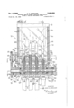
- Fig. 1 is a front elevational view of a supply feed measuring mechanism constructed to embody the invention adapted to be applied as a filler to a super high-speed package manufacturing machine, partly broken away to expose the interior constructions.
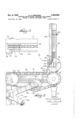
- Fig. 2 is a side elevational view of the improved mechanism shown in Fig. 1
- Fig. 3 is a fragmentary top view of the eccentrically mounted sprocket drive portion shown in Fig. 2.
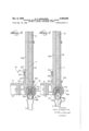
- Fig. 7 is a cross-sectional view similar to Fig. 6 showing the position of the parts when the measuring receptacle is in full discharging position;
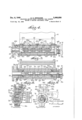
- Figs. 8 and 9 are fragmentary cross-sectional 2 views taken on lines in Fig. 1 showing the assembly and quantity adjustment details, respectively.
- 26 denotes an improved feed or charge measuring mechan-v ism constructed to embody the invention which may be incorporated in a super high-speed fully automatic machine for making complete filled packages, such as tea-balls and like articles in large scale production, in the manner more fully described in applicants inventions Ser. Nos. 456,- 289, now Patent No. 2,475,617, issued July 12, 1949, and 486,196, which has become abandoned, filed July 9, 1942 and May 3, 1943, respectively for Infusion package manufacture and filler apparatus for measuring a feed supply in packaging fluent products, respectively, copending.
- the packaging machine is here indicated by a fragmentary supporting frame portion M which locates the improved mechanism 2! in a proper position for receiving a controlled bulk supply of a fluent product, such as tea, T, to be packaged, and delivered in successive measured charges to bags in the manufacture of tea-balls or the like through suitable stationary funnels or spouts 2
- the complete mechanism 20 may include a control supply chamber 23 of adequate capacity from which the fluent material, T, being packed in the form of tea-balls is automatically drawn as required for continuous operation of the packaging machine, as for example as shown and described in said copending applications.
- the bottom or lower end of said chamber 23 may communicate with upper inlet ends 24a of a plurality of branch channels 24 through downwardly tapered intake chutes 25.
- each channel 24 As here shown four channels 24 construction is used, it being understood that any number of channels 24 from one to as many as required may be utilized in practicing the' invention.
- the opposite side walls 241) of each channel 24 below the chutes 25 may be made so as to permit being flexed for vibration by a suitable shimmying or shaker means connected to mid-portions thereof for agitating the fluent material T passing therethrough to retain the flow condition thereof and to insure against clogging, the upper ends of said side walls being fixedly secured to said intake chutes 25.
- Lower outlet ends 240 of each channel 24 passes the fluent material T to measuring devices 26 each of which discharges uniformly 8-8 and 9--9, respectively,
- Said member 256 is mounted to rtate continuously in spaced bearing blocks 2 each having a packing gland 25d as shown. in Figs. 1 and 5, and is turned through a suitable variable speed drive, such as driven sprocket 2! secured to said member 2512 and chain 28 connecting with an intermediate" sprocket Ell-having an eccentric hub 29a mounted'to turn witlra main shaft 353 driven in timed relation from a power transmission operating the packagingmachine in any well understood manner.
- the packing gland 2601 forms a seal to keep oil and otherforeign matter from reaching into receptacles 26a.
- variable speed drive through chain ZQ-requires a-continuousslack take-up as for example, idlersprocket which ismounted to turn on arm 3 id of a rock lever 3 I,
- lever being pivoted at 34 to the machine 3.
- the spaced receptacles 25a in cylinder member 26b of device 2e are each formed to provide a slideway side walls 256, and preferably has at least one segment 26; forming one of said walls of each slideway 28c made of an extremely hard steel, or the like material, so the peripherial edge 25g thereof mayserve as a cutter in the manner hereinafter described.
- the other segment portions of cylinder member 261) may be made of another metal brazed or bolted, as at 2672, to cutter segment 28f as indicated in Figs. 6 and 8.
- each bottom piece 26 is provided with an open slot 25k through whichexte'nds a crank portion 32a of an inner shaft 32 fitted within an axial bore 28m provided in cylinder member 251), the shaft 32 has spaced bearing portions 321) between the crank portions 32a fitted into the bore 26m so that the crank portions 32a "extend in eccentric relation with respect to the bearing portions 32b and the axis of the cylinder member bore 26m asshown in Figs. 1, 6, 7 and 9.
- a projecting end portion 320 of inner shaft 32 is fitted to turn. in a clamp sleeve extension 2511 provided on member 2512 which extends through the bearing block 260 spaced from the driven sprocket 2! as shown in Figs. 1 and 9, said sleeve extension is split as at 25p to provide a resilient grip on 'end 32c and through suitable means, such as collar and set screw 33a is mounted to turn with. cylinder member 281).
- Coll'ar 36 may be of the expansion construction type which is clamped by the threaded screw 36b Terminating said shaft end 320 head or 3? which is secured in position by suitable means such as set screw 37a.
- suitable scale indicia 39 may be provided on the peripherical surfaces of the collar 36 and knob 31 to show relative set positions. which may be calibrated to indicate the adjusted receptacle 26a capacities corresponding to the weight of the measured charges of tea, T, being delivered by mechanism 20.
- the rotatable: cylinder member 25b is closely fitted within a suitable housing formed of a backing frame 38 and a split front or cap portion 38a which are secured together in any suitable manner as by spaced dowels 38b and screws 380, said housing rigidly retaining the bearing blocks 26c in the assembled alignment as shown in Figs. 1 and 8.
- the backing frame 38 may have an extended portion 33m to form the rear wall of chamber 23 as shown in Figs. 4, 6 and 9.
- the shimmying or shaker means is carried by the housing backing frame extension 38d and is seen to comprise a slide bar 49 which is retained for reciprocating motion by spaced straps 4.0a secured by screws b tether-ear side of frame extension 3801.
- One end of. the bar l'il carriesa roller llle. in a. groove 4.1a formed in; the curved: surface of rotary earn 4],.
- the latter is formed; to turn. with a. gear 62-, and, bothare mounted to turn on a. stationary headed shaft 43: which is rigidly carried from the front side of the frame extension 38d as shown in Figs. 1, 2 and 4.
- the slide bar 40 carries at spaced distance along the length thereof frontwardly proecting pins 46c which extend through opening 386 in extension portion 38d, the free ends of which each connect through short linkages 40d with the mid-portions of the exterior sides of one. or two of the channel side walls 2 1) as shown, in
- The. slide bar 4.6 is. reciprocated by power supply through the meshing of gear 42 with a gear 44, mounted by set screw 44a toturn with driven sprocket 2;!v on the end of; the 05 11111 der member 25b.
- the lower ends of the ch nn l. side walls 24b below the portion thereof which are vibrated by said shimmying means may be firmly secured in position to align and register with the receptacles 26a when turned upwardly to receive charges of tea, T, bymeans of an an choring plate 45 secured by screws 45a to the front side of frame extension 38d between each pair side walls 24b.
- chamber 23 and the channels 24 may be covered by a glass plate 46 to allow visibility of the flow of tea T through the mechof the invention will now be apparent.
- a controlled supply of bulk fluent material, T is furnished in chamber 23 and will drop down to fill the channels 24.
- Such hardened wall structure 261 and cutting edge 26g not only is capable of resisting the wear thereof but also serves to minimize destructive abrasive action of any tea which may be ground between the relatively moving parts thereabout.
- variable speed drive for the cylindrical member 26b, that is, the automatic change of peripherical speed given the receptacles 26a during the filling and emptying thereof.
- the combination eccentric mounting of the intermediate sprocket 29 on the main shaft 30 causes the sprocket 21 to provide a relatively slower speed of the receptacles 26a during the filling period, namely, when registering partly or wholly with the stream of tea flowing from the channel outlets 240, the slowest peripherial speed being arranged to occur during full alignment position shown in Fig. 6. This condition takes place when the relative eccentric relation is as shown in Fig. 2. After the filling period.
- the peripherial speed of the cylindrical member 26a increases to the maximum speed when receptacles 26a pass over the discharge chutes 2
- the aligned full discharge position of the receptacle 26a is as shown in Fig. '7, and the eccentric drive as indicated by dot and dash lines in Fig.2.
- the cylindrical member 261) has turned 180 degrees from the fully aligned filling position after which the relative speed of said member 2612 decreases until thefilling period of the cycle is again reached.
- variable speed drive has been found to give highly efficient and desirable operating characteristic, since the receptacles 26a are moved at a relatively slow or minimum speed during the filling period to assure uniformly measured charges while said charges are dumped during the discharge period at a relatively high or maximum speed taking advantage of the greater centrifugal force action then effective.
- each receptacle 26a corresponding to the outlet ends 240 of each channel 24 are substantially of the same cross-sectional shape and size so that they come into substantially exact register when aligned to take the full flow of the tea stream during the filling period of the receptacles 26a.
- This construction and arrangement permits filling of the receptacles 26a to be accomplished when the member 2% is travelling at its slowest speed and reduces to a minimum possible abrasive conditions due to any tea, T, particles being ground in between the moving parts.
- the outlet channels 381 of the casing housing through which the T from receptacles 26a are discharged into chutes 21 may each be a down tapered and preferably be of greater cross-sectional area than said top opening of the corresponding receptacle 26a, said casing outlets 38 being at least of greater length in the direction of rotation of the receptacles 25a than the corresponding dimensions of the latter as shown in Fig. 7.
- the capacities of the receptacles 26a and consequently the amount of each filling o charge may be increased or decreased within wide limits by adjusting the knob 31, first releasing the collar clamp screws 36b and turning the knob 31, with respect to the collar 36, the indicia scale 39, showing the setting desired which may be calibrated to indicate fractions of a pound where mechanism 20 is used for packaging tea balls.
- Turning said knob 31, with respect to the collar 36, and member 26b, rotates the inner shaft 32, which varies the position of the crank portions 32a, in slots 26k, for lowering or raising bot tom piece 261'.
- the clamp screws 36?) are again tightened and the desired capacities of all the receptacles 26a are thus set which corresponds to weight measurements indicated at the scale 39.
- the mechanism 20 can be made in single or multiple construction with one or more receptacles 26a incorporated in the cylindrical member 26b.
- all the receptacles 26a can be adjusted to a preset desired amount by the use of the single knob 31 means as described above.
- the parts of said mechanism 20 are therefore most compactly arranged for operation on continuous rotation of the member 26b.
- mechanism 29 has been found to have the exceedingly high output capacity of delivering over uniformly measured charges per minute per receptacle 26a.
- An installation with four receptacles 25a as here disclosed, is capable of supplying about 4.50 such measured charges per minute under steady factory operating conditions.
- the capacity output is materially changed thereby lending the invention to construction for either single medium, or multiple fast or super high speed packaging machines.
- a mechanism of a bag packaging machine of the character described for measuring filler charges comprising a supply source of fluent material including a chamber, a cylindrical member mounted for rotation below said chamber having a receptacle extending therein, a bottom piece adjustably mounted in said receptacle for predetermining the capacity of the latter, an elongated brating'saidw'alls team-arena flow' of the pass rag fluent material theretn'rougn and to prevent dlo'gging ineans below said member for receiving in discharge ornie' measured fluent material fro'rn the receptacle," means for rotatingmaid member at variablespeeds'during each revolution and actuating said vibrating means; and means extending from said member forpre-setting the adjustment of said bottom piece to a desired bharge quantityl
- a mechanisrn of a bag packaging machine of the character described for measuring "filler charges comprising a supplysourjce 'oi'fluent material including a chamber, a'
- SKA mechanism of a bag packaging machine of the character described fortulngfiller charges including a cylindrical member formed 'with a receptacle, means for'rnounting saidmern her for rotating said receptacle", and a power drive" for "continuously turning said rotating means at variable'speeds comprising a main drive shaft, a sprocket mounted eccentricallyto turn with the drive shaft, a driven sprocket mounted to turn said member, a chain for transmitting power from the drive sprocket to the driven sprocket and an idler sprocket resiliently mounted to take-up the chain slack, said receptacle being so constructed and arranged to have a filling period take place at a less speed of said member than during a discharging period thereof.
- said mounting means includes a casing frame formed with an outlet through which the receptacle is discharged, saidoutlet having 'a greater cross-sectional area than the recepta
- a mechanism of a bag packagingmachine of the character described for measuring filler charges comprising a supply source of fluent material including a chamber, a cylindricalmember through the air-eat materialintei'niittentlyi flows" o the receptacldopposite walls of said channel g formed-oi 'a flexible ma'terial,'means for vi-- mounted for rotation beliiw said chamber having a receptacle extending therein, a -bottom piece.
- a mechanism of a bag packaging machine of the characterdescribed'for measuring-filler charges comprising a chamber forasupply source of fluent material, a cylindrical member mounted for rotation below said-chamber having a. receptacle extending therein, inlet'means communicating said chamber with the receptacle during a portion of a revolution of said member whereby'fluent material intermittently flows into the receptacle, outlet means for discharging-the fluent material from the receptacle spaced from said inlet means,- a variable speed driving *means for continuously rotating said-member connected to-produce a maximum peripherial speed during the discharge of the receptacle-into the outlet means, said cylindrical member being formed with a plurality of longitudinally spaced receptacles having bottom pieces adjustably mounted therein, and presetting means extending through said member for adjusting all of said pieces simul- 'taneously to a desired capacity.
- a mechanism of a bag packaging machine of the character-described for measuring filler charges comprising a supply source of fluent material including a chamber;a'cylindrical-member mounted for rotation below said chamber having aplurality of receptacles extending therein, a bottom piece adjustably mounted in each .of said receptacles for predetermining a charge capacity thereof, elongated channels extending from said chamber wherethrough the fluent material intermittently flowsto-fill the receptacles th ough openings thereof, means below said member for receiving discharges of the measured fluent material from each of the said receptacles, means for rotating said member in a constantly forward motion, said discharge receiving means having inlets for aligning'with said openings of said receptacles during the rotation thereof, each of the discharge receiving inlets'having greater length in the direction of rotation of the receptacles than the corresponding length dimension of said receptacle openings, and variable speed driving means forming part of said means for rotating said member
- a mechanism of a bag packaging machine for measuring filler charge comprising a supply source of fluent material, means for measuring successive uniform charges of said material flowing from said supply source including a plurality of movable receptacles each having a common inlet and outlet portion for receiving a measured charge during one period of its movement and discharging same for packaging during another period, and a driving means constantly connected for continuously moving said member with the receptacles from and during said receiving period and during the discharging period, said moving means having a variable speed for continuously rotating the.
- a mechanism of a bag packaging machine of the character described of measuring filler charges comprising a supply source of fluent material including a chamber, a cylindrical member mounted for rotation below said chamber having a receptacle extending therein, a bottom piece adjustably mounted in said receptacle for predetermining charge capacity thereof, an elongated channel extending from said chamber through which the fluent material intermittently flows into said receptacle through an opening thereof, discharge means below said member for receiving a measured charge of said fluent material from the receptacle, means for rotating said member in a constantly forward motion,
- said discharge means having an inlet of greater length in the direction of rotation of the member than an corresponding length of said receptacle opening, and variable speed driving means forming part of said means for rotating said member constantly connected therewith for producing speed to exert centrifugal force effective during the entire period of discharge of the material from the receptacle and at a rate to exceed sixty discharges per minute.
- a mechanism of a bag packaging machine of the character described for measuring filler charges comprising a chamber for a supply source of fluent material, a cylindrical member mounted for rotation below said chamber having a plurality of receptacles extending therein, inlet means communicating said chamber with the receptacles during a portion of a revolution of said member whereby fluent material intermittently flows therein, outlet means for receiving discharges of the fluent material from the receptacles spaced from said inlet means, a constantly connected variable speed driving means for continuously rotating said member in a constantly forward motion to produce a maximum peripherial speed during the discharge of said receptacles into the outlet means, said inlet means including powerdriven accelerating means for advancing the flow of the fluent material from the chamber to the receptacles in excess of that produced by gravity, the variable speed driving means during said maximum speed of the member exerting centrifugal force for expelling all the fluent material from the receptacles.
Description
Dec. 6, 194 H. o. IRMSCHER 2,490,056
MEASURING DEVICE USING A ROTATING TRAP CHAMBER HAVING A VARYING PERIPHERAL SPEED 4 Sheets-Sheet 1 Filed Aug. 24, 1943 INVENTOR .1e, H/MU 0. m/wscHm BYf ATTORN EY H- O. IRMSCHER MEASURING DEVICE USING A ROTATING TRAP GHAMBER HAVING A VARYING PERIPHERAL SPEED 4 Sheets-Sheet 2 Filed Aug. 24 1945 Dec. 6, 1949 INVENTOR HAM/5 owe/1450452 M ATTORN EY Dec. 6, 1949 IRMSCHER 2,490,056
MEASURING DEVICE NG A R TING TRAP CHAMBER HAVING A VARYING PER HERAL SPEED. Filed Aug. 24, 1943 4 Sheets-Sheet 4 7 Q ets, 6: w I Z0: 70 y INVENTOR HANS O- [PMSCHEE ATTO R N EY Patented Dec. 6, 1949 MEASURING DEVICE TRAP CHAMBER Hans 0. Irmscher, East Hempstead,
or to National Urn Bag 00., Inc., Long USING A ROTATING HAVING A VARYING PERIPHERAL SPEED N. Y., assign- Island City, N. Y., a corporation of New York Application August 24, 1943, Serial No. 499,802
11 Claims.
The present invention relates to measurin filler apparatus for fluent material in manufacturing packages and the like, and more particularly is directed to mechanisms for delivering or feeding to automatic infusion package making and filling machines, tea, coffee, etc. in predeterminated quantities or charges from a suitable bulk source.
In the manufacture of infusion packages, such as teaballs and the like, using automatic machines in large scale production, measured quantitles of tea or other filling material must be intermittently fed to the package bags being manufactured from a bulk supply source while preserving at all times the fluent condition of the filling material. The present invention provides an improved mechanism to successfully give results of the character described adapted'for use in connection with super high-speed packaging machines.
Among the objects of the invention is to provide a mechanism of the character described which shall comprise relatively few and simple parts that are easily assembled and incorporated in the construction of automatic machines for making complete fusion packages, or the like, which shall maintain a supply of predetermined quantities of filler or charges with certainty and reliability, which shall operate smoothly and be substantially free from vibration, which shall be inexpensive to construct yet capable of large output capacity in super high-speed machines, and which shall be practical and. efficient to a high degree in use.
Other objects and advantages will be in part obvious and in part hereinafter pointed out.
Fig. 1 is a front elevational view of a supply feed measuring mechanism constructed to embody the invention adapted to be applied as a filler to a super high-speed package manufacturing machine, partly broken away to expose the interior constructions.
Fig. 2 is a side elevational view of the improved mechanism shown in Fig. 1
Fig. 3 is a fragmentary top view of the eccentrically mounted sprocket drive portion shown in Fig. 2.
Figs. 4, 5, and on lines 4-4, 5-5, and Fi 1.
.Fig. 7 is a cross-sectional view similar to Fig. 6 showing the position of the parts when the measuring receptacle is in full discharging position; and
6 are cross-sectional views taken 6-6, respectively, on
Figs. 8 and 9 are fragmentary cross-sectional 2 views taken on lines in Fig. 1 showing the assembly and quantity adjustment details, respectively.
Referring in detail to the drawing, 26 denotes an improved feed or charge measuring mechan-v ism constructed to embody the invention which may be incorporated in a super high-speed fully automatic machine for making complete filled packages, such as tea-balls and like articles in large scale production, in the manner more fully described in applicants inventions Ser. Nos. 456,- 289, now Patent No. 2,475,617, issued July 12, 1949, and 486,196, which has become abandoned, filed July 9, 1942 and May 3, 1943, respectively for Infusion package manufacture and filler apparatus for measuring a feed supply in packaging fluent products, respectively, copending.
As seen from Figs. 1, 2, 5 and 6, the packaging machine is here indicated by a fragmentary supporting frame portion M which locates the improved mechanism 2!) in a proper position for receiving a controlled bulk supply of a fluent product, such as tea, T, to be packaged, and delivered in successive measured charges to bags in the manufacture of tea-balls or the like through suitable stationary funnels or spouts 2|, said mechanism 20 being secured to said machine frame supporting portion M in any suitable manner as by bolts 22, shown in Figs. 6 and 8.
The complete mechanism 20 may include a control supply chamber 23 of adequate capacity from which the fluent material, T, being packed in the form of tea-balls is automatically drawn as required for continuous operation of the packaging machine, as for example as shown and described in said copending applications. The bottom or lower end of said chamber 23 may communicate with upper inlet ends 24a of a plurality of branch channels 24 through downwardly tapered intake chutes 25.
As here shown four channels 24 construction is used, it being understood that any number of channels 24 from one to as many as required may be utilized in practicing the' invention. The opposite side walls 241) of each channel 24 below the chutes 25 may be made so as to permit being flexed for vibration by a suitable shimmying or shaker means connected to mid-portions thereof for agitating the fluent material T passing therethrough to retain the flow condition thereof and to insure against clogging, the upper ends of said side walls being fixedly secured to said intake chutes 25. Lower outlet ends 240 of each channel 24 passes the fluent material T to measuring devices 26 each of which discharges uniformly 8-8 and 9--9, respectively,
"shown in Fig. 9. {and mounted alongside collar is an adjusting 3 measured quantities of fluent material T through spouts 2! for filling bag passing through the packaging machine.
The fluent material T as it leaves each of the channel outlet ends 240 and in passing through measuring devices 26 flows into spaced receptacles Zlla provided in cylinder member 2% of,
devices Said member 256 is mounted to rtate continuously in spaced bearing blocks 2 each having a packing gland 25d as shown. in Figs. 1 and 5, and is turned through a suitable variable speed drive, such as driven sprocket 2! secured to said member 2512 and chain 28 connecting with an intermediate" sprocket Ell-having an eccentric hub 29a mounted'to turn witlra main shaft 353 driven in timed relation from a power transmission operating the packagingmachine in any well understood manner. The packing gland 2601 forms a seal to keep oil and otherforeign matter from reaching into receptacles 26a.
As shown in Figs. 2 and 3, the variable speed drive through chain ZQ-requires a-continuousslack take-up, as for example, idlersprocket which ismounted to turn on arm 3 id of a rock lever 3 I,
said lever being pivoted at 34 to the machine 3.
frame M and being urged into effective position against the force of a suitable coil tension spring 33 which is indicated as having one end of the spring 33a secured to another arm 3!!) of lever 3|, the other spring end (not shown) being anchored to arelatively fixed part of the machine frame M in the well understood manner.
The spaced receptacles 25a in cylinder member 26b of device 2e are each formed to provide a slideway side walls 256, and preferably has at least one segment 26; forming one of said walls of each slideway 28c made of an extremely hard steel, or the like material, so the peripherial edge 25g thereof mayserve as a cutter in the manner hereinafter described. The other segment portions of cylinder member 261) may be made of another metal brazed or bolted, as at 2672, to cutter segment 28f as indicated in Figs. 6 and 8.
The slideway 26e forming each receptacle 25a carries therein an adjustable bottompiece 267 which when in adjusted position determines the capacity or measured charges desired. In order to set the adjusted capacity of each receptacle 26a, each bottom piece 26 is provided with an open slot 25k through whichexte'nds a crank portion 32a of an inner shaft 32 fitted within an axial bore 28m provided in cylinder member 251), the shaft 32 has spaced bearing portions 321) between the crank portions 32a fitted into the bore 26m so that the crank portions 32a "extend in eccentric relation with respect to the bearing portions 32b and the axis of the cylinder member bore 26m asshown in Figs. 1, 6, 7 and 9.
A projecting end portion 320 of inner shaft 32 is fitted to turn. in a clamp sleeve extension 2511 provided on member 2512 which extends through the bearing block 260 spaced from the driven sprocket 2! as shown in Figs. 1 and 9, said sleeve extension is split as at 25p to provide a resilient grip on 'end 32c and through suitable means, such as collar and set screw 33a is mounted to turn with. cylinder member 281). Coll'ar 36 may be of the expansion construction type which is clamped by the threaded screw 36b Terminating said shaft end 320 head or 3? which is secured in position by suitable means such as set screw 37a.
As shown in Fig. e, suitable scale indicia 39 may be provided on the peripherical surfaces of the collar 36 and knob 31 to show relative set positions. which may be calibrated to indicate the adjusted receptacle 26a capacities corresponding to the weight of the measured charges of tea, T, being delivered by mechanism 20.
The rotatable: cylinder member 25b is closely fitted within a suitable housing formed of a backing frame 38 and a split front or cap portion 38a which are secured together in any suitable manner as by spaced dowels 38b and screws 380, said housing rigidly retaining the bearing blocks 26c in the assembled alignment as shown in Figs. 1 and 8. The backing frame 38 may have an extended portion 33m to form the rear wall of chamber 23 as shown in Figs. 4, 6 and 9.
As seen from Figs. 1, 2, 4 and 8, the shimmying or shaker means is carried by the housing backing frame extension 38d and is seen to comprise a slide bar 49 which is retained for reciprocating motion by spaced straps 4.0a secured by screws b tether-ear side of frame extension 3801. One end of. the bar l'il carriesa roller llle. in a. groove 4.1a formed in; the curved: surface of rotary earn 4],. The latter is formed; to turn. with a. gear 62-, and, bothare mounted to turn on a. stationary headed shaft 43: which is rigidly carried from the front side of the frame extension 38d as shown in Figs. 1, 2 and 4. The slide bar 40 carries at spaced distance along the length thereof frontwardly proecting pins 46c which extend through opening 386 in extension portion 38d, the free ends of which each connect through short linkages 40d with the mid-portions of the exterior sides of one. or two of the channel side walls 2 1) as shown, in
" Figs. 1 and 4. The. slide bar 4.6; is. reciprocated by power supply through the meshing of gear 42 with a gear 44, mounted by set screw 44a toturn with driven sprocket 2;!v on the end of; the 05 11111 der member 25b. The lower ends of the ch nn l. side walls 24b below the portion thereof which are vibrated by said shimmying means may be firmly secured in position to align and register with the receptacles 26a when turned upwardly to receive charges of tea, T, bymeans of an an choring plate 45 secured by screws 45a to the front side of frame extension 38d between each pair side walls 24b.
The front side of chamber 23 and the channels 24 may be covered by a glass plate 46 to allow visibility of the flow of tea T through the mechof the invention will now be apparent. A controlled supply of bulk fluent material, T, is furnished in chamber 23 and will drop down to fill the channels 24.
The power transmission from the packagin machine through main shaft 30 and eccentrically mounted sprocket v229 will through chain 28 turn driven sprocket 21 in timed relation with the bag making and sealing of said packaging machine. The turning of sprocket 21 through meshed. gears 44 and ,42 and cam 4| reciprocates the slide bar 40 carrying the pins 48c and cause the channel side walls 24a to be vibrated through a shimmying action by the interconnection of said side wall. 24a with the pins 40c through the linkage 40d. This results in shaking down the fluent material T into a relatively uniform compact body at the bottom end 240 of the channels 24. Meanwhile the cylindrical member 26b is being rotated with the turning of the driven sprocket 21 and when the receptacles 26a pass under their respective channels 24 the tea, T, therein is shaken down and fills each receptacle 26a during the continuous rotation of the cylindrical member 261).
The tea, T, in passing from the outlets 24c of the channels 24 to the receptacles Zea flows in a relatively compact stream which the hardened steel receptacle segment wall 26f with cutting edge 26g readily severs during the continuous rotation of the member 252;. Such hardened wall structure 261 and cutting edge 26g not only is capable of resisting the wear thereof but also serves to minimize destructive abrasive action of any tea which may be ground between the relatively moving parts thereabout.
One feature of the invention is the provision of the variable speed drive for the cylindrical member 26b, that is, the automatic change of peripherical speed given the receptacles 26a during the filling and emptying thereof. As shown in Figs. 2 and 3, the combination eccentric mounting of the intermediate sprocket 29 on the main shaft 30 causes the sprocket 21 to provide a relatively slower speed of the receptacles 26a during the filling period, namely, when registering partly or wholly with the stream of tea flowing from the channel outlets 240, the slowest peripherial speed being arranged to occur during full alignment position shown in Fig. 6. This condition takes place when the relative eccentric relation is as shown in Fig. 2. After the filling period. the peripherial speed of the cylindrical member 26a increases to the maximum speed when receptacles 26a pass over the discharge chutes 2| at which time they are emptied. The aligned full discharge position of the receptacle 26a is as shown in Fig. '7, and the eccentric drive as indicated by dot and dash lines in Fig.2. During said discharge of said receptacles 26a the cylindrical member 261) has turned 180 degrees from the fully aligned filling position after which the relative speed of said member 2612 decreases until thefilling period of the cycle is again reached. This variable speed drive has been found to give highly efficient and desirable operating characteristic, since the receptacles 26a are moved at a relatively slow or minimum speed during the filling period to assure uniformly measured charges while said charges are dumped during the discharge period at a relatively high or maximum speed taking advantage of the greater centrifugal force action then effective.
Preferably the inlet or top openings of each receptacle 26a corresponding to the outlet ends 240 of each channel 24 are substantially of the same cross-sectional shape and size so that they come into substantially exact register when aligned to take the full flow of the tea stream during the filling period of the receptacles 26a. This construction and arrangement permits filling of the receptacles 26a to be accomplished when the member 2% is travelling at its slowest speed and reduces to a minimum possible abrasive conditions due to any tea, T, particles being ground in between the moving parts.
The outlet channels 381 of the casing housing through which the T from receptacles 26a are discharged into chutes 21 however may each be a down tapered and preferably be of greater cross-sectional area than said top opening of the corresponding receptacle 26a, said casing outlets 38 being at least of greater length in the direction of rotation of the receptacles 25a than the corresponding dimensions of the latter as shown in Fig. 7. Thus the discharge of the tea, T,
from the receptacles 26a is permitted to take place for a greater are of travel of the receptacle 26a when the same is rotating at its highest peripherial speed thereby accelerating the discharge and increasing the effective dumping or emptying period when the maximum centrifugal force is applied thereby eliminating the necessity of providing other expulsion means which would complicate the present otherwise simplified construction.
The capacities of the receptacles 26a and consequently the amount of each filling o charge may be increased or decreased within wide limits by adjusting the knob 31, first releasing the collar clamp screws 36b and turning the knob 31, with respect to the collar 36, the indicia scale 39, showing the setting desired which may be calibrated to indicate fractions of a pound where mechanism 20 is used for packaging tea balls. Turning said knob 31, with respect to the collar 36, and member 26b, rotates the inner shaft 32, which varies the position of the crank portions 32a, in slots 26k, for lowering or raising bot tom piece 261'. The clamp screws 36?) are again tightened and the desired capacities of all the receptacles 26a are thus set which corresponds to weight measurements indicated at the scale 39.
The mechanism 20 can be made in single or multiple construction with one or more receptacles 26a incorporated in the cylindrical member 26b. When constructed with a plurality of receptacles 26a operating in unison to deliver uniform quantities of charges of the fluent material T, for packaging as shown in the drawing, all the receptacles 26a can be adjusted to a preset desired amount by the use of the single knob 31 means as described above. The parts of said mechanism 20 are therefore most compactly arranged for operation on continuous rotation of the member 26b.
In actual test, mechanism 29 has been found to have the exceedingly high output capacity of delivering over uniformly measured charges per minute per receptacle 26a. An installation with four receptacles 25a as here disclosed, is capable of supplying about 4.50 such measured charges per minute under steady factory operating conditions. Thus by adding in the construction one receptacle 26a more or less the structure is increased or decreased very little yet the capacity output is materially changed thereby lending the invention to construction for either single medium, or multiple fast or super high speed packaging machines.
It is thus seen that there is provided a mechanism in which the several objects of this invention are achieved and which are well adapted to meet conditions of practical use.
As various possible embodiments might be made of the above invention, and as various changes might be made in the embodiment above set forth, it is to be understood that all matters herein set forth or shown in the accompanying drawings are to be interpreted as illustrative and not in a limiting sense.
Having thus described my invention, I claim as new and desire to secure by Letters Patent:
1. A mechanism of a bag packaging machine of the character described for measuring filler charges comprising a supply source of fluent material including a chamber, a cylindrical member mounted for rotation below said chamber having a receptacle extending therein, a bottom piece adjustably mounted in said receptacle for predetermining the capacity of the latter, an elongated brating'saidw'alls team-arena flow' of the pass rag fluent material theretn'rougn and to prevent dlo'gging ineans below said member for receiving in discharge ornie' measured fluent material fro'rn the receptacle," means for rotatingmaid member at variablespeeds'during each revolution and actuating said vibrating means; and means extending from said member forpre-setting the adjustment of said bottom piece to a desired bharge quantityl A mechanisrn of a bag packaging machine of the character described for measuring "filler charges comprising a supplysourjce 'oi'fluent material including a chamber, a'cylindrical member: mounted for rotation below said chamber having afreceptacle eictendingtherein, a bottom piece adjustably mounted said receptacle for predetermining the capacity er the latter; an elongated channel exte'nding from said chamber where through the fluent material intermittently flows into the receptacle, opposite walls of said channel beingi ormed of'aflexibl'e material, means 'forvi'-" brating Sara walls magnate the now of the passing fluent material therethrough and to prevent clogging, means below said member for receiving the disch arge of the measured fluent material from the receptacle, means for rotating said mmber'and for actuatingsaid vibrating means; means" extending 'fromsaid' member for setting the adjustment of saidbottom piece to apredetermined charge: the channel having an outlet adaptedto align with an opening of said recepta he, said outlet and opening being substantially of the same cross-sectional shape and size, said dis= ehargemeans having greater cross-sectional area than said receptacle opening, and a variable speed driving means forming part of themieans' for rotating said member'to give 'maximumand rnininidm" peripherial speedsto said member dur ingthe period of dischargeof said material from the receptacle and duringthe period of'filling respectively,said receptacle being formed with a removable hardened wall portion located to cut the'str'eam of material flowing from the channel to' the receptacle and serving'as an abrasive re fi,v 1 4 ,1
SKA mechanism of a bag packaging machine of the character described for masuringfiller charges including a cylindrical member formed 'with a receptacle, means for'rnounting saidmern her for rotating said receptacle", and a power drive" for "continuously turning said rotating means at variable'speeds comprising a main drive shaft, a sprocket mounted eccentricallyto turn with the drive shaft, a driven sprocket mounted to turn said member, a chain for transmitting power from the drive sprocket to the driven sprocket and an idler sprocket resiliently mounted to take-up the chain slack, said receptacle being so constructed and arranged to have a filling period take place at a less speed of said member than during a discharging period thereof. 4'. A mechanism as defined in claim 3 in which said mounting means includes a casing frame formed with an outlet through which the receptacle is discharged, saidoutlet having 'a greater cross-sectional area than the receptacle.
5. A mechanism of a bag packagingmachine of the character described for measuring filler charges comprising a supply source of fluent materialincluding a chamber, a cylindricalmember through the air-eat materialintei'niittentlyi flows" o the receptacldopposite walls of said channel g formed-oi 'a flexible ma'terial,'means for vi-- mounted for rotation beliiw said chamber having a receptacle extending therein, a -bottom piece.
adjustably mounted in said receptacle for prede-'-= terminingthe capacity of'the latter; an elongated" channel extending from said chamber where through the fluent material intermittently flows into the receptacle, opposite walls of said chan one of the bearings "for continuously-rotating same; an inner shaft movably fitted-to extend through said bore short of said last mentioned; bearing,- abottom piece slidably mounted in eachof said receptaclesengaged directly with said shaft for retaining same in set position to predetermine the receptacle capacity, means extending beyond the other one of said bearings opposite the end of the mounting of said power driving means for adjusting said shaft in the-bore with relation to said members toretain-each bottom piece in position of a'desired receptacle capacity; and means carried bythe shaft andmember beyond said other bearing to indicate the adjusted capacity. 1 7 we 7. A mechanism of a bag packaging machine ,of the characterdescribed'for measuring-filler charges comprising a chamber forasupply source of fluent material, a cylindrical member mounted for rotation below said-chamber having a. receptacle extending therein, inlet'means communicating said chamber with the receptacle during a portion of a revolution of said member whereby'fluent material intermittently flows into the receptacle, outlet means for discharging-the fluent material from the receptacle spaced from said inlet means,- a variable speed driving *means for continuously rotating said-member connected to-produce a maximum peripherial speed during the discharge of the receptacle-into the outlet means, said cylindrical member being formed with a plurality of longitudinally spaced receptacles having bottom pieces adjustably mounted therein, and presetting means extending through said member for adjusting all of said pieces simul- 'taneously to a desired capacity.-
8. A mechanism of a bag packaging machine of the character-described for measuring filler charges comprising a supply source of fluent material including a chamber;a'cylindrical-member mounted for rotation below said chamber having aplurality of receptacles extending therein, a bottom piece adjustably mounted in each .of said receptacles for predetermining a charge capacity thereof, elongated channels extending from said chamber wherethrough the fluent material intermittently flowsto-fill the receptacles th ough openings thereof, means below said member for receiving discharges of the measured fluent material from each of the said receptacles, means for rotating said member in a constantly forward motion, said discharge receiving means having inlets for aligning'with said openings of said receptacles during the rotation thereof, each of the discharge receiving inlets'having greater length in the direction of rotation of the receptacles than the corresponding length dimension of said receptacle openings, and variable speed driving means forming part of said means for rotating said member constantly connected thereto to give maximum and minimum peripherial speeds to said member during a period of discharge of said material from the receptacles when moving into and out of an alignment with respect to said discharge receiving inlets and during a period of filling respectively, said maximum speed exerting centrifugal force during the entire discharge of all material from the receptacles of the rotating member, each receptacle having a removable hardened wall portion located to present an abrasive resistant cutting edge to a stream of material flowing from the channel to the receptacles.
9. A mechanism of a bag packaging machine for measuring filler charge comprising a supply source of fluent material, means for measuring successive uniform charges of said material flowing from said supply source including a plurality of movable receptacles each having a common inlet and outlet portion for receiving a measured charge during one period of its movement and discharging same for packaging during another period, and a driving means constantly connected for continuously moving said member with the receptacles from and during said receiving period and during the discharging period, said moving means having a variable speed for continuously rotating the. receptacles in a constantly forward motion so that the speed during the charge receiving period is less than the speed at said discharging period, said discharging speed exerting centrifugal force of expulsion of said charges from the receptacles during the entire discharging period.
10. A mechanism of a bag packaging machine of the character described of measuring filler charges comprising a supply source of fluent material including a chamber, a cylindrical member mounted for rotation below said chamber having a receptacle extending therein, a bottom piece adjustably mounted in said receptacle for predetermining charge capacity thereof, an elongated channel extending from said chamber through which the fluent material intermittently flows into said receptacle through an opening thereof, discharge means below said member for receiving a measured charge of said fluent material from the receptacle, means for rotating said member in a constantly forward motion,
said discharge means having an inlet of greater length in the direction of rotation of the member than an corresponding length of said receptacle opening, and variable speed driving means forming part of said means for rotating said member constantly connected therewith for producing speed to exert centrifugal force effective during the entire period of discharge of the material from the receptacle and at a rate to exceed sixty discharges per minute.
11. A mechanism of a bag packaging machine of the character described for measuring filler charges comprising a chamber for a supply source of fluent material, a cylindrical member mounted for rotation below said chamber having a plurality of receptacles extending therein, inlet means communicating said chamber with the receptacles during a portion of a revolution of said member whereby fluent material intermittently flows therein, outlet means for receiving discharges of the fluent material from the receptacles spaced from said inlet means, a constantly connected variable speed driving means for continuously rotating said member in a constantly forward motion to produce a maximum peripherial speed during the discharge of said receptacles into the outlet means, said inlet means including powerdriven accelerating means for advancing the flow of the fluent material from the chamber to the receptacles in excess of that produced by gravity, the variable speed driving means during said maximum speed of the member exerting centrifugal force for expelling all the fluent material from the receptacles.
HANS O. IRMSCHER.
REFERENCES CITED The following references are of record in the file of this patent:
UNITED STATES PATENTS Number Name Date 507,177 Smith Oct. 24, 1893 774,326 Kelly Nov. 8, 1904 890,190 Stephens June 9, 1908 1,086,814 Gardiner Feb. 10, 1914 1,165,508 Irish Dec. 28, 1915 2,332,558 Colburn Oct. 26, 1943 2,339,908 Brewer Jan. 25, 1944 FOREIGN PATENTS Number Country Date 81.360 Germany May 31, 1895
Priority Applications (1)
| Application Number | Priority Date | Filing Date | Title |
|---|---|---|---|
| US499802A US2490056A (en) | 1943-08-24 | 1943-08-24 | Measuring device using a rotating trap chamber having a varying peripheral speed |
Applications Claiming Priority (1)
| Application Number | Priority Date | Filing Date | Title |
|---|---|---|---|
| US499802A US2490056A (en) | 1943-08-24 | 1943-08-24 | Measuring device using a rotating trap chamber having a varying peripheral speed |
Publications (1)
| Publication Number | Publication Date |
|---|---|
| US2490056A true US2490056A (en) | 1949-12-06 |
Family
ID=23986792
Family Applications (1)
| Application Number | Title | Priority Date | Filing Date |
|---|---|---|---|
| US499802A Expired - Lifetime US2490056A (en) | 1943-08-24 | 1943-08-24 | Measuring device using a rotating trap chamber having a varying peripheral speed |
Country Status (1)
| Country | Link |
|---|---|
| US (1) | US2490056A (en) |
Cited By (4)
| Publication number | Priority date | Publication date | Assignee | Title |
|---|---|---|---|---|
| US2654195A (en) * | 1949-11-16 | 1953-10-06 | Nat Tea Packing Company Inc | Measured charge supply control flow mechanism for automatic packaging machine operations |
| US3181732A (en) * | 1961-01-26 | 1965-05-04 | Gen Foods Corp | Beverage apparatus |
| DE1214138B (en) * | 1964-08-29 | 1966-04-07 | Lindemann Maschfab Gmbh | Device for dosing fibrous material, which is connected upstream of a baling press |
| US4536121A (en) * | 1983-04-22 | 1985-08-20 | Foster Wheeler Energy Corporation | Divided rotary valve feeder |
Citations (8)
| Publication number | Priority date | Publication date | Assignee | Title |
|---|---|---|---|---|
| US507177A (en) * | 1893-10-24 | Machine | ||
| DE81360C (en) * | 1894-09-02 | 1895-05-31 | ||
| US774326A (en) * | 1904-03-03 | 1904-11-08 | Albert Andrew Kelly | Apparatus for delivering measured quantities. |
| US890190A (en) * | 1907-03-09 | 1908-06-09 | Albert Francis Hambly Stephens | Means for automatically weighing powdery substances. |
| US1086814A (en) * | 1913-09-25 | 1914-02-10 | Asa B Gardiner Jr | Holding device for pasteurizing milk. |
| US1165508A (en) * | 1913-07-03 | 1915-12-28 | Everett Irish | Fluid measuring and delivering device. |
| US2332558A (en) * | 1940-10-17 | 1943-10-26 | Bearl E Colburn | Soap dispenser |
| US2339908A (en) * | 1942-10-10 | 1944-01-25 | Hynson Westcott & Dunning Inc | Dispensing apparatus |
-
1943
- 1943-08-24 US US499802A patent/US2490056A/en not_active Expired - Lifetime
Patent Citations (8)
| Publication number | Priority date | Publication date | Assignee | Title |
|---|---|---|---|---|
| US507177A (en) * | 1893-10-24 | Machine | ||
| DE81360C (en) * | 1894-09-02 | 1895-05-31 | ||
| US774326A (en) * | 1904-03-03 | 1904-11-08 | Albert Andrew Kelly | Apparatus for delivering measured quantities. |
| US890190A (en) * | 1907-03-09 | 1908-06-09 | Albert Francis Hambly Stephens | Means for automatically weighing powdery substances. |
| US1165508A (en) * | 1913-07-03 | 1915-12-28 | Everett Irish | Fluid measuring and delivering device. |
| US1086814A (en) * | 1913-09-25 | 1914-02-10 | Asa B Gardiner Jr | Holding device for pasteurizing milk. |
| US2332558A (en) * | 1940-10-17 | 1943-10-26 | Bearl E Colburn | Soap dispenser |
| US2339908A (en) * | 1942-10-10 | 1944-01-25 | Hynson Westcott & Dunning Inc | Dispensing apparatus |
Cited By (4)
| Publication number | Priority date | Publication date | Assignee | Title |
|---|---|---|---|---|
| US2654195A (en) * | 1949-11-16 | 1953-10-06 | Nat Tea Packing Company Inc | Measured charge supply control flow mechanism for automatic packaging machine operations |
| US3181732A (en) * | 1961-01-26 | 1965-05-04 | Gen Foods Corp | Beverage apparatus |
| DE1214138B (en) * | 1964-08-29 | 1966-04-07 | Lindemann Maschfab Gmbh | Device for dosing fibrous material, which is connected upstream of a baling press |
| US4536121A (en) * | 1983-04-22 | 1985-08-20 | Foster Wheeler Energy Corporation | Divided rotary valve feeder |
Similar Documents
| Publication | Publication Date | Title |
|---|---|---|
| US3656518A (en) | Method and apparatus for measuring and dispensing predetermined equal amounts of powdered material | |
| US4004399A (en) | Packaging machine | |
| GB2109330A (en) | Machine for making filling and sealing bags | |
| US5549144A (en) | Compression filler for aerateable powders | |
| US2030541A (en) | Apparatus for delivering powdery material | |
| US2490056A (en) | Measuring device using a rotating trap chamber having a varying peripheral speed | |
| US5551492A (en) | Rotary disc feeder | |
| US2330862A (en) | System for filling containers | |
| DE900795C (en) | Filling machine for powdery or grainy goods | |
| JPS58179431A (en) | Metering depositer for flowable food | |
| US4284030A (en) | Rotary dispensing chambers with simultaneous size adjustment | |
| CN218907691U (en) | Quantitative particulate matter packaging equipment | |
| US2884022A (en) | Plant-potting machine | |
| US4348852A (en) | Method and apparatus for packaging loose material | |
| US2121065A (en) | Formation and packaging of material | |
| EP3592649B1 (en) | Dosing device for feeding an infusion product | |
| US2765605A (en) | Bag making, filling and sealing machine | |
| US2194633A (en) | Packaging machine | |
| US4666067A (en) | Metering device, especially for foodstuffs | |
| US2690634A (en) | Packaging machine | |
| CA1255272A (en) | Solid product filling and measuring apparatus | |
| US2644617A (en) | Vacuum powder feeder | |
| US4938271A (en) | Dosing apparatus | |
| US1973225A (en) | Machine for depositing semifluid material in molds | |
| US1315403A (en) | Can-filling machine |