US2489715A - Packing - Google Patents
Packing Download PDFInfo
- Publication number
- US2489715A US2489715A US564008A US56400844A US2489715A US 2489715 A US2489715 A US 2489715A US 564008 A US564008 A US 564008A US 56400844 A US56400844 A US 56400844A US 2489715 A US2489715 A US 2489715A
- Authority
- US
- United States
- Prior art keywords
- cup
- packing
- fiange
- flange
- ridges
- Prior art date
- Legal status (The legal status is an assumption and is not a legal conclusion. Google has not performed a legal analysis and makes no representation as to the accuracy of the status listed.)
- Expired - Lifetime
Links
Images
Classifications
-
- F—MECHANICAL ENGINEERING; LIGHTING; HEATING; WEAPONS; BLASTING
- F16—ENGINEERING ELEMENTS AND UNITS; GENERAL MEASURES FOR PRODUCING AND MAINTAINING EFFECTIVE FUNCTIONING OF MACHINES OR INSTALLATIONS; THERMAL INSULATION IN GENERAL
- F16J—PISTONS; CYLINDERS; SEALINGS
- F16J15/00—Sealings
- F16J15/16—Sealings between relatively-moving surfaces
- F16J15/32—Sealings between relatively-moving surfaces with elastic sealings, e.g. O-rings
- F16J15/324—Arrangements for lubrication or cooling of the sealing itself
-
- F—MECHANICAL ENGINEERING; LIGHTING; HEATING; WEAPONS; BLASTING
- F16—ENGINEERING ELEMENTS AND UNITS; GENERAL MEASURES FOR PRODUCING AND MAINTAINING EFFECTIVE FUNCTIONING OF MACHINES OR INSTALLATIONS; THERMAL INSULATION IN GENERAL
- F16J—PISTONS; CYLINDERS; SEALINGS
- F16J15/00—Sealings
- F16J15/16—Sealings between relatively-moving surfaces
- F16J15/32—Sealings between relatively-moving surfaces with elastic sealings, e.g. O-rings
- F16J15/3284—Sealings between relatively-moving surfaces with elastic sealings, e.g. O-rings characterised by their structure; Selection of materials
Definitions
- This invention pertainsl to packings, such as' cups or fiange Apackings for plungers and plunger rods which are adapted to be used in connection With, cylinders for pumping' fiuids, including liquids'v and gases, or in the operation of hydraulic or air' operated cylinders.
- a' clamp'- ing or body porti'on which may be: inv the form ofa transverse fiangeV which is used to hold the packing in place, as in a cylinder, stufii'ng box', glan'd. or piston,. and a more or less' flexible' wall; portion or axial fiange or lip adapted to bear' against the moving part or against the cylinder wall; where the cup is carried by a piston.
- int many in'stancesl are not Critical materials. Further, they are easy to manufacture and are better suited, chemically, for many applications.v Plasticpackings may be made to stand. more heat than leathers and can be made With a heavier section where the strain is greatest. IThey are not subject to deterioration asV leather cups in pitcher month pumps by' repeated ⁇ Wetting. and d'rying. Unli-ke rubber, most plastics are not soluble in oil, and they do not contain sulphur, ⁇ which is generally present inrubber and ⁇ Synthetic rubber, which will. form sulphide's which: score metalcylinders.. However, .plastics being' nonporous, mustbe adequately lubrcated.
- object of theinvention is to' provide a cup" orpacking so' constructed andarran'ged that the effect of the hydraulic Vor gas pressurewithinthe: cylinder which fiares the cupor sqneezes the parking will bef reduced by the construction of. the cup to? substantially that required. for seal- 2. ing the space between the working parts, ther'eby greatly increasing the life of the cup or packing by reducing the wear and reducing the loss of power through needless frictio'n.
- Another object of the invention is* to provide a cup or packing providing a better lubrication be-f tween the relatively moving parts of a device' such as a piston and its adjacent cylinder, ther'ebyV still further reducin'g the wear on the' cup or packing and reducing the loss of power of the device utilizing said cup or packring.
- Another object of the invention is to provide* a cup or packing fab'ricated of a resilient non-por-'- ous material, such as aresilient plastic", ⁇ so' that lubricant can keep the adjacen't working sur'- fa'ces apart permitting substantially frictio'nl'ess movem'ent' between the" relatively moving parts;
- Another* object is to provide cups and packirig's having grooves, indentati'ons', pockets or the like on' the working surfa'ce's' thereof, so that there is? a gradual reduction from cylinder pressure Vto sucti'on pressure' on the' working surface off the cup or p'acking where used in a pistonf and cylinder construction. This pressure counteracts by substantially one-half the ⁇ internal force within the cup, pressing the Walls of' the cup into con tact with thecylinder, and similarlfy' in the case of: the p'ackin'g against' the pl'unger rod'.
- The' above referred to grooves or pockets also act as:
- Another' object of the iriv'ention is to provide cups or packings having rid'ges fbrrning grooves" or pfo'ckets therein, being ⁇ Iv ro'undedV so that' their angle with the cylinder in the line of' motfi'onl i" such that' the lubricant o'r' fiui'd being movecl willl be spread between the moving' parts, insteadv of scraping dry the' bearing areas formed by the 1 ridges.V
- Another object is' to provide a cup packing wherein the' heaviest section of the wall* is at the' b'asewhere' the'd'ifferen'c'e i'n' pressure without and,
- plastic cups which this construction makes available is that such cups are ideal in the operation of pneumatic cylinders.
- synthetic rubber has been generally used because it made a better seal for air than cups made of any other material. Rubber could not be used because it is soluble in oils and lgreaseswhicl'i must be used as the lubricant in such applications.
- synthetic rubber contains sulphur which attacks metal cylinders and forms abrasive sulphides, which greatly increases the friction and shortens the life of such cups.
- Plastic cups constructed in accordance with this invention entirely eliminate this difculty.
- Another object is to provide a packing or cup so designed that only that surface contacts with the adjacent Working surface which is enough to seal, so that there is no unnecessary friction caused by dragging large unnecessary areas.
- FIG. 1 is a sectional elevation through a conventional form of cup
- Figure 2 is a sectional elevation through a conventional form of flange packing
- FIGS 3 and 6 are sectional elevations of modified forms of cups embodying the invention.
- Figure is an enlarged fragmentary sectional elevation through a portion of a cylinder wall and the adjacent portion of the lip and base of the form of cup illustrated in Figura 6, the showing in Figure 5 being that of a cup having the lip under pressure;
- Figure 5A is an elevation corresponding to Figure 5 wherein the cup is shown free from pressure, the separation between parts of the cup fiange and adjacent cylinder being shown in an exaggerated manner;
- FIGS. 4 and 7 are sectlonal elevations of modified forms of flange packings embodying the invention.
- FIGs 8, 9, 10 and 11 are elevations, partly in section, of modified forms of cups embodying the invention.
- Figure V12 is an elevation corresponding to Figure 5A wherein the lip of the cup is shown of substantially Constant thickness but wherein means is provided to cause the cup to perform under pressure in a manner substantially similar to that shown in Figures 5 and 5A.
- the cup shown in Figure 1 consists essentially of the body portion which takes the form of an inwardly directed annular fiange and an annularly disposed lip 22 which may be said to be in the form of an axial, annular fiange.
- the fiange is designed to press tightly against the adjacent moving part as where this cup is carried by a piston which is movable within a cylinder.
- the piston therefore, is moved, moving the cup, the entire wall or outer working surface 24 of the cup bears against the cylinder wall.
- the cup is pressed in this position by the hydraulic pressure of the fluid, or the pressure of the gas being pumped, acting on one side of the cup at the same time that there is a vacuum or partial vacuum on the other side of the cup.
- This tends to more tightly seal the flange 22 against the cylinder wal1 4
- the reverse operation may take place, that is, the packing may be carried by a stationary member and engage a relatively movable member.
- the fiange packing illustrated in Figure 2 comprises the body portion 26, taking the form of an outwardly directed annular flange and provided with an axially extending fiange or lip 28 having the working surface 36 thereon. It may be assumed that this packing is held by a stationary member, and a movable member slides internally thereof through the aperture or passage 32. As before, the flange or lip 28 is urged into tight engagement with the movable member by virtue of the hydraulic pressure of the fiuid on one side of the fiange, coupled with the reduced pressure acting on the other side of the flange.
- the plastic may be used which is preferably chemically incrt to the material With which it comes in contactv Also, under various circumstances materials such as rubber and Synthetic rubber may be used. Certain plastics have been found to be successful where used with the herein contemplated packings, such plastics as enumerated below, being of the non-rigid variety. These plastics are Vinylite, which is a vinyl chloride-acetate base resin;
- Tygon a modified Vinyl base resin
- Styraloy 22 an elastomeric styrene derivative
- Various others such as vinyl butyral and those of the ethyl cellulose groups.
- These plastics can be made of Varying degrees of rigidity, depending upon the amount of .plasticizer added to the resin. The more plasticizer that is added, the more flexible and less rigid the material becomes.
- a permanent plasticizer such as a substantially non-migratory or non-extractible resin or chemical plastlcizer, such as the polyester resinous material known as G- plasticizer sold by Resinous Products & Chemical Co., of Philadelphia, Pennsylvania, because the plastic then retains its characteristics in use, rather than losing some of its 'characteristics as where the plasticizer (Where not permanent) has a greater afiinity for the pumped or adjacent material.
- a permanent plasticizer such as a substantially non-migratory or non-extractible resin or chemical plastlcizer, such as the polyester resinous material known as G- plasticizer sold by Resinous Products & Chemical Co., of Philadelphia, Pennsylvania, because the plastic then retains its characteristics in use, rather than losing some of its 'characteristics as where the plasticizer (Where not permanent) has a greater afiinity for the pumped or adjacent material.
- the base 34 is in the form of an annular flange and is provided with the upwardly extending lip 36 which is provided on its working face with continuous ridges or rings 38 which bear against the adjacent cylinder, for example, the ridges being separated by circular depressi-ons 4G thereby forming crests having troughs therebetween.
- the hydraulic force within the cup tends to spread or squeeze the fiange 36 against the adjacent working part.
- the fiange packing comprises the base 42 and the flange or lip 44 provided with the internal rings or ridges 45 adapted to engage the adja'cent working part, the rings or ridges being separated by the depressions' 48.
- the action of this packing is similar to that descrihed with respect to Figure 3.
- the wall of the flange is so tapered as to thicken the Wall at the point where there is the greatest difference between the internal and external pressures, that is, adjacent the body portion 5
- this packing it is preferably formed so that the external diameter at the extreme lip ridge 54a is greater' than that of the succeeding ridges 54h, 548, and 5M.
- these ridges are formed on a taper so that they contact the cylinder wall as the pressure increases to predetermined amounts.
- the surface of the working rings are rounded or are disposed in a generally slanting direction facing the moving part.
- This causes the liquid being pumped to spread into a film between the moving parts for lubricating purposes instead of s'craping the surfaces dry, as would occur in the 'use of the conventional packing shown in Figures 1 and 2.-
- the formation of this lubricating film is greatly aided by the difference in pressure from ring to ring.
- this cup has hydraulic or forced lubrication. Lubricant under pressure continuously feeds the capillary surfaces between the moving parts so that after a short time the contacting parts are highly polished or glazed.
- the base 58 is provided with the lip 5B having the ridges 62 corresponding to the ridges 46 but the wall of the lip is tapered in the same manner and for the same purpose as that illustrated in Figure 6. It is further understood that the configurations hereafter described on the working surfaces of the cups shown in Figures 8 to 11 may be used on the flange packing herein described.
- the cups shown in Figures 8 to 11 inclusive consist essentially of the base B4, 66, 68 and 1B provided with the lip 12, 14, 16 and 18, respectively, which may be tapered or not, as desired.
- the outer working surface of each cup is provided with different configurations of indentations.
- Figure 8 illustrates staggered and spaced indentations 80 which may be elongated and have rounded ends which may be said to be generally elliptical.
- the working surface of the cup illustrated in Figure 9 is provided with staggered and spaced, substantially diamond shaped depressions 82.
- the working surface of the cup illustrated in Figure has substantially circular spaced and: staggeredz dimplesv or depressions 84:..
- the working surface of the cup illustrated in. Figure 1,1. is provided with diagonally disposed, intersecting channels 86 which, in effect, form raised', substantially diamond shaped working surfaces 88.
- FIG 12 there is illustrated one form of cup utilizing a lip 90 having a wall of substantially constant thickness.
- the wall is provided with. the body portion or base 92, said wall having ridges 94', 96, 98 and IUB corresponding to ridges, fia, 5M), 54a and 5M, said ridges being adapted to contact the cylinder wall 102 depending on the predetermined pressure within the cup.
- Springs IM, Hi', M38 and HO are' disposed within the. wall 9b in substantially the same plane as the adjacent ridges.
- These Springs are preferably of varying degrees of stiffness, being graduated from the stiffest spring HO to the softest spring IM.
- Other gradual stiffening means may be used as a leaf spring tapering from the base to the lip or reenforcing means added inside the lip flange.
- the walls of the lips are preferably so shaped and constructed and the material used is such that the effective ridges (or sealing means) of the lip are effective from the lip to the base i. e., the ridges, in order from the lip to the base are effective depending on the built up pressure, the ridge nearest the lip edge being in engagement withv the adjacent working surface (as the cylinders 51 and U12) regardless of the pressure.
- a packing member composed of a non-rigid, non-porous plastic, substantially chemically inert to the substances coming in contact therewith, said packing member having a body portion provided with an axal flange, said flange tapering from said body portion whereby it is thicker adjacent the body portion than at the free edge of the flange, one surface of said fiange being provided with rounded ridges separated by rounded depressions, said ridges and depressions being parallelly arranged circumferentially of said flange and disposed continuously over substantially the entire working surface of said fiange,
- a packing member composed of a non-rigid, non-porous plastic, substantially chemically inert to the substances coming in contact therewith, said packing member having a body portion provided with an axial fiange, said flange being progressively re-enforced from the body portion to adjacent the free edge of the fiange, one surface of said fiange being provided With rounded ridges separated by rounded depressions, said ridges and depressions being parallelly arranged circumferentially of said fiange and disposed continuously over substantially the entire Working surface of said flange, the outside diameters of said ridges progressively changing Whereby when the packing member is under a no-load condition only the ridge adjacent the free edge of the flange engages the Working member With which the Working surface of the flange is adapted to engage.
- a packing member composed of non-rigid, non-porous material, said packing member having a body portion provided with an axial flange, one surface of said fiange being provided With rounded ridges separated by rounded depressions, said ridges and depressions being parallelly arrangecl circumferentially of said fiange and disposed continuously over substantially the entire Working surface of said flange, the outside diameters of said ridges progressively changing Whereby when the packing member is under a no-lo-ad condition only the ridge adjacent the free edge of the flange engages the Working member With which the Working surface of the flange is adapted to engage.
- a packing member composed of non-rigid, non-porous material, said packing member having a body portion provided With an axial fiange, one surface of said fiange being provided With rounded ridges separated by rounded depressions, said ridges and depressions being parallelly arranged circumferentially of said fiange and disposed continuously over substantially the entire Working surface of said fiange, the ridge adjacent the free edge of said flange rounding over said edge, and the ridge adjacent the body portion rounding into the bottom surface of said body portion.
- a packing member composed of non-rigid, non-porous material, said packing member having a body portion provided With an axial flange, one surface of said flange being provided With rounded ridges separated by rounded depressions, said ridges and depressions being parallelly arranged circumferentially of said flange and disposed continuously over substantially the entire Working surface of said flange, the ridge adjacent the free edge of said fiange rounding over said edge, and the ridge adjacent the body portion rounding into the bottom surface of said body portion, the outside diameters of said ridges progressively changing Whereby when the packino' member is under a no-load condition only the ridge adjacent the free edge of the flange engages the working member with which the working surface of the flange is adapted to engage.
- a packing member composed of a non-rigid, non-porous plastic, substantially chemically inert to the substances coming in contact therewith, said packing member having a body portion provided with an axial flange, said flange being progressively re-enforced from the body portion to adjacent the free edge of the fiange, one surface of said fiange being provided with rounded ridges separated by rounded depressions, said ridges and depressions being parallelly arranged circumferentially of Said fiange and disposed continuously over substantially the entire working surface of said ange, the outside diameters of said ridges progressively changing whereby When the packing member is under a no-load condition only the ridge adjacent the free edge of the flange engages the working member with which the Working surface of the fiange is adapted to engage, the re-enforcement in said fiange comprising resilient means urging said flange in a direction toward the Working member.
- a packing member composed of a non-rigid, non-porous plastic, substantially chemically inert to the substances coming in contact therewith, said packing member having a body portion provided With an axial fiange, said flange being progressively re-enforced from the body portion to adjacent the free edge of the fiange, one surface of said fiange being provided With rounded ridges separated by rounded depressions, said ridges and depressions being parallelly arranged circumferentially of said fiange and disposed continuously over substantially the entire Working surface of said fiange, the outside diameters of said ridges progressively changing Whereby when the packing member is under a no-load condition only the ridge adjacent the free edge of the fiange engages the Working member With which the Working surface of the fiange is adapted to engage, the reenforcement in said flange comprising resilient means urging the ridges in a direction toward the working member.
Landscapes
- Engineering & Computer Science (AREA)
- General Engineering & Computer Science (AREA)
- Mechanical Engineering (AREA)
- Gasket Seals (AREA)
Description
N0v.z9,`1949 C. MARK, JR, EfAL 2,489,715
PACKING Filed Nov. 18, 1944 /llllll Patented Nov. 29, 1949 'UNITED sTATE-s PATENT OFFICE PACKING Clayton' Mark, Jr., Wilmette, Robert Hula, Riverside, and Harold J. Alwart, Chicago; Ill., assignors to Clayton Markl & Company, Evanston, Ill.,
- a corporation of Delaware Application November 18, 1944, Serial No. 564,008
7 Clams. (Cl. 309-33) This invention pertainsl to packings, such as' cups or fiange Apackings for plungers and plunger rods which are adapted to be used in connection With, cylinders for pumping' fiuids, including liquids'v and gases, or in the operation of hydraulic or air' operated cylinders.
Heretofore cups and packings of various shapes have been madeof various materials, such as leather, impre'gnated canvas, rubber, Synthetic rubber, etc., and attempts have been made to use' plastics. In the conventional construction of suchcups and packings there is provided a' clamp'- ing or body porti'on which may be: inv the form ofa transverse fiangeV which is used to hold the packing in place, as in a cylinder, stufii'ng box', glan'd. or piston,. and a more or less' flexible' wall; portion or axial fiange or lip adapted to bear' against the moving part or against the cylinder wall; where the cup is carried by a piston.
' In the use of such cups and packings the pressure of the fiuid. being moved or pumped, presses the flexibile lip portion of the cup against the cylinder, or against the plunger rod as the case may b'e', thereby sealing the space between the mov--v ingr parts. However, in the conventional design of: cup or packing the internal or cylinder pressure: pressing the flexibl'e portion of the' cup or packing against thefrelatively moving part, greatly exceeds the pressure required to m'akerthe' seal.
This causes excessiive fri'ction between the cylin'- der and the cup and results in a loss of power, asl
well as nee'dle'ss' wear onl the cup or packi'ng'.
Numerous attemptshave been made to use plastics, because certain types of plastics are lessexpensive than the conventionali materials; and
int many in'stancesl are not Critical materials. Further, they are easy to manufacture and are better suited, chemically, for many applications.v Plasticpackings may be made to stand. more heat than leathers and can be made With a heavier section where the strain is greatest. IThey are not subject to deterioration asV leather cups in pitcher month pumps by' repeated` Wetting. and d'rying. Unli-ke rubber, most plastics are not soluble in oil, and they do not contain sulphur,` which is generally present inrubber and` Synthetic rubber, which will. form sulphide's which: score metalcylinders.. However, .plastics being' nonporous, mustbe adequately lubrcated.
object of theinvention is to' provide a cup" orpacking so' constructed andarran'ged that the effect of the hydraulic Vor gas pressurewithinthe: cylinder which fiares the cupor sqneezes the parking will bef reduced by the construction of. the cup to? substantially that required. for seal- 2. ing the space between the working parts, ther'eby greatly increasing the life of the cup or packing by reducing the wear and reducing the loss of power through needless frictio'n.
Another object of the invention is* to provide a cup or packing providing a better lubrication be-f tween the relatively moving parts of a device' such as a piston and its adjacent cylinder, ther'ebyV still further reducin'g the wear on the' cup or packing and reducing the loss of power of the device utilizing said cup or packring.
Another object of the invention is to provide* a cup or packing fab'ricated of a resilient non-por-'- ous material, such as aresilient plastic",` so' that lubricant can keep the adjacen't working sur'- fa'ces apart permitting substantially frictio'nl'ess movem'ent' between the" relatively moving parts;
Another* object is to provide cups and packirig's having grooves, indentati'ons', pockets or the like on' the working surfa'ce's' thereof, so that there is? a gradual reduction from cylinder pressure Vto sucti'on pressure' on the' working surface off the cup or p'acking where used in a pistonf and cylinder construction. This pressure counteracts by substantially one-half the` internal force within the cup, pressing the Walls of' the cup into con tact with thecylinder, and similarlfy' in the case of: the p'ackin'g against' the pl'unger rod'. The' above referred to grooves or pockets also act as:
lubri'cation' grooves spaced between b'earing areas of the cup, and are necessary to' lubricate a non'- absorbent cup when pumping water or the' 1'i`k'e'.
Another' object of the iriv'ention is to provide cups or packings having rid'ges fbrrning grooves" or pfo'ckets therein, being`Iv ro'undedV so that' their angle with the cylinder in the line of' motfi'onl i" such that' the lubricant o'r' fiui'd being movecl willl be spread between the moving' parts, insteadv of scraping dry the' bearing areas formed by the 1 ridges.V
Another object is' to provide a cup packing wherein the' heaviest section of the wall* is at the' b'asewhere' the'd'ifferen'c'e i'n' pressure without and,
quiredv to stretch this heavier section of the cup' intocontactwith the'` cylinder wall. Substantially the same effect is accomplished by' providi'ng resis'ting means for a cup` having: a walll of sali--l stantially constan't thickness',y the means being s'o disposed as? to accom'plish: the de'sir'ed efi'ect;
Other advantages of plastic cups which this construction makes available is that such cups are ideal in the operation of pneumatic cylinders. Heretofore synthetic rubber has been generally used because it made a better seal for air than cups made of any other material. Rubber could not be used because it is soluble in oils and lgreaseswhicl'i must be used as the lubricant in such applications. However, synthetic rubber contains sulphur which attacks metal cylinders and forms abrasive sulphides, which greatly increases the friction and shortens the life of such cups. Plastic cups constructed in accordance with this invention entirely eliminate this difculty.
Another object is to provide a packing or cup so designed that only that surface contacts with the adjacent Working surface which is enough to seal, so that there is no unnecessary friction caused by dragging large unnecessary areas.
With these and various other objects in view, the invention may consist of certain novel features of construction and operation as Will be more fully described and particularly pointed out in the specification, drawings and claims appended hereto.
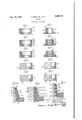
In the drawings, which illustrate embodiments of the device and wherein like reference characters are used to designate like parts Figure 1 is a sectional elevation through a conventional form of cup;
Figure 2 is a sectional elevation through a conventional form of flange packing;
Figures 3 and 6 are sectional elevations of modified forms of cups embodying the invention;
Figure is an enlarged fragmentary sectional elevation through a portion of a cylinder wall and the adjacent portion of the lip and base of the form of cup illustrated in Figura 6, the showing in Figure 5 being that of a cup having the lip under pressure;
Figure 5A is an elevation corresponding to Figure 5 wherein the cup is shown free from pressure, the separation between parts of the cup fiange and adjacent cylinder being shown in an exaggerated manner;
p Figures 4 and 7 are sectlonal elevations of modified forms of flange packings embodying the invention;
Figures 8, 9, 10 and 11 are elevations, partly in section, of modified forms of cups embodying the invention; and
Figure V12 is an elevation corresponding to Figure 5A wherein the lip of the cup is shown of substantially Constant thickness but wherein means is provided to cause the cup to perform under pressure in a manner substantially similar to that shown in Figures 5 and 5A.
The cup shown in Figure 1 consists essentially of the body portion which takes the form of an inwardly directed annular fiange and an annularly disposed lip 22 which may be said to be in the form of an axial, annular fiange. The fiange is designed to press tightly against the adjacent moving part as where this cup is carried by a piston which is movable within a cylinder. When the piston, therefore, is moved, moving the cup, the entire wall or outer working surface 24 of the cup bears against the cylinder wall. The cup is pressed in this position by the hydraulic pressure of the fluid, or the pressure of the gas being pumped, acting on one side of the cup at the same time that there is a vacuum or partial vacuum on the other side of the cup. This tends to more tightly seal the flange 22 against the cylinder wal1 4 Of course, the reverse operation may take place, that is, the packing may be carried by a stationary member and engage a relatively movable member.
The fiange packing illustrated in Figure 2, comprises the body portion 26, taking the form of an outwardly directed annular flange and provided with an axially extending fiange or lip 28 having the working surface 36 thereon. It may be assumed that this packing is held by a stationary member, and a movable member slides internally thereof through the aperture or passage 32. As before, the flange or lip 28 is urged into tight engagement with the movable member by virtue of the hydraulic pressure of the fiuid on one side of the fiange, coupled with the reduced pressure acting on the other side of the flange.
A great many of the packings illustrated in Figures 1 and 2 are formed of leather. The shape of these packings does not lend itself to successful operation of the packings where they are made of plastics, due to the fact that adeq'uate lubrication cannot be attained, which causes excessive wear of the plastic material.
Where it is desired to use a substantially water and oil proof resilient material, the plastic may be used which is preferably chemically incrt to the material With which it comes in contactv Also, under various circumstances materials such as rubber and Synthetic rubber may be used. Certain plastics have been found to be successful where used with the herein contemplated packings, such plastics as enumerated below, being of the non-rigid variety. These plastics are Vinylite, which is a vinyl chloride-acetate base resin;
' Koroseal, which is a polyvinyl Chloride base resin;
Tygon, a modified Vinyl base resin; Styraloy 22, an elastomeric styrene derivative, and Various others, such as vinyl butyral and those of the ethyl cellulose groups. These plastics can be made of Varying degrees of rigidity, depending upon the amount of .plasticizer added to the resin. The more plasticizer that is added, the more flexible and less rigid the material becomes. It is preferable that a permanent plasticizer be used, such as a substantially non-migratory or non-extractible resin or chemical plastlcizer, such as the polyester resinous material known as G- plasticizer sold by Resinous Products & Chemical Co., of Philadelphia, Pennsylvania, because the plastic then retains its characteristics in use, rather than losing some of its 'characteristics as where the plasticizer (Where not permanent) has a greater afiinity for the pumped or adjacent material.
In the packing illustrated in Figure 3, the base 34 is in the form of an annular flange and is provided with the upwardly extending lip 36 which is provided on its working face with continuous ridges or rings 38 which bear against the adjacent cylinder, for example, the ridges being separated by circular depressi-ons 4G thereby forming crests having troughs therebetween. When in operation the hydraulic force within the cup tends to spread or squeeze the fiange 36 against the adjacent working part. However, on
the outside of the cup there is not just the suction pressure, but there is a graduated pressure from ridge to ridge of the pressure within the cup to the suction pressure, the average value of which is one-half the internal pressure within the cup. The force, of course, opposes the internal pressure within the cup.
In Figure 4 the fiange packing comprises the base 42 and the flange or lip 44 provided with the internal rings or ridges 45 adapted to engage the adja'cent working part, the rings or ridges being separated by the depressions' 48. The action of this packing is similar to that descrihed with respect to Figure 3.
The packing illustrated in Figure 6 and the enlarged fragmentary sectional elevations illustrated in Figures 5 and 5A contemplate the body portion 5B and the fiange or lip 52, the fiange or lip being provided with the' spaced working ridges 54 separated by the depressions 56. One more ridge is illustrated in Figures 5 and 5A than is illustrated in Figura 6. In Figure 5 the pressures are shown from ring to ring when the intemal pressure in the cylinder 51 is one hundred pounds per square inch. Adding these pressures together either with the same or more or less rings and dividing by the number of rings, it is readily understandable that the external pressure vpreventing the cup from opening is onehalf the internal pressure. In these forms of construction the wall of the flange is so tapered as to thicken the Wall at the point where there is the greatest difference between the internal and external pressures, that is, adjacent the body portion 5|). This greatl-y stiffens the wall so that after a slight wearing in period, the elasticity of the thicker material will materially support the cup at this point, and consequently all exterior contact points, will bear evenly. In fabricating this packing it is preferably formed so that the external diameter at the extreme lip ridge 54a is greater' than that of the succeeding ridges 54h, 548, and 5M. Preferably, these ridges are formed on a taper so that they contact the cylinder wall as the pressure increases to predetermined amounts.
With the constructions shown in Figures 3 to 12 inclusive, the surface of the working rings are rounded or are disposed in a generally slanting direction facing the moving part. This causes the liquid being pumped to spread into a film between the moving parts for lubricating purposes instead of s'craping the surfaces dry, as would occur in the 'use of the conventional packing shown in Figures 1 and 2.- The formation of this lubricating film is greatly aided by the difference in pressure from ring to ring. Thus it may be said that this cup has hydraulic or forced lubrication. Lubricant under pressure continuously feeds the capillary surfaces between the moving parts so that after a short time the contacting parts are highly polished or glazed.
In the packing illustrated in Figure 7 the base 58 is provided with the lip 5B having the ridges 62 corresponding to the ridges 46 but the wall of the lip is tapered in the same manner and for the same purpose as that illustrated in Figure 6. It is further understood that the configurations hereafter described on the working surfaces of the cups shown in Figures 8 to 11 may be used on the flange packing herein described.
The cups shown in Figures 8 to 11 inclusive consist essentially of the base B4, 66, 68 and 1B provided with the lip 12, 14, 16 and 18, respectively, which may be tapered or not, as desired. The outer working surface of each cup is provided with different configurations of indentations. Figure 8 illustrates staggered and spaced indentations 80 which may be elongated and have rounded ends which may be said to be generally elliptical. The working surface of the cup illustrated in Figure 9 is provided with staggered and spaced, substantially diamond shaped depressions 82. The working surface of the cup illustrated in Figure has substantially circular spaced and: staggeredz dimplesv or depressions 84:.. The working surface of the cup illustrated in. Figure 1,1. is provided with diagonally disposed, intersecting channels 86 which, in effect, form raised', substantially diamond shaped working surfaces 88.
In Figure 12 there is illustrated one form of cup utilizing a lip 90 having a wall of substantially constant thickness. The wall is provided with. the body portion or base 92, said wall having ridges 94', 96, 98 and IUB corresponding to ridges, fia, 5M), 54a and 5M, said ridges being adapted to contact the cylinder wall 102 depending on the predetermined pressure within the cup. In order to obtain the effect of the tapered wall lip of the construction shown in Figures 5 and 5A, Springs IM, Hi', M38 and HO are' disposed within the. wall 9b in substantially the same plane as the adjacent ridges. These Springs are preferably of varying degrees of stiffness, being graduated from the stiffest spring HO to the softest spring IM. Other gradual stiffening means may be used as a leaf spring tapering from the base to the lip or reenforcing means added inside the lip flange.
Thusin the constructions shown the walls of the lips are preferably so shaped and constructed and the material used is such that the effective ridges (or sealing means) of the lip are effective from the lip to the base i. e., the ridges, in order from the lip to the base are effective depending on the built up pressure, the ridge nearest the lip edge being in engagement withv the adjacent working surface (as the cylinders 51 and U12) regardless of the pressure.
With the Shaping of the packing as illustrated or referred to herein, many materials otherwise not desirable or heretofore not successful for use in packings are made available, and other forms of ridges and indentations may be used, providing packing embodying the herein invention, and it is also understood that in addition to packings illustrated, not only U-packing, but other forms as H-packings and special shapes, etc., may be used, and by the use of the term "flange herein it is meant the portion of the packing which is axial with respect to the path of movement or that portion which engages the adjacent working surface. The body portion is that portion other than the flange and in some cases this may be eliminated, providing holding means is otherwise provided in the flange. Further the packing may be made in separate layers lceyed or otherwise fastened together as separate steps. It is to be understood that this application is not to be limited by the exact embodiments of the device shown, which are merely by way of illustration and not Limitation, as various and other forms of the device will, of course, he apparent to those skilled in the art without departing from the spirit of the invention or the scope of the claims.
We claim:
1.. A packing member composed of a non-rigid, non-porous plastic, substantially chemically inert to the substances coming in contact therewith, said packing member having a body portion provided with an axal flange, said flange tapering from said body portion whereby it is thicker adjacent the body portion than at the free edge of the flange, one surface of said fiange being provided with rounded ridges separated by rounded depressions, said ridges and depressions being parallelly arranged circumferentially of said flange and disposed continuously over substantially the entire working surface of said fiange,
the outside diameters of said ridges progressively changing Whereby when the packing member is under a no-load condition only the ridge adjacent the free edge of the fiange engages the working member with which the Working surface of the fiange is adapted to engage.
2. A packing member composed of a non-rigid, non-porous plastic, substantially chemically inert to the substances coming in contact therewith, said packing member having a body portion provided with an axial fiange, said flange being progressively re-enforced from the body portion to adjacent the free edge of the fiange, one surface of said fiange being provided With rounded ridges separated by rounded depressions, said ridges and depressions being parallelly arranged circumferentially of said fiange and disposed continuously over substantially the entire Working surface of said flange, the outside diameters of said ridges progressively changing Whereby when the packing member is under a no-load condition only the ridge adjacent the free edge of the flange engages the Working member With which the Working surface of the flange is adapted to engage.
3. A packing member composed of non-rigid, non-porous material, said packing member having a body portion provided with an axial flange, one surface of said fiange being provided With rounded ridges separated by rounded depressions, said ridges and depressions being parallelly arrangecl circumferentially of said fiange and disposed continuously over substantially the entire Working surface of said flange, the outside diameters of said ridges progressively changing Whereby when the packing member is under a no-lo-ad condition only the ridge adjacent the free edge of the flange engages the Working member With which the Working surface of the flange is adapted to engage.
4. A packing member composed of non-rigid, non-porous material, said packing member having a body portion provided With an axial fiange, one surface of said fiange being provided With rounded ridges separated by rounded depressions, said ridges and depressions being parallelly arranged circumferentially of said fiange and disposed continuously over substantially the entire Working surface of said fiange, the ridge adjacent the free edge of said flange rounding over said edge, and the ridge adjacent the body portion rounding into the bottom surface of said body portion.
5. A packing member composed of non-rigid, non-porous material, said packing member having a body portion provided With an axial flange, one surface of said flange being provided With rounded ridges separated by rounded depressions, said ridges and depressions being parallelly arranged circumferentially of said flange and disposed continuously over substantially the entire Working surface of said flange, the ridge adjacent the free edge of said fiange rounding over said edge, and the ridge adjacent the body portion rounding into the bottom surface of said body portion, the outside diameters of said ridges progressively changing Whereby when the packino' member is under a no-load condition only the ridge adjacent the free edge of the flange engages the working member with which the working surface of the flange is adapted to engage.
6. A packing member composed of a non-rigid, non-porous plastic, substantially chemically inert to the substances coming in contact therewith, said packing member having a body portion provided with an axial flange, said flange being progressively re-enforced from the body portion to adjacent the free edge of the fiange, one surface of said fiange being provided with rounded ridges separated by rounded depressions, said ridges and depressions being parallelly arranged circumferentially of Said fiange and disposed continuously over substantially the entire working surface of said ange, the outside diameters of said ridges progressively changing whereby When the packing member is under a no-load condition only the ridge adjacent the free edge of the flange engages the working member with which the Working surface of the fiange is adapted to engage, the re-enforcement in said fiange comprising resilient means urging said flange in a direction toward the Working member.
7. A packing member composed of a non-rigid, non-porous plastic, substantially chemically inert to the substances coming in contact therewith, said packing member having a body portion provided With an axial fiange, said flange being progressively re-enforced from the body portion to adjacent the free edge of the fiange, one surface of said fiange being provided With rounded ridges separated by rounded depressions, said ridges and depressions being parallelly arranged circumferentially of said fiange and disposed continuously over substantially the entire Working surface of said fiange, the outside diameters of said ridges progressively changing Whereby when the packing member is under a no-load condition only the ridge adjacent the free edge of the fiange engages the Working member With which the Working surface of the fiange is adapted to engage, the reenforcement in said flange comprising resilient means urging the ridges in a direction toward the working member.
CLAYTON MARK, JR. ROBERT HULA. HAROLD J. ALWART.
REFERENCES CITED The following references are of record in the le of this patent:
UNITED STATES PATENTS Number Name Date 1,287,285 Gammeter Dec. 10, 1918 2,036,038 Gottlieb Mar. 31, 1936 2,052,762 Gits Sept. 1, 1936 2,134,302 Haushalter Oct. 25, 1938 2,214,261 Roth Sept. 10, 1940 2,218,638 Christenson Oct. 22, 1940 2,318,757 Christenson May 11, 1943 FOREIGN PATENTS Number Country Date 437,477 Great Britain of 1935
Priority Applications (1)
| Application Number | Priority Date | Filing Date | Title |
|---|---|---|---|
| US564008A US2489715A (en) | 1944-11-18 | 1944-11-18 | Packing |
Applications Claiming Priority (1)
| Application Number | Priority Date | Filing Date | Title |
|---|---|---|---|
| US564008A US2489715A (en) | 1944-11-18 | 1944-11-18 | Packing |
Publications (1)
| Publication Number | Publication Date |
|---|---|
| US2489715A true US2489715A (en) | 1949-11-29 |
Family
ID=24252793
Family Applications (1)
| Application Number | Title | Priority Date | Filing Date |
|---|---|---|---|
| US564008A Expired - Lifetime US2489715A (en) | 1944-11-18 | 1944-11-18 | Packing |
Country Status (1)
| Country | Link |
|---|---|
| US (1) | US2489715A (en) |
Cited By (34)
| Publication number | Priority date | Publication date | Assignee | Title |
|---|---|---|---|---|
| DE922703C (en) * | 1951-02-03 | 1955-01-24 | Hans Kenner | Punching template for punching out zip fastener staples and method and device for producing the same |
| DE974773C (en) * | 1952-11-10 | 1961-04-27 | Stabeg Appbau Ges M B H | Sealing sleeve for pistons pressurized with compressed air |
| US2994571A (en) * | 1957-03-05 | 1961-08-01 | Renault | Piston and rod packings |
| US3055720A (en) * | 1959-06-29 | 1962-09-25 | Bendix Corp | Piston seal construction |
| DE1180202B (en) * | 1961-02-08 | 1964-10-22 | Louis Nogier | Double-acting sealing sleeve for pistons, especially for pistons of plastic syringes |
| US3183009A (en) * | 1963-09-19 | 1965-05-11 | Kunel Heinrich | Grooved packing cup |
| US3243240A (en) * | 1963-01-28 | 1966-03-29 | Clevite Harris Products Inc | Reinforced rubber bushing |
| US3581081A (en) * | 1969-08-11 | 1971-05-25 | Stewart Warner Corp | Automotive license lamp assembly |
| US3708207A (en) * | 1971-04-16 | 1973-01-02 | Dynamic Air | High pressure booster valve |
| FR2138311A1 (en) * | 1971-05-24 | 1973-01-05 | Leduc & Fils Rene | |
| US3792834A (en) * | 1973-01-22 | 1974-02-19 | Sloan Valve Co | Packing seals |
| US3822068A (en) * | 1971-12-31 | 1974-07-02 | Bal Ltd | Packing assemblies |
| US4157835A (en) * | 1975-04-08 | 1979-06-12 | Otto Kahle | Strip seal for stuffing box packing |
| US4355564A (en) * | 1979-03-30 | 1982-10-26 | Atlas Copco Aktiebolag | Pneumatic reciprocating mechanism |
| US4417503A (en) * | 1977-08-20 | 1983-11-29 | Tokico Ltd. | Cylinder device |
| FR2538871A2 (en) * | 1982-12-29 | 1984-07-06 | Leduc Rene Hydro Sa | Improvement to ceiling joints. |
| US4619534A (en) * | 1984-09-12 | 1986-10-28 | Reed Tool Company | Roller cutter drill bit having a texturized seal member |
| US4834037A (en) * | 1987-10-14 | 1989-05-30 | Dana Corporation | Unitary molded plastic valve seal |
| US5492053A (en) * | 1994-12-14 | 1996-02-20 | General Motors Corporation | Bonded piston and seal assembly |
| US6105968A (en) * | 1997-02-24 | 2000-08-22 | Massachusetts Institute Of Technology | Textured seal for reduced wear |
| US6139020A (en) * | 1997-02-24 | 2000-10-31 | Caterpillar Inc. | Textured seal |
| US6619664B1 (en) | 1998-12-18 | 2003-09-16 | Caterpillar Inc | Wear improvement to textured lip seal |
| US20040004326A1 (en) * | 2002-07-02 | 2004-01-08 | Liming Lou | Sealing device and sliding member |
| US6768058B2 (en) | 2002-09-26 | 2004-07-27 | Kirkhill-Ta Co. | Self-sealing grommet assembly |
| US20070235947A1 (en) * | 2004-11-12 | 2007-10-11 | Heiko Meier | Fixable flange gasket |
| US20080246226A1 (en) * | 2007-04-09 | 2008-10-09 | Yoshioki Tomoyasu | Universal shaftseals |
| US20100001026A1 (en) * | 2008-07-02 | 2010-01-07 | Nordson Corporation | Pistons with a lip seal and cartridge systems using such pistons |
| CN101936391A (en) * | 2010-09-18 | 2011-01-05 | 无锡市拓发自控设备有限公司 | Low-friction piston |
| US20120299249A1 (en) * | 2011-05-25 | 2012-11-29 | Denso Corporation | Annular seal member |
| US20130154192A1 (en) * | 2011-12-15 | 2013-06-20 | Trelleborg Sealing Solutions Us, Inc. | Sealing assembly |
| DE102008031813B4 (en) * | 2008-06-26 | 2015-10-22 | Parker Hannifin Gmbh | Sealing arrangement with profile seal |
| US20160068204A1 (en) * | 2014-09-09 | 2016-03-10 | Caterpillar Inc. | Sealing Lip and Seal Assembly for Track Pin Joint Assemblies |
| WO2019016012A1 (en) * | 2017-07-21 | 2019-01-24 | Nidec Gpm Gmbh | SEALING DEVICE WITH CAVITIES |
| WO2023088913A1 (en) * | 2021-11-18 | 2023-05-25 | Trelleborg Sealing Solutions Germany Gmbh | Slotted guide ring with recirculating lubrication and piston-cylinder unit comprising same |
Citations (8)
| Publication number | Priority date | Publication date | Assignee | Title |
|---|---|---|---|---|
| US1287285A (en) * | 1918-04-22 | 1918-12-10 | Goodrich Co B F | Stuffing-box for balloon-cords. |
| GB437477A (en) * | 1934-09-18 | 1935-10-30 | James Corcoran | Improvements in water gauge glass packings |
| US2036038A (en) * | 1934-07-17 | 1936-03-31 | Supco Products Corp | Hydraulic brake system |
| US2052762A (en) * | 1935-12-14 | 1936-09-01 | Remi J Gits | Oil seal |
| US2134302A (en) * | 1936-11-19 | 1938-10-25 | Goodrich Co B F | Gasket |
| US2214261A (en) * | 1938-08-25 | 1940-09-10 | Adam G Roth | Sealing device |
| US2218638A (en) * | 1938-07-21 | 1940-10-22 | Johns Manville | Packing |
| US2318757A (en) * | 1940-03-05 | 1943-05-11 | Johns Manville | Packing |
-
1944
- 1944-11-18 US US564008A patent/US2489715A/en not_active Expired - Lifetime
Patent Citations (8)
| Publication number | Priority date | Publication date | Assignee | Title |
|---|---|---|---|---|
| US1287285A (en) * | 1918-04-22 | 1918-12-10 | Goodrich Co B F | Stuffing-box for balloon-cords. |
| US2036038A (en) * | 1934-07-17 | 1936-03-31 | Supco Products Corp | Hydraulic brake system |
| GB437477A (en) * | 1934-09-18 | 1935-10-30 | James Corcoran | Improvements in water gauge glass packings |
| US2052762A (en) * | 1935-12-14 | 1936-09-01 | Remi J Gits | Oil seal |
| US2134302A (en) * | 1936-11-19 | 1938-10-25 | Goodrich Co B F | Gasket |
| US2218638A (en) * | 1938-07-21 | 1940-10-22 | Johns Manville | Packing |
| US2214261A (en) * | 1938-08-25 | 1940-09-10 | Adam G Roth | Sealing device |
| US2318757A (en) * | 1940-03-05 | 1943-05-11 | Johns Manville | Packing |
Cited By (47)
| Publication number | Priority date | Publication date | Assignee | Title |
|---|---|---|---|---|
| DE922703C (en) * | 1951-02-03 | 1955-01-24 | Hans Kenner | Punching template for punching out zip fastener staples and method and device for producing the same |
| DE974773C (en) * | 1952-11-10 | 1961-04-27 | Stabeg Appbau Ges M B H | Sealing sleeve for pistons pressurized with compressed air |
| US2994571A (en) * | 1957-03-05 | 1961-08-01 | Renault | Piston and rod packings |
| US3055720A (en) * | 1959-06-29 | 1962-09-25 | Bendix Corp | Piston seal construction |
| DE1180202B (en) * | 1961-02-08 | 1964-10-22 | Louis Nogier | Double-acting sealing sleeve for pistons, especially for pistons of plastic syringes |
| US3243240A (en) * | 1963-01-28 | 1966-03-29 | Clevite Harris Products Inc | Reinforced rubber bushing |
| US3183009A (en) * | 1963-09-19 | 1965-05-11 | Kunel Heinrich | Grooved packing cup |
| US3581081A (en) * | 1969-08-11 | 1971-05-25 | Stewart Warner Corp | Automotive license lamp assembly |
| US3708207A (en) * | 1971-04-16 | 1973-01-02 | Dynamic Air | High pressure booster valve |
| FR2138311A1 (en) * | 1971-05-24 | 1973-01-05 | Leduc & Fils Rene | |
| US3822068A (en) * | 1971-12-31 | 1974-07-02 | Bal Ltd | Packing assemblies |
| US3792834A (en) * | 1973-01-22 | 1974-02-19 | Sloan Valve Co | Packing seals |
| US4157835A (en) * | 1975-04-08 | 1979-06-12 | Otto Kahle | Strip seal for stuffing box packing |
| US4417503A (en) * | 1977-08-20 | 1983-11-29 | Tokico Ltd. | Cylinder device |
| US4355564A (en) * | 1979-03-30 | 1982-10-26 | Atlas Copco Aktiebolag | Pneumatic reciprocating mechanism |
| FR2538871A2 (en) * | 1982-12-29 | 1984-07-06 | Leduc Rene Hydro Sa | Improvement to ceiling joints. |
| US4619534A (en) * | 1984-09-12 | 1986-10-28 | Reed Tool Company | Roller cutter drill bit having a texturized seal member |
| US4834037A (en) * | 1987-10-14 | 1989-05-30 | Dana Corporation | Unitary molded plastic valve seal |
| US5492053A (en) * | 1994-12-14 | 1996-02-20 | General Motors Corporation | Bonded piston and seal assembly |
| US6105968A (en) * | 1997-02-24 | 2000-08-22 | Massachusetts Institute Of Technology | Textured seal for reduced wear |
| US6139020A (en) * | 1997-02-24 | 2000-10-31 | Caterpillar Inc. | Textured seal |
| US7284758B1 (en) | 1997-02-24 | 2007-10-23 | Massachusetts Institute Of Technology | Textured seal for reduced wear |
| US6619664B1 (en) | 1998-12-18 | 2003-09-16 | Caterpillar Inc | Wear improvement to textured lip seal |
| US20040004326A1 (en) * | 2002-07-02 | 2004-01-08 | Liming Lou | Sealing device and sliding member |
| US7156399B2 (en) | 2002-07-02 | 2007-01-02 | Koyo Seiko Co., Ltd. | Sealing device and sliding member |
| EP1378691A3 (en) * | 2002-07-02 | 2004-04-21 | Koyo Seiko Co., Ltd. | Sealing device and sliding member |
| EP1962002A2 (en) | 2002-07-02 | 2008-08-27 | JTEKT Corporation | Sealing device and sliding member |
| EP1962002A3 (en) * | 2002-07-02 | 2008-09-03 | JTEKT Corporation | Sealing device and sliding member |
| US6768058B2 (en) | 2002-09-26 | 2004-07-27 | Kirkhill-Ta Co. | Self-sealing grommet assembly |
| US20070235947A1 (en) * | 2004-11-12 | 2007-10-11 | Heiko Meier | Fixable flange gasket |
| US20080246226A1 (en) * | 2007-04-09 | 2008-10-09 | Yoshioki Tomoyasu | Universal shaftseals |
| DE102008031813B4 (en) * | 2008-06-26 | 2015-10-22 | Parker Hannifin Gmbh | Sealing arrangement with profile seal |
| EP2921426A1 (en) * | 2008-07-02 | 2015-09-23 | Nordson Corporation | Pistons with a lip seal and cartridge systems using such pistons |
| EP2143662A1 (en) * | 2008-07-02 | 2010-01-13 | Nordson Corporation | Pistons with a lip seal and cartridge systems using such pistons |
| US8235255B2 (en) | 2008-07-02 | 2012-08-07 | Nordson Corporation | Pistons with a lip seal and cartridge systems using such pistons |
| US20100001026A1 (en) * | 2008-07-02 | 2010-01-07 | Nordson Corporation | Pistons with a lip seal and cartridge systems using such pistons |
| CN101936391B (en) * | 2010-09-18 | 2012-07-04 | 无锡市拓发自控设备有限公司 | Low-friction piston |
| CN101936391A (en) * | 2010-09-18 | 2011-01-05 | 无锡市拓发自控设备有限公司 | Low-friction piston |
| US20120299249A1 (en) * | 2011-05-25 | 2012-11-29 | Denso Corporation | Annular seal member |
| US8814170B2 (en) * | 2011-05-25 | 2014-08-26 | Advics Co., Ltd. | Annular seal member |
| US20130154192A1 (en) * | 2011-12-15 | 2013-06-20 | Trelleborg Sealing Solutions Us, Inc. | Sealing assembly |
| US20160068204A1 (en) * | 2014-09-09 | 2016-03-10 | Caterpillar Inc. | Sealing Lip and Seal Assembly for Track Pin Joint Assemblies |
| WO2019016012A1 (en) * | 2017-07-21 | 2019-01-24 | Nidec Gpm Gmbh | SEALING DEVICE WITH CAVITIES |
| CN110914580A (en) * | 2017-07-21 | 2020-03-24 | 尼得科Gpm有限公司 | Sealing device with chamber |
| WO2023088913A1 (en) * | 2021-11-18 | 2023-05-25 | Trelleborg Sealing Solutions Germany Gmbh | Slotted guide ring with recirculating lubrication and piston-cylinder unit comprising same |
| TWI842165B (en) * | 2021-11-18 | 2024-05-11 | 德商特瑞堡密封系統德國有限公司 | Slotted guide ring with circulation lubrication and piston-cylinder unit having such a slotted guide ring |
| US12398804B2 (en) | 2021-11-18 | 2025-08-26 | Trelleborg Sealing Solutions Germany Gmbh | Slotted guide ring with recirculating lubrication and piston-cylinder unit |
Similar Documents
| Publication | Publication Date | Title |
|---|---|---|
| US2489715A (en) | Packing | |
| US4179131A (en) | Seal arrangements | |
| US2521248A (en) | Packing means | |
| US3271038A (en) | Sealing devices | |
| US3785660A (en) | Seal | |
| US4568092A (en) | Lip seal | |
| US3920252A (en) | Dynamic seal for double-acting piston | |
| US5524905A (en) | Sealing assembly with T-shaped seal ring and anti-extrusion rings | |
| US3822890A (en) | Bearing seals | |
| US3268235A (en) | Piston accumulator seal | |
| CN101535692B (en) | Oil seal for reciprocation motion | |
| US2465175A (en) | Double wall washer or packing cup | |
| US6340161B1 (en) | Machinery seal | |
| JPH07158746A (en) | Rod seal or piston seal | |
| USRE24440E (en) | Groen | |
| US2392182A (en) | Piston construction | |
| US4749202A (en) | Sealing and guide unit for pistons in general | |
| US2512098A (en) | Sealing packing | |
| EP0889265B1 (en) | Rod and piston sealing | |
| US2310405A (en) | Oil seal | |
| US3653672A (en) | Seal ring | |
| US2466428A (en) | Piston seal | |
| US3942808A (en) | Piston ring assembly | |
| US2360735A (en) | Laminated sealing ring | |
| US4161320A (en) | Resilient packing |