US2489583A - Method of cutting blanks from thin sheet or strip material - Google Patents
Method of cutting blanks from thin sheet or strip material Download PDFInfo
- Publication number
- US2489583A US2489583A US4313A US431348A US2489583A US 2489583 A US2489583 A US 2489583A US 4313 A US4313 A US 4313A US 431348 A US431348 A US 431348A US 2489583 A US2489583 A US 2489583A
- Authority
- US
- United States
- Prior art keywords
- dies
- die
- cuts
- sheet
- cutting
- Prior art date
- Legal status (The legal status is an assumption and is not a legal conclusion. Google has not performed a legal analysis and makes no representation as to the accuracy of the status listed.)
- Expired - Lifetime
Links
- 238000005520 cutting process Methods 0.000 title description 52
- 239000000463 material Substances 0.000 title description 47
- 238000000034 method Methods 0.000 title description 30
- 238000004519 manufacturing process Methods 0.000 description 14
- 239000002699 waste material Substances 0.000 description 8
- 238000010586 diagram Methods 0.000 description 7
- 239000002184 metal Substances 0.000 description 4
- 230000007246 mechanism Effects 0.000 description 3
- 238000010008 shearing Methods 0.000 description 2
- 241001125046 Sardina pilchardus Species 0.000 description 1
- 238000010924 continuous production Methods 0.000 description 1
- 235000013372 meat Nutrition 0.000 description 1
- 235000019512 sardine Nutrition 0.000 description 1
- 239000005028 tinplate Substances 0.000 description 1
Images
Classifications
-
- B—PERFORMING OPERATIONS; TRANSPORTING
- B21—MECHANICAL METAL-WORKING WITHOUT ESSENTIALLY REMOVING MATERIAL; PUNCHING METAL
- B21D—WORKING OR PROCESSING OF SHEET METAL OR METAL TUBES, RODS OR PROFILES WITHOUT ESSENTIALLY REMOVING MATERIAL; PUNCHING METAL
- B21D28/00—Shaping by press-cutting; Perforating
- B21D28/02—Punching blanks or articles with or without obtaining scrap; Notching
- B21D28/06—Making more than one part out of the same blank; Scrapless working
-
- Y—GENERAL TAGGING OF NEW TECHNOLOGICAL DEVELOPMENTS; GENERAL TAGGING OF CROSS-SECTIONAL TECHNOLOGIES SPANNING OVER SEVERAL SECTIONS OF THE IPC; TECHNICAL SUBJECTS COVERED BY FORMER USPC CROSS-REFERENCE ART COLLECTIONS [XRACs] AND DIGESTS
- Y10—TECHNICAL SUBJECTS COVERED BY FORMER USPC
- Y10T—TECHNICAL SUBJECTS COVERED BY FORMER US CLASSIFICATION
- Y10T83/00—Cutting
- Y10T83/04—Processes
- Y10T83/0524—Plural cutting steps
- Y10T83/0577—Repetitive blanking
Definitions
- invention relates to methods of cutting blanks from thin sheet or strip :materiaLparticularly along the general lines set forth in .my-pending application for means and methods for butting blanks from thin sheets .or strips .of metal filed November 7, 1945, :Serial No. 627,142.
- dies are .so mounted .line that whether a single row :of dies 45 so :mounted or multiple rows of dies in parallel relationship to each other are so mounted, the .leading die, in the case of single vmows uor the leading die in each row, in the case of multiple rows .in parallel relationship to each nthi-zer, straddles or rstraddle over one or more potential blank spaces at eachfeed stroke and Lmake its or their productive cuts in the area of the sheet or strip just beyond the :area thus straddled; .and the following die in longitudinal relationship .to the direction of the feed travel, if double dies in longitudinal line are employed, .or the following dies in longitudinal relationship -to the direction of the feed travel if more than two dies in each longitudinal line are employed, straddle over the blanked out portion of the .sheet or :strip which has been worked by the dies preceding it-or them and make their productive cuts .-in the .un
- Another advantage of the invention wherein the .dies are to be mounted is that when two .dies .are thus mounted in line, or in each row of parallel 'lines, as above stated, their mounting may be such that the leading die in each row .flongitudinal of the feed stroke makes two or .more ,die cuts in the straddled space before the .following'die in thesame row makes its first die cut in that row, with that sequence being maintained until the entire sheet orl-strip is worked.
- Another advantage :of spacing the dies .to provide fora plurality of :cutstbefore the next .succeeding cut is made so that feeding, stops and registering mechanisms operating in openings 'cut in the :sheet by the leading :dies, the space also provides room for blankideliverychutes and by so spacing'the succeeding dies of each series such chutes for receiving blanks from each die successively or sets of dies may be positioned immediately following each die or set of dies ior receiving and carrying the blanks laterally out from the path of the cutters to a suitable receiver and further feeding, stopping, registering and holding'mechanism as may be desired may also be positioned between each of the successiVe dies or sets of dies and beyond the last 'cuttingdie or set of dies in the'series.
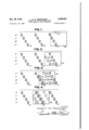
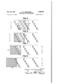
- Figs. 1 *to 8 inclusive are diagrammatic views showing the manner in which stock such as tin plate, 'is'fed to dies during the steps taken'tocut 'aplurality of rows of blanks in accordance with the present invention.
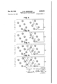
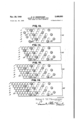
- Figs. "'9 to 16 "inclusive are similar diagrammatic views of a modified arrangement for carrying out the process in accordance with this invention.
- the first eight figures of the drawings illustrate the manner in which one process in accordance with this invention is applied in actual practice in the production of oblong can ends, square package ends which have rounded corners, specialty package ends, sardine cans and can ends, meat can ends, and other similar shapes, or shapes which are not round or disc like.
- the process is shown as applied to a plurality of rows with the die of the first row in an advanced position by the amount of a blank end plus the 3 waste thread and each of the succeeding rows in a similar advanced position with respect to the row that follows.
- the second group of figures, 9 to 16 inclusive illustrate one manner in which the process can be applied in actual practice in the production of round can ends, of bottle caps, and of any similar discs of any kind.
- FIGs. 1 to 8 show how the series of sketches numbered 1 to l2 inclusive show how one of the die layouts which employ a method generally of the type covered by my copending application may be used to great advantage in the manufacture of oblong can ends by either gang die production or multiple die production with either separate die or dies mounted in separate 7 presses.
- Altho triple dies H, !8 and !9 in line in four rows A, B, C and D longitudinal to the direction of the feed travel are shown it is to be understood that more or less than that number of dies may be more or less similarly mounted without in any way departing from the spirit of this invention.
- Fig. 1 of these diagrams shows the first sheet 20 of a stack of sheets as it is fed into position for the first die cut of a series of die cuts.
- Fig. 2 shows the same sheet 20 properly positioned for the second die cut.
- the feed has moved it along a distance equivalent to three die cuts plus the width of the necessary threads between the blanks formed by said die cuts.
- the three blank spaces ITA, H 1B and HG left in the sheet by the first die cut are, in consequence, shown as being three spaces to the left of the present position, with two potential spaces between them and the present position having been straddled and still remaining uncut.
- Fig. 3 shows the same sheet 2!! advanced to properly position it for the third die cut.
- the feed has moved it forward again the same distance.
- the three spaces HA, HE and HG left in the sheet when the first die cut was made are shown as in Fig. 2 and also the four spaces HA2, I 132, N02 and l 1D2 left when the second die cut was made are now shown.
- the first two dies ill of the second row of dies transversely of the direction of feed travel now make their first die cut and the advantage of the straddle cut begins to be plainly apparent.
- Fig. 4. shows the same sheet 20 properly positioned for the fourth die cut.
- the feed has moved it forward again the same distance.
- the spaces left in the sheet when all preceding die cuts were made are clearly shown.
- All four of the second row of dies [8 which are mounted transversely of the direction of the feed travel will make cuts when the sheet is in this position and. all four of the first row of dies which are so mounted are shown as making unproductive cuts.
- the die cutting is continuous without having to provide for such separate sheet feeding.
- Fig. 5 shows the same sheet 20 similarly positioned for the fifth die out. It has been moved forward again the same distance. The spaces left in the sheet when all preceding die cuts were made show as before. All four of the second row of dies which are mounted transversely of the direction of the feed travel are shown making cuts and the first die IQ of th third row so mounted has come into action on this sheet for the first time. Altho the first row of dies i! so mounted is shown making unproductive cuts, in actual practice as referred to above they will all be making productive cuts on the following sheet if sheets are employed, while if continuous strip is employed they will of course be in continuous production.
- Fig. 6 shows sheet 20 properly positioned for the sixth die cut. It has been moved again the The position of the last row of dies 19 which are mounted transversely of the direction of the feed travel and spaces left in the sheet by the preceding die cuts clearly show that all remaining potential blanks will be worked by this last row of dies following the next two feed strokes as shown in Figs. 7 and 8. The great conservation of both metal and machine production inherent in this straddle cut mountin of dies in relation to the feed movement has now been made clear.
- Figures 9 to 16 illustrate a modified arrangement-of the dies which may be .usedtogreat advantage in themanufacture of roundcanendsby either gang .die production .or multiple -die .prozduction with .either separate .dies or separate irowsaof dies mounted in separate presses. .Altho the method can be ,well illustrated by employing .twelve dies .in these diagrams more .or .less than that number of ..dies (may he :more or less. similarly mounted without in .any way departing fromthe spirit of this invention.
- altho production irom continuous strip is being shown production from sheets with either scroll out ends .or preferably stagger .cnt ends such .as covered in my Patent No. 2,335,292, can be done to almost .as good advantage and .should be employed in .all cases when sheets must'be 'lithographed before being worked .up, as for instance in the manufacture of bottle caps.
- Altho in this series of diagrams I am showing how the ends of a continuous strip .122 canbe handledxto advantage'it is not necessary or vital to theproper tunctioning :of my method to have the strip enter or leave the "lines in any particular manner and altho I am showing double dies 23' and 2G in line in each row longitudinal of the direction of feed travel and showing them straddling three times before the second die in that same row makes its first cut it is to be understood that triple or above triple dies in line may be employed and any distance may be straddled which brings about the proper sequence of operation in accordance with my invention herein.
- Fig. 9 shows the leading edge of-a long and 'wid'eco'il of continuous strip-metal 22 which has been unco'iled, flattened andsidetrimmed to close accuracy by means Well known in the industry, and has had "its leading end 25 sheared to :an -:angle corresponding to the angle :of 'the die "mounting employed.
- the operator first positions the leading end of the strip approximately as shown in Fig.
- Fig. 211 shows the strip moved along the same distance by :another feed stroke, and positioned :means and .stopszmay all be employed vnow off-the openings made in the sheet byth nmc fiing die cuts.
- .iFig. .LZ- shows the strip again moved along ⁇ same distance and positioned for the fourth out. While in this position the :first row iOf dies cuts out what will the -.approximate1y a half can end, which the :operator sends to "waste. .Qf :oourse :no more waste except what is termed sin -:lt'he industry last waste scrap, will be .1051; until :the entire strip is worked iup.
- Fig. shows the ;st1'ip again :moved :along the same distance and positioned :for the fifth :die out.
- Fig. M shows the strip again moved along the :same distance and positioned for .the sixth die out and iEigs. -15 and 16 show the results :of the succeeding two operations illustrating the-com-- pletely punched portion-of the strip as it passes :tl're-flnaL-row :of dies if the strip were "to remain extending after such operations. .As positioned :in Eli-g.
- shearing at @either end :iszoptional is (not vital to this invention, and may have any other form of shearing :sub- .stituted, or another long strip "may be welded .to this firstone if desired.
- Waste scrap resulting from this operation may .be coiled .after all die cuts are made and .as they .are being vmade or it may be chopped up into small segments by scrap choppers and carried away by conveyors, in accordance with practice as set forth in .my earlier copending application referred to here'inbefore.
- the strip is prevented from going too .iar, -.brought along ,just far enough, and is located to high accuracy by registration devices, functioning for the .first time inside of the blank spaces in the strip which are now .for the .first time made available thru the adoption of this method.
- the method of cutting can end blanks from sheet material providing a plurality of potential can end producing spaces in side by side relationship in the sheet material, comprising feeding the sheet material, step by step, a distance at each step equal to the distance between the center lines of three potential can end producing spaces, to a pair of simultaneously operating dies spaced apart longitudinally of the path of travel of the sheet material a distance equal to the distance between the center lines of eight potential can end producing spaces.
- the method of cutting can end blanks from sheet material providing a plurality of potential can end producing spaces in side by side relationship in the sheet material, comprising feeding the sheet material, step by step, a distance at each step equal to the distance between the center lines of three potential can end producing spaces, to three simultaneously operating dies spaced apart longitudinally of the path of travel of the sheet material a distance equal to the distance between the center lines of eight potential can end producing spaces.
Landscapes
- Engineering & Computer Science (AREA)
- Mechanical Engineering (AREA)
- Perforating, Stamping-Out Or Severing By Means Other Than Cutting (AREA)
Description
Nov. 29, 1949 w, MESSENGER 2,489,583
, METHOD OF CUTTING BLANKS FROM THIN SHEET OR STRIP MATERIAL Filed Jan. 26, 1948 4 Sheets-Sheet 1 Fig. 1
\ b1 db swam lNVENTOR.
Huber-t- W Nessa-1g ET.
ATTORNEYS.
Nov. 29, 1949 R. w. MESSENGER 2,489,583
METHOD OF CUTTING BLANKS FROM THIN SHEET OR STRIP MATERIAL Filed Jan. 26, 1948 4 Sheets-Sheet 2 OUOUUOOO Q lNVENTOR.
Ppherr W EESEH v ATTORNEYS.
Nov. 29, 1949 R. w. MESSENGER 2,489,583 METHOD OF CUTTING BLANKS FROM THIN SHEET QR STRIP MATERIAL 4 Sheets-Sheet 3 Filed Jan. 26, 1948 INVENTOR. W ME 5 5 2% ATTORNEYS.
R. w. MESSENGER UTTING 0R STR C BLANKS T IP MATE Nov.2 9,1949
THOD 0F HIN SHEE Filed Jan. 26, 1948 4 Sheets-Sheet 4 FIG. 16.
. M w W 0 0% 0@0@00 M C 0 1% 0 nfl .m 0 0 m m m owowo 0 0 0 0 wmo mm o 0. a
Patented Nov. 29, 1949 METHOD OF' CUTTING BLANKS FROM THIN SHEET OR 'STRIFMATERIAL Robert W. Messenger, Salisbury, Md.; .Zilda Minerva Messengerand William Ashley Messenger executors of said Robert W. .Messenger, de-
ceased ApplicationJanuary 26, '1948,:Serial:No. 4;313
'14 Claims.
:invention relates to methods of cutting blanks from thin sheet or strip :materiaLparticularly along the general lines set forth in .my-pending application for means and methods for butting blanks from thin sheets .or strips .of metal filed November 7, 1945, :Serial No. 627,142.
In accordance with this .invention dies are .so mounted .line that whether a single row :of dies 45 so :mounted or multiple rows of dies in parallel relationship to each other are so mounted, the .leading die, in the case of single vmows uor the leading die in each row, in the case of multiple rows .in parallel relationship to each nthi-zer, straddles or rstraddle over one or more potential blank spaces at eachfeed stroke and Lmake its or their productive cuts in the area of the sheet or strip just beyond the :area thus straddled; .and the following die in longitudinal relationship .to the direction of the feed travel, if double dies in longitudinal line are employed, .or the following dies in longitudinal relationship -to the direction of the feed travel if more than two dies in each longitudinal line are employed, straddle over the blanked out portion of the .sheet or :strip which has been worked by the dies preceding it-or them and make their productive cuts .-in the .unworked area of the sheet or .strip which .has been straddled by the first die, when double dies are employed in longitudinal line, or .by all preceding dies, when lmore than two .dies in longitudinal line are employed; and this sequence -of die strokes is made until the entire sheet or strip is worked up, in co-ordination with the feed strokes which move the sheet or strip being worked .forward a distance equivalent to the longitudinal distance represented by two die cuts plus the .necessary threads between the blanks formed by said die outs, in the case of double dies in line, .of three die cuts plus the necessary threads between the blanks formed by .said -.die cuts, in the case of triple .dies in line, of :iour-die .cuts plus the necessary threads between the blanks formed by said ,die cuts, in the .case of quadruple (dies in line, of "five die cuts plus the necessary threads between the blanks formed by said die cuts, .in the case of quintuple diesin line, and so on up into multiple die mounting xo'f this lkindeand .for this purpose.
Another advantage of the invention wherein the .dies are to be mounted is that when two .dies .are thus mounted in line, or in each row of parallel 'lines, as above stated, their mounting may be such that the leading die in each row .flongitudinal of the feed stroke makes two or .more ,die cuts in the straddled space before the .following'die in thesame row makes its first die cut in that row, with that sequence being maintained until the entire sheet orl-strip is worked. .Similarly, that when triple dies in .line, quadruple dies in line, quintuple dies in line, .or multiple .dies above 'quintuple dies in .line are so mounted, their mounting may be such that the leading die in each row'longitudinal of the feed stroke makestwoor more die cuts in the straddled space before the first following die in the same row longitudinal 10f the feedstrokemakes its first productive cut, and it in turn and if desired also makes two or more die cuts before :the next .die in :line :makes its first productive die :cut, and so on up.
further advantage of such arrangement :re-
sides :in the fact that when dies :areso mounted feeding means :to .move the sheet :or strip :for-
ward :to the vnext location, stops to prevent the -the :openings cut into the sheet 501 strip Lby'the leading dies "in making their productive die :cuts.
Another advantage :of spacing the dies .to provide fora plurality of :cutstbefore the next .succeeding cut is made so that feeding, stops and registering mechanisms operating in openings 'cut in the :sheet by the leading :dies, the space also provides room for blankideliverychutes and by so spacing'the succeeding dies of each series such chutes for receiving blanks from each die successively or sets of dies may be positioned immediately following each die or set of dies ior receiving and carrying the blanks laterally out from the path of the cutters to a suitable receiver and further feeding, stopping, registering and holding'mechanism as may be desired may also be positioned between each of the successiVe dies or sets of dies and beyond the last 'cuttingdie or set of dies in the'series.
-Other objects and advantages-of the invention will appear in the following detailed description, "taken in connection with the accompanying drawings, forming a part of this specification and in which drawings:
Figs. 1 *to 8 inclusive are diagrammatic views showing the manner in which stock such as tin plate, 'is'fed to dies during the steps taken'tocut 'aplurality of rows of blanks in accordance with the present invention, and
Figs. "'9 to 16 "inclusive are similar diagrammatic views of a modified arrangement for carrying out the process in accordance with this invention.
Referring to the drawings in general the first eight figures of the drawings illustrate the manner in which one process in accordance with this invention is applied in actual practice in the production of oblong can ends, square package ends which have rounded corners, specialty package ends, sardine cans and can ends, meat can ends, and other similar shapes, or shapes which are not round or disc like. As illustrated the process is shown as applied to a plurality of rows with the die of the first row in an advanced position by the amount of a blank end plus the 3 waste thread and each of the succeeding rows in a similar advanced position with respect to the row that follows. The second group of figures, 9 to 16 inclusive, illustrate one manner in which the process can be applied in actual practice in the production of round can ends, of bottle caps, and of any similar discs of any kind. By this arrangement for cutting discs the dies in the successive rows are in staggered relation and the leading die of each row is arranged to make three stanipings before the next die, in the row of two dies as shown, produces its stamping. For cutting circular discs the arrangement of the forduced by the leading die in the row and the next succeeding die in the same row, instead of such arrangement as disclosed in my copending application heretofore referred to.
In accordance with the process as disclosed in Figs. 1 to 8 these diagrams show how the series of sketches numbered 1 to l2 inclusive show how one of the die layouts which employ a method generally of the type covered by my copending application may be used to great advantage in the manufacture of oblong can ends by either gang die production or multiple die production with either separate die or dies mounted in separate 7 presses. Altho triple dies H, !8 and !9 in line in four rows A, B, C and D longitudinal to the direction of the feed travel are shown it is to be understood that more or less than that number of dies may be more or less similarly mounted without in any way departing from the spirit of this invention. Also, altho production from sheets 20 only four blanks wide and eight blanks long is shown in these figures it is to be understood that sheets any width desired and any length desired may instead be employed, and that up to reasonable widths and reasonable lengths great economy of production will be gained by employing much larger sheets. Also, it is to be further understood that continuous strip can be employed to even greater advantage than sheets with this type of die layout and that quadruple, quintuple and greater multiple dies in line may also be advantageously employed when dies are mounted according to this method.
Fig. 1 of these diagrams shows the first sheet 20 of a stack of sheets as it is fed into position for the first die cut of a series of die cuts. The
dicated by the arrow 2|.
. same distance.
Fig. 2 shows the same sheet 20 properly positioned for the second die cut. The feed has moved it along a distance equivalent to three die cuts plus the width of the necessary threads between the blanks formed by said die cuts. The three blank spaces ITA, H 1B and HG left in the sheet by the first die cut are, in consequence, shown as being three spaces to the left of the present position, with two potential spaces between them and the present position having been straddled and still remaining uncut.
Fig. 3 shows the same sheet 2!! advanced to properly position it for the third die cut. The feed has moved it forward again the same distance. The three spaces HA, HE and HG left in the sheet when the first die cut was made are shown as in Fig. 2 and also the four spaces HA2, I 132, N02 and l 1D2 left when the second die cut was made are now shown. The first two dies ill of the second row of dies transversely of the direction of feed travel now make their first die cut and the advantage of the straddle cut begins to be plainly apparent.
Fig. 4. shows the same sheet 20 properly positioned for the fourth die cut. The feed has moved it forward again the same distance. The spaces left in the sheet when all preceding die cuts were made are clearly shown. All four of the second row of dies [8 which are mounted transversely of the direction of the feed travel will make cuts when the sheet is in this position and. all four of the first row of dies which are so mounted are shown as making unproductive cuts. In actual practice, however, when sheets such as sheet 20 are used, the next sheet will follow this one with only one potential blank between its leading edge and the trailing edge of this sheet as shown in Fig. 1. However using strip material the die cutting is continuous without having to provide for such separate sheet feeding.
Fig. 5 shows the same sheet 20 similarly positioned for the fifth die out. It has been moved forward again the same distance. The spaces left in the sheet when all preceding die cuts were made show as before. All four of the second row of dies which are mounted transversely of the direction of the feed travel are shown making cuts and the first die IQ of th third row so mounted has come into action on this sheet for the first time. Altho the first row of dies i! so mounted is shown making unproductive cuts, in actual practice as referred to above they will all be making productive cuts on the following sheet if sheets are employed, while if continuous strip is employed they will of course be in continuous production.
Fig. 6 shows sheet 20 properly positioned for the sixth die cut. It has been moved again the The position of the last row of dies 19 which are mounted transversely of the direction of the feed travel and spaces left in the sheet by the preceding die cuts clearly show that all remaining potential blanks will be worked by this last row of dies following the next two feed strokes as shown in Figs. 7 and 8. The great conservation of both metal and machine production inherent in this straddle cut mountin of dies in relation to the feed movement has now been made clear.
It will be seen that the operation of dies IS in rows C and D on sheet 2!! in Fig. 8 cuts the last potential blanks from this sheet and following this operation by dies l9 sheet 20 may be cut up or otherwise ejected as scrap. In showing the oneness 'diesand their cuts "in these diagrams itiisrobnions for purpose of illustration, 'thezblank spaces 381118 :shown at greater trelative distanoesiazpart than :practice for the required sthread :space which is relatively narrow. it 'is also clear that the process may hotter be applied to continuous strip material than to sheets 20 having a length of {eight potential blank widths with the necessity tor .feeding the next succeeding sheet a potential .hla-n'k space hehind the end of the :sheet '21! passing thruthe dies.
Figures 9 to 16 illustrate a modified arrangement-of the dies which may be .usedtogreat advantage in themanufacture of roundcanendsby either gang .die production .or multiple -die .prozduction with .either separate .dies or separate irowsaof dies mounted in separate presses. .Altho the method can be ,well illustrated by employing .twelve dies .in these diagrams more .or .less than that number of ..dies (may he :more or less. similarly mounted without in .any way departing fromthe spirit of this invention. Also, altho production irom continuous strip is being shown production from sheets with either scroll out ends .or preferably stagger .cnt ends such .as covered in my Patent No. 2,335,292, can be done to almost .as good advantage and .should be employed in .all cases when sheets must'be 'lithographed before being worked .up, as for instance in the manufacture of bottle caps. Altho .in this series of diagrams I am showing how the ends of a continuous strip .122 canbe handledxto advantage'it is not necessary or vital to theproper tunctioning :of my method to have the strip enter or leave the "lines in any particular manner and altho I am showing double dies 23' and 2G in line in each row longitudinal of the direction of feed travel and showing them straddling three times before the second die in that same row makes its first cut it is to be understood that triple or above triple dies in line may be employed and any distance may be straddled which brings about the proper sequence of operation in accordance with my invention herein.
Fig. 9 shows the leading edge of-a long and 'wid'eco'il of continuous strip-metal 22 which has been unco'iled, flattened andsidetrimmed to close accuracy by means Well known in the industry, and has had "its leading end 25 sheared to :an -:angle corresponding to the angle :of 'the die "mounting employed. A ltho the :diagrams :are planviews it is to he understood that :press beds 'are customarily inclined to .a high angle :and that any angle desired may be employed. The operator :first positions the leading end of the strip approximately as shown in Fig. i9 without attempting to reach high accuracy in this posttioning for the first out by the :advanced dies 123 in rows '3, D and :Fig. 10 shows the stripafter :itiha's *Joeen'moved aalon'g, Ifromlright :to :left, .a distance equivalentto the diameter of two can ends plus the width act the necessary threads between them, "and .has been located exactly the new :position. While in this position, and with all dies functioning simultaneously, the second "row A, C, Epf dies'23 puts out 'what-will be approximately 'aihalf can end each, which the operator sends to waste. These ilcalf can end cuts are in advance of the the firstcuts made by the dieswith sheet 22 in :the position shown in Fig. 9.
Fig. 211 shows the strip moved along the same distance by :another feed stroke, and positioned :means and .stopszmay all be employed vnow off-the openings made in the sheet byth nmc fiing die cuts.
.iFig. .LZ-shows the strip again moved along {same distance and positioned for the fourth out. While in this position the :first row iOf dies cuts out what will the -.approximate1y a half can end, which the :operator sends to "waste. .Qf :oourse :no more waste except what is termed sin -:lt'he industry last waste scrap, will be .1051; until :the entire strip is worked iup. This results 1111158 'oonservation of metal far exceeding any present -day practice while at the .same time straddle mounting of the dies ibrings about a rate of :out- ;put per machine which .also far exceeds may present 'day practice.
Fig. shows the ;st1'ip again :moved :along the same distance and positioned :for the fifth :die out.
Fig. Mshows the strip again moved along the :same distance and positioned for .the sixth die out and iEigs. -15 and 16 show the results :of the succeeding two operations illustrating the-com-- pletely punched portion-of the strip as it passes :tl're-flnaL-row :of dies if the strip were "to remain extending after such operations. .As positioned :in Eli-g. :14 (as well as succeeding positions of the .strip.) this die .out brings the second :row of :dies 724 into production ,for the :first time, --and .from this point until the trailing end of the strip-is meachedall diesare in full production all aOf *the time. In order that waste -:at the trailin aend'rof the strip :may :be minimized that end-.may he :shear-ed diagonally in the same manner that the leading edge was sheared, and at a point which will ensure as little loss from waste as occurred at the leading end. Such shearing at @either end :iszoptional, however, is (not vital to this invention, and may have any other form of shearing :sub- .stituted, or another long strip "may be welded .to this firstone if desired.
Waste scrap resulting from this operation may .be coiled .after all die cuts are made and .as they .are being vmade or it may be chopped up into small segments by scrap choppers and carried away by conveyors, in accordance with practice as set forth in .my earlier copending application referred to here'inbefore.
.Itwill be seen thatin accordance with this .arrangement 'inwhich the strip cut by ithe'leading die of the row with three blank openingsin ad- 'vance of the second die of two dies 'in the row and in the arrangement illustrated in the first group of diagrams *two such openings are pro- 'duced in advance of the second die of a row of three dies. By such arrangemen't'it-can be plainly :seen that theoperator desires .to employeither primary "ifeeding :means .or auxiliary feeding oneans inside of the openings :in the .strip which are made .by the first dies to vzmake their cutsrows which are longitudinal of the strip, and/or locating means in said openings, .and/or .stops'in .said .openings, they may .be .so located .With .im- :portant added advantages resulting.
By such .f-oeding, stopping and registering mechanisms the strip is prevented from going too .iar, -.brought along ,just far enough, and is located to high accuracy by registration devices, functioning for the .first time inside of the blank spaces in the strip which are now .for the .first time made available thru the adoption of this method.
I claim:
1. In the method "of cutting :a plurality of for the third I cu -Feedlirlg s, ca *fliblanks from sheet material providing blank "producing spaces, with a plurality of die cutting elements in alignment having an interval between first and second dies to provide for a plurality of cuts between the first and second dies before the second die makes its first out, which consists in successively feeding the sheet material by intervals equal to the potential cutting space of the total number of dies in the line in the direction of the alignment of the dies for successive cutting operations by the dies so that a plurality of cuts will be made by the first die before its first cut reaches a point adjacent to the second die whereby as the sheet material elements in alignment having an interval between each of the dies, to provide for a plurality of cuts between the first and second dies of the die cutting element before the second die makes its first out, which consists in successively feeding the sheet material by intervals equal to the potential cutting space of the total number of dies in the line in the direction of the alignment of the dies for successive cutting operations by the dies so that a plurality of cuts will be made by the first die before its first cut reaches a point adjacent to the second die whereby as the sheet material advances beyond the first die, die cuts by the succeeding die or dies Will be made in the potential spaces between the cuts made by said first die.
3. In the method of cutting a plurality of blanks from sheet material providing blank producing spaces, with a plurality of die cutting alements in alignment having an interval between first and second dies equal to a multiple of the potential cutting space required for the total number of dies to provide for a plurality of cuts between the first and second dies before the second die makes its first cut, which consists in successively feeding the sheet material by intervals equal to the potential cutting space of the total number of dies in the line in the direction of the alignment of the dies for successive cutting operations by the dies so that a plurailty 'of cuts will be made by the first die before its first cut reaches a point adjacent to the second die whereby as the sheet material advances beyond the first die, die cuts by the succeeding die or dies will be made in the potential spaces between the cuts by said first die.
4. In the method of cutting a plurality of blanks from sheet material providing blank producing spaces, with a plurality of die cutting elements in alignment having an interval between each of the dies equal to a multiple of the potential cutting space required for the total number of dies to provide for a plurality of cuts between the first and second dies of the die cutting element before the second die makes its first out, which consists in successively feeding the sheet material by intervals equal to the potential cutting space of the total number of dies in the line in the direction of the alignment of the dies for successive cutting operations by the dies so that a plurality of cuts will be made by the first die before its first cut reaches a point adjacent to the second die whereby as the sheet material advances beyond the first die, die cuts by the sucneeding die or dies will be made in the potential spaces between the cuts by said first die.
5. In the method of cutting a plurality of blanks from sheet material providing blank pro ducing spaces with a plurality of die cutting elements in alignment having an interval between the first and second dies to provide for a plurality of cuts between the first and second dies before the second die makes its first out, which consists in feeding the sheet material in the direction of the alignment of the dies for a first cut made by the first die at a space from an edge of the sheet material and thereafter feeding the sheet material by intervals equal to the potential space of the total number of dies in the line so that a plurality of cuts will be made by the first die before its first cut reaches a point adjacent to the second die whereby as the sheet material advances the dies beyond the first die, die cuts by the succeeding die or dies will be made in potential spaces forward of and between cuts by said first die.
6. In the method of cutting a plurality of blanks from sheet material providing blank producing spaces, with a plurality of die cutting elements in alignment having an interval between the first and second dies equal to a multiple of the potential cutting space required for the total number of dies to provide for a plurality of cuts between the first and second dies before the second die makes its first cut, which consists in feeding the sheet material in the direction of the alignment of the dies for a first cut made by the first die at a space from an edge of the sheet material and thereafter feeding the sheet material by intervals equal to the potential space of the total number of dies in the line so that a plurality of cuts will be made by the first die before its first cut reaches a point adjacent to the second die whereby as the sheet material advances the dies beyond the first die, die cuts by the succeeding die or dies will be made in the potential spaces forward of and between cuts by said first die.
7. In the method of cutting a plurality of blanks from sheet material providing blank producing spaces in the material, with two die cutting elements in alignment having an interval between the dies to provide for a plurality of cuts spaced a potential blank space apart between the first and second dies before the second die makes its first cut, which consists in successively feeding the sheet material by equal intervals of two potential cuttin spaces in the direction of the alignment of the dies for cutting operations by the dies so that a plurality of cuts will be made by the first die before its first cut reaches a position for a cut by the second die so that as the sheet material advances beyond the first die succeeding die cuts will be made in the potential spaces between the cuts by said first die.
8. In the method of cutting a plurality of blanks from sheet material providing blank producing spaces in side by side relationship in the material with three die cutting elements in alignment having an interval between the dies to provide for a plurality of cuts spaced two potential blank spaces apart between the first and second dies before the second die makes its first cut, which consists in successively feeding the sheet material by equal intervals of three potential cutting spaces in the direction of the alignment of the dies for cutting operations by the dies so that a plurality of cuts will be made by the first die before its first cut reaches positions for cuts by the second and third dies so that as the sheet material advances beyond the first die succeeding die cuts will be made in the potential spaces between the cuts by said first die.
9. The method of cutting can end blanks from sheet material providing a plurality of potential can end producing spaces in side by side relationship in the sheet material, comprising feeding the sheet material, step by step, a distance at each step equal to the distance between the center lines of three potential can end producing spaces, to a pair of simultaneously operating dies spaced apart longitudinally of the path of travel of the sheet material a distance equal to the distance between the center lines of eight potential can end producing spaces.
10. The method of cutting can end blanks from sheet material providing a plurality of potential can end producing spaces in side by side relationship in the sheet material, comprising feeding the sheet material, step by step, a distance at each step equal to the distance between the center lines of three potential can end producing spaces, to three simultaneously operating dies spaced apart longitudinally of the path of travel of the sheet material a distance equal to the distance between the center lines of eight potential can end producing spaces.
11. The method of cutting a plurality of blanks from sheet material as defined in claim 1, wherein the cutting operations are performed by means of multiple rows of cutting dies with the dies of each row in alignment and spaced at intervals as set forth.
12. The method of cutting a plurality of blanks from sheet material as defined in claim 1, wherein the cutting operations are performed by means of multiple rows of cutting dies with the dies of each row in alignment and spaced at intervals as set forth, with the dies in the rows in offset position with respect to the dies in adjacent rows.
13. The method of cutting a plurality of blanks from sheet material as defined in claim 1, wherein the cutting operations are performed by means of multiple rows of cutting dies with the dies of each row in alignment and spaced at intervals as set forth with the dies in the rows diagonally offset crosswise of the direction of feed.
14. The method of cutting a plurality of blanks from sheet material as defined in claim 1, wherein the cutting operations are performed by means of multiple rows of cutting dies with the dies of each row in alignment and spaced at intervals as set forth with the dies in the rows diagonally ofiset and staggered crosswise of the direction of feed.
ROBERT W. MESSENGER.
No references cited.
(lertiiicate of Correction Patent No. 2,489,583 November 29, 194
ROBERT W. MESSENGER It is hereby certified that error appears in the printed specification of the above numbered patent requiring correction as follows:
Column 7, line 39, for elements read elements; and that the said Letters Patent should be read with this correction therein that the same may conform to the recordof the case in the Patent Ofiice.
Signed and sealed this 11th day of April, A. D. 1950.
THOMAS F. MURPHY,
Assistant Commissioner of Patents.
Priority Applications (1)
| Application Number | Priority Date | Filing Date | Title |
|---|---|---|---|
| US4313A US2489583A (en) | 1948-01-26 | 1948-01-26 | Method of cutting blanks from thin sheet or strip material |
Applications Claiming Priority (1)
| Application Number | Priority Date | Filing Date | Title |
|---|---|---|---|
| US4313A US2489583A (en) | 1948-01-26 | 1948-01-26 | Method of cutting blanks from thin sheet or strip material |
Publications (1)
| Publication Number | Publication Date |
|---|---|
| US2489583A true US2489583A (en) | 1949-11-29 |
Family
ID=21710151
Family Applications (1)
| Application Number | Title | Priority Date | Filing Date |
|---|---|---|---|
| US4313A Expired - Lifetime US2489583A (en) | 1948-01-26 | 1948-01-26 | Method of cutting blanks from thin sheet or strip material |
Country Status (1)
| Country | Link |
|---|---|
| US (1) | US2489583A (en) |
Cited By (18)
| Publication number | Priority date | Publication date | Assignee | Title |
|---|---|---|---|---|
| US2858884A (en) * | 1955-05-17 | 1958-11-04 | Olin Mathieson | Blanking sheet material |
| US3031907A (en) * | 1956-03-08 | 1962-05-01 | Marshall E Stewart | Sheet perforating devices |
| US3068816A (en) * | 1959-06-08 | 1962-12-18 | Douglas M Mcbean | Apparatus for simultaneously sewing a plurality of buttons on or buttonholes in a fabric |
| US3197995A (en) * | 1960-09-23 | 1965-08-03 | Osterrath Hans | Process of working strip |
| US3508459A (en) * | 1966-11-03 | 1970-04-28 | Moenus Maschf | Method of forming blanks in a swing arm cutting press |
| US4043234A (en) * | 1976-11-24 | 1977-08-23 | Victor B. Godin, Trustee | Apparatus and method for cutting circles from sheet material |
| US4531925A (en) * | 1981-01-08 | 1985-07-30 | Moreau Claude R M | Compact manufacturing system for forming soft goods, mainly toys |
| US4942797A (en) * | 1988-11-07 | 1990-07-24 | Sankyo Oilless Industry, Inc. | Programmable controlled turnblanking machine |
| US4976179A (en) * | 1987-06-12 | 1990-12-11 | Lacrouts Cazenave Sarl | Method of punching bar codes in a metal strip |
| US5019314A (en) * | 1985-12-16 | 1991-05-28 | Almetek Industries, Inc. | Process for die cutting plastic sheets |
| US6688201B1 (en) * | 1999-08-25 | 2004-02-10 | Matsushita Electric Industrial Co., Ltd. | Thin sheet punching device |
| US20100206146A1 (en) * | 2007-07-16 | 2010-08-19 | Lg Chem, Ltd | Process for preparing rectangular pieces at high cutting efficiency |
| US20100236371A1 (en) * | 2007-07-04 | 2010-09-23 | Lg Chem ,Ltd. | Cutting frame of high cutting efficency |
| US20100288100A1 (en) * | 2007-09-08 | 2010-11-18 | Lg Chem, Ltd. | Cutting Frame of Low Cutting Loss Ratio |
| US20140106118A1 (en) * | 2007-09-08 | 2014-04-17 | Lg Chem, Ltd. | Cutter frame of high cutting efficiency |
| US9364048B2 (en) | 2010-05-10 | 2016-06-14 | Nike, Inc. | Method of using efficient die cutting pattern for footwear manufacture |
| US20220080614A1 (en) * | 2018-05-20 | 2022-03-17 | Emamali Abbasi | Separating system for detaching containers from a plastic web |
| WO2023106907A1 (en) * | 2021-12-10 | 2023-06-15 | Schaeffler Transmisión S. De R.L. De C.V. | Tooling for cutting friction paper for torque converter |
-
1948
- 1948-01-26 US US4313A patent/US2489583A/en not_active Expired - Lifetime
Non-Patent Citations (1)
| Title |
|---|
| None * |
Cited By (22)
| Publication number | Priority date | Publication date | Assignee | Title |
|---|---|---|---|---|
| US2858884A (en) * | 1955-05-17 | 1958-11-04 | Olin Mathieson | Blanking sheet material |
| US3031907A (en) * | 1956-03-08 | 1962-05-01 | Marshall E Stewart | Sheet perforating devices |
| US3068816A (en) * | 1959-06-08 | 1962-12-18 | Douglas M Mcbean | Apparatus for simultaneously sewing a plurality of buttons on or buttonholes in a fabric |
| US3197995A (en) * | 1960-09-23 | 1965-08-03 | Osterrath Hans | Process of working strip |
| US3508459A (en) * | 1966-11-03 | 1970-04-28 | Moenus Maschf | Method of forming blanks in a swing arm cutting press |
| US4043234A (en) * | 1976-11-24 | 1977-08-23 | Victor B. Godin, Trustee | Apparatus and method for cutting circles from sheet material |
| US4531925A (en) * | 1981-01-08 | 1985-07-30 | Moreau Claude R M | Compact manufacturing system for forming soft goods, mainly toys |
| US5019314A (en) * | 1985-12-16 | 1991-05-28 | Almetek Industries, Inc. | Process for die cutting plastic sheets |
| US4976179A (en) * | 1987-06-12 | 1990-12-11 | Lacrouts Cazenave Sarl | Method of punching bar codes in a metal strip |
| US4942797A (en) * | 1988-11-07 | 1990-07-24 | Sankyo Oilless Industry, Inc. | Programmable controlled turnblanking machine |
| US6688201B1 (en) * | 1999-08-25 | 2004-02-10 | Matsushita Electric Industrial Co., Ltd. | Thin sheet punching device |
| US20100236371A1 (en) * | 2007-07-04 | 2010-09-23 | Lg Chem ,Ltd. | Cutting frame of high cutting efficency |
| TWI406638B (en) * | 2007-07-04 | 2013-09-01 | Lg Chemical Ltd | Cutting frame of high cutting efficiency |
| US20100206146A1 (en) * | 2007-07-16 | 2010-08-19 | Lg Chem, Ltd | Process for preparing rectangular pieces at high cutting efficiency |
| EP2167723A4 (en) * | 2007-07-16 | 2012-02-01 | Lg Chemical Ltd | PROCESS FOR THE PREPARATION OF RECTANGULAR PIECES WITH HIGH CUTTING EFFICIENCY |
| US20100288100A1 (en) * | 2007-09-08 | 2010-11-18 | Lg Chem, Ltd. | Cutting Frame of Low Cutting Loss Ratio |
| US20140106118A1 (en) * | 2007-09-08 | 2014-04-17 | Lg Chem, Ltd. | Cutter frame of high cutting efficiency |
| US9364048B2 (en) | 2010-05-10 | 2016-06-14 | Nike, Inc. | Method of using efficient die cutting pattern for footwear manufacture |
| US10856623B2 (en) | 2010-05-10 | 2020-12-08 | Nike, Inc. | Method of using efficient die cutting pattern for footwear manufacture |
| US20220080614A1 (en) * | 2018-05-20 | 2022-03-17 | Emamali Abbasi | Separating system for detaching containers from a plastic web |
| US11548181B2 (en) * | 2018-05-20 | 2023-01-10 | Emamali Abbasi | Separating system for detaching containers from a plastic web |
| WO2023106907A1 (en) * | 2021-12-10 | 2023-06-15 | Schaeffler Transmisión S. De R.L. De C.V. | Tooling for cutting friction paper for torque converter |
Similar Documents
| Publication | Publication Date | Title |
|---|---|---|
| US2600834A (en) | Cutting sheet material into blanks | |
| US3589221A (en) | Method for cutting scrap metal having staggered rows of substantially circular openings | |
| US2352118A (en) | Washer strip and method and apparatus for producing same | |
| CN203170877U (en) | Key blank stamping device | |
| CN103551455B (en) | A kind of progressive die and its processing method for processing vehicle seat slideway wallboard | |
| CN103286200A (en) | Brake shoe bending plate continuous die and method for using continuous die to machine brake shoe bending plate | |
| US2886081A (en) | Drill elements | |
| US2884063A (en) | Shear for channels or the like | |
| US3491437A (en) | Scrapless method of stamping e laminations | |
| US1962431A (en) | Method for making core laminations | |
| CN102990718A (en) | Die and method for punching plurality of products at one time | |
| EP2543450B1 (en) | Machine and method for stamping metal parts | |
| US2537540A (en) | Means and method for cutting blanks from thin sheets or strips of metal | |
| EP0514099B1 (en) | Die-shaping apparatus and process | |
| US1650518A (en) | Sheet metal | |
| JPH0123623Y2 (en) | ||
| US2345882A (en) | Scroll strip and method of forming same | |
| US2406155A (en) | Means and method for making strip blanks for cans from long and wide metal stock | |
| CN206981566U (en) | The progressive die even cuts band folded structure | |
| US927293A (en) | Method of cutting blanks. | |
| CN218015494U (en) | Numerical control rod making machine | |
| KR200241321Y1 (en) | manufacturing device of separate tie for construction | |
| CN202985672U (en) | Die for punching multiple products once | |
| US3197995A (en) | Process of working strip | |
| CN223288839U (en) | A multi-station small stainless steel thin-wall stretch forming die |