US2487789A - Fuse - Google Patents
Fuse Download PDFInfo
- Publication number
- US2487789A US2487789A US541256A US54125644A US2487789A US 2487789 A US2487789 A US 2487789A US 541256 A US541256 A US 541256A US 54125644 A US54125644 A US 54125644A US 2487789 A US2487789 A US 2487789A
- Authority
- US
- United States
- Prior art keywords
- pin
- primer
- fuse
- explosive
- disc
- Prior art date
- Legal status (The legal status is an assumption and is not a legal conclusion. Google has not performed a legal analysis and makes no representation as to the accuracy of the status listed.)
- Expired - Lifetime
Links
Images
Classifications
-
- F—MECHANICAL ENGINEERING; LIGHTING; HEATING; WEAPONS; BLASTING
- F42—AMMUNITION; BLASTING
- F42B—EXPLOSIVE CHARGES, e.g. FOR BLASTING, FIREWORKS, AMMUNITION
- F42B12/00—Projectiles, missiles or mines characterised by the warhead, the intended effect, or the material
- F42B12/02—Projectiles, missiles or mines characterised by the warhead, the intended effect, or the material characterised by the warhead or the intended effect
- F42B12/36—Projectiles, missiles or mines characterised by the warhead, the intended effect, or the material characterised by the warhead or the intended effect for dispensing materials; for producing chemical or physical reaction; for signalling ; for transmitting information
- F42B12/44—Projectiles, missiles or mines characterised by the warhead, the intended effect, or the material characterised by the warhead or the intended effect for dispensing materials; for producing chemical or physical reaction; for signalling ; for transmitting information of incendiary type
-
- F—MECHANICAL ENGINEERING; LIGHTING; HEATING; WEAPONS; BLASTING
- F42—AMMUNITION; BLASTING
- F42C—AMMUNITION FUZES; ARMING OR SAFETY MEANS THEREFOR
- F42C15/00—Arming-means in fuzes; Safety means for preventing premature detonation of fuzes or charges
-
- F—MECHANICAL ENGINEERING; LIGHTING; HEATING; WEAPONS; BLASTING
- F42—AMMUNITION; BLASTING
- F42C—AMMUNITION FUZES; ARMING OR SAFETY MEANS THEREFOR
- F42C15/00—Arming-means in fuzes; Safety means for preventing premature detonation of fuzes or charges
- F42C15/36—Arming-means in fuzes; Safety means for preventing premature detonation of fuzes or charges wherein arming is effected by combustion or fusion of an element; Arming methods using temperature gradients
Definitions
- This invention relates to a fuse mechanism particularly useful for effecting a detonation of an explosive charge in an incendiary munition, such as explosive incendiary bombs.
- Explosive incendiary bombs were developed to discourage attempts to extinguish the burning combs. Such bombs have been designed to be similar in appearance and action to non-explosive incendiary bombs with which they are used aut to differ in containing an explosive charge which becomes fired at such a time after burning as ⁇ to make approach to the bombs hazardous. Ihe explosive incendiary bombs are intended to ce deceptive and to run interference, so-to-speak, against reghting action.
- the present invention is concerned with providing explosive incendiaries which have a delayed action, which are particularly hazardous when efforts are made to extinguish them, which produce concentrated incendiary effects for a substantial period until they become extinmaining unarmed when subjected to heat at high temperatures and becoming armed when cooled ay involving the use of a suitable thermostatic device, such as a bimetallic disc which undergoes diiferential expansion with predetermined temperature changes, in association with other l firing means.
- a suitable thermostatic device such as a bimetallic disc which undergoes diiferential expansion with predetermined temperature changes
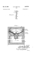
- Figure 1 is an enlarged vertical sectional view of a simplified fuse having a temperature-responsive delay mechanism embodying features of the invention in combination with an explosive or burster;
- Figure 2 is an exaggerated enlarged view of -a form of firing pin used in the mechanism shown in Fig. 1;
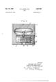
- Figure 3 is an enlarged vertical sectional view of a temperature-responsive delay fuse engaged in an incendiary bomb;
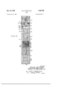
- Figure 4 is a vertical sectional view of an ex plosive incendiary bomb in broken sections with a temperature-responsive delay fuse such as depicted in Figure 3.
- a simplified delay fuse combined with a high explosive burster as diagrammatically illustrated in Figure 1 is adapted particularly for use with various heat generating munitions, as for example, pocket incendiaries or small re starters implaced for sabotage, smoke pots, and the like ⁇
- It i is a device which may be attached to such munitions or be implaced separately, e. g., Where it is desired to deter fireghting, salvaging, or interference with the operation of the munitions.
- the device shown in Figure 1 comprises a casing I divided into principal compartments by partition 2, an upper compartment 3 for housing a firing mechanism activated by predetermined temperature changes and a lower compartment 4 inclosing a high explosive charge of the bursting type, e. g. tetryl, trinitrotoluene, -or the like.
- a hollow plug 5 having a threaded engagement with partition 2 holds a primer or primer-detonator element cap 6 of suitable composition for ring the high explosive charge in compartment 4 upon receiving-a point impact from a striker or firing pin firing mechanism in compartment 3.
- the casing I may be made of metal or plastic.
- the firing mechanism housed in compartment 3 simply consists in a bimetallic disc 'I constructed to abruptly change its curvature upon predetermined changes in temperature and with these changes to bring a firing pin 8 into a firing action.
- the bimetallic disc has a small hole 9 through the center.
- the hole S is slightly small- I er than the cross section at the shoulder I0 below the notch II on the firing pin 8 so that it is relatively easy for the firing pin to be pushed down through the hole until the firing pin 8 is locked in the hole 9 at notch I I.
- the mechanism is designed to operate in the following manner:
- the bimetalllicd-ise 'If ata predetermined temperature level snaps'back intothe original position due to the relatively great contraction of themetalin the' upper lamina; andin f thus coming back to its: original position :with vthe :firing pin extended downwardly, the pointnISoiv theiring'- pin strikes ther primer orprimeredetio- ⁇ nating'materia-l in cup G-and thereupon;cletonates.
- ing-pin ⁇ 8 preferably" has ataperedf sidesV between the ⁇ ⁇ u-ppernotch i Iy fandfthelower notch i2.' 'to en'- able the pin ⁇ to; slidefmorefeasily into thearmed -f position-.e
- Thebimetallicfsnapldisci 'I may: comprise-a sheet-of ⁇ metalhaving aY relatively highxcoeileient expansionA such asfbrass, Moneli'metal'forsteel' laminated to ashe'et of metal having a relatively' lourcoecient .of expansionfsuch as iron, nickelv iron, ⁇ orfnvar bywelding, brazingysoldering; or riveting: Satisfactory bimetallie ⁇ discs. used in demonstrating. :the: invention are commercially available 'products soldiv under f the .tradername :of .v Klixon. .Howeven it. is-to-Ivbef-understoocd. thatA other typesaof ⁇ mechanisms: :which fare: similarly: Y responsive tochanges in'temperature by abrupt ⁇ shifts-in position. mayfalsov be used; i
- Thermitfbombioffa type illustrated intig-wY ure 't comprises a, cast body 12 5V formed irommagsv nesium a11oy,falu1ninium, steel Vor .iotherisnitable f.- metals,. and ⁇ contains; a Thermiti-typecharge: 25 It representsa'a; standardized type of bomblra'vingan overall'. ⁇ length of.
- Yabout 2'1 inches ⁇ T Kunststoffcdy' V25 may be cylindrical or hexagonal-a1,.It/ isgpro-e vided .With'tail fins 21 Yof sheetzsteel and :with :"a heavy steel, or cast-ironnose plugin for insuringg.;4V true: Hight,- and penetrationzo the ;target.:
- the lower depression at 29l marks the' bound-Wl arybetween Athe Thermit charge .2.6 anda, pressed. bed of insulated material, 'suchjasc-asbestos
- is held in a holder 32 of steel or taluminium, tted against the shoulder 33 formed inthe body 25.
- contains a primer or detonator material, such as lead azide or fulminate, which' is adapted to be set oi or-red when struck by the firing pin 34 projecting from a weight porltionior striker 35 downwardly in alignment with thewerucei axis of the cap 3
- the striker 35 is slidablymounted in a cylindrical holder 3S which is flanged inwardly ⁇ at vthe upper end to form a hole y3'
- the striker 35 is normally retained in the suspended position shown by means of an ailixed'screw or pin 38 which is supported by a cross-shaped brass member 39 resting above the holder4 36.
- the cross-shaped member 39 is made of 'brassror .similar deformable material, so that uponpredeterminated impact of the bomb, the arms ofzthe cross-shaped member fold up and permitjthe striker 35 to move downwardly towardthecap3l.
- normally held outwardly bears against a spring within the housing 42 and has an inner projection which extends under the firing pin 35 to block the movement of the firing pin35 when the pin 4
- the bomb is adapted to be loaded in clusters of, for example, 50 or more bombs, .whichtted together hold the safety pins in an unarmed position.
- Thecluster is adapted to be dropped eiectively from bombing aircraft.'
- when struck a sharp blow by the point flashes back into the depression 30 of the rst fire charge 30 which thereupon becomes ignited.
- the plugs placed in the vent holes 44 may be made of rubber, fiber, cork or other yieldable materials, or be pressed in metal cups.
- the outside surfaces of the plugs may be coated with a waterproof cement or lacquer, or the plugged holes 44 may be covered with Waterproof tape.
- the rst re charge mixture 30 is capable of being readily. ignited, and burns at a temperature sufliciently high ⁇ to ignite the adjacent Thermit charge 26.
- the temperature-responsive fuse assembly is attached to the bomb nose plug 28 and operates in the same manner as the assembly described with reference to Figure 3.
- a ring pin 8 attached to a bimetallic snap disc 1 normally is disposed to prevent movement of the slider i6 so that the primer cup 6 within the slider IB is held in an unarmed positionuntil the disc snaps upwardly due to heat conducted through the body 25 from the burning Thermit charge.
- the upward movement of the ringV pin 8 with the disc releases theslider I6 so that the compressed spring I8 moves the slider into a position where the primer cup 6 is in alignment with the firing pin 8.
- the bimetallic disc snaps down- Wardly and forces the firing pin to 4strike the.
- a charge of high explosives e. g., tetryl or T. N. T.
- tetryl e.g., tetryl or T. N. T.
- the tube 45 having a thin copper wall may contain lead azide; with T. N. T. as the high explosive, the tube 45 may contain an upper layer of lead azide and a lower layer of tetryl asa booster.
- a nose plug 28 The bottom of a nose plug 28 is closed by a threaded steel plug 46.
- An asbestos pad .47 is placed between the high explosive charge and the plug 46 and another pad 48 of .asbestos or similar inert brous insulating material is placed at the top of the high explosive charge in compartment 4 so that it surrounds the tube 45.
- the detonator or booster in the tube 45 is detonated, and in turn the high explosive within the compartment 4 undergoes explosive action which shatters'nose plug 28 and produces rapid flying metal fragments.
- the primer used with the temperature-responsive fuse assembly be sumciently insensitive to high temperatures developed in the burning of the bomb incendiary charge and also insensitive to the shock created by impact of the bomb when the bomb strikes the target at high velocities.
- insulation such as the insulation 49, and other insulation which may be added, but it has been found desirable to use a special type of primer developed for the purpose in hand.
- a special primer found to function satisfactorily in conjunction with the temperature-responsive fuse mechanism in an explosive incendiary bomb is prepared by mixing antimony sulde and potassium chlorate into a thick paste with a solution of cellulose acetate. This mixture is placed in the primer cup 6. In using the described mixture, the point I 3 of the firing pin 8 is coated with a mixture of red phosphorus and a heat-resistant abrasive such as Alundum (aluminium oxide), with a high temperature-resistant binder.
- a 'temperature-responsive 'delayed action ⁇ fusel comprising a bimetallic snap ⁇ disc-rafiring ⁇ pin 'atei tachedf--t'of'said'disc; aslida-ble" primer holder 'disl-l posed "assembly with said riiringpin 'to kbe hel'd' normalityl in an na-rrrieei'positioirbuttoA bemoved" lmetaliicfdisc which.
- slider contain@ alignmentV with said riI-ignpinsanda: compressed il spring exerting a force-fonvtheiislider--tomoveit into -a position wherev the prmiar'fcumis in'ali'gmment with the iring pin
Landscapes
- Engineering & Computer Science (AREA)
- General Engineering & Computer Science (AREA)
- Chemical & Material Sciences (AREA)
- Combustion & Propulsion (AREA)
- Portable Nailing Machines And Staplers (AREA)
Description
Nov. 15, 1949 w. w. CARR ETAL 2,487,789
FUSE Filed June 20, 1944 3 Sheets-Sheet 1 4 ME. f77/ed /LES/ mf. 04e@ L u/s G. MAL/ 5 .5 /v M. DQ/NOE, c/Q.
Mams
Nov. l5, 1949 Filed June 20, 1944 w. w. CARR ETAL 2,487,789
FUSE
3 Sheets-Sheet 2 Nov. '15, 1949 w. w. CARR Erm. 2,487,789
i FusE Filed June 2o, 1944 s Sheets-sheet s w; M W www,
Patented Nov. 15, 1949 'rN'r OFFICE FUSE Wiley W. Carr and Louis G. Willke, United States Army, and Leon M. Prince, Jr., New York, N. Y.
Application J une 20, 1944, Serial No. 541,256
(Granted under the act of March 3, 1883, as amended April 30, 1928; 370 0. G. 757) 4 Claims.
The invention described herein may be manufactured and used by or for the Government, for governmental purposes, Without payment to us of any royalty thereon.
This invention relates to a fuse mechanism particularly useful for effecting a detonation of an explosive charge in an incendiary munition, such as explosive incendiary bombs.
Explosive incendiary bombs were developed to discourage attempts to extinguish the burning combs. Such bombs have been designed to be similar in appearance and action to non-explosive incendiary bombs with which they are used aut to differ in containing an explosive charge which becomes fired at such a time after burning as `to make approach to the bombs hazardous. Ihe explosive incendiary bombs are intended to ce deceptive and to run interference, so-to-speak, against reghting action. However, hitherto developed explosive incendiaries have had the tendency to explode very shortly after their burning action is started, thus depriving the bombs of effective incendiary action, revealing the presence of the bombs, and permitting ireghters to begin extinguishing the bombs at an incipient stage of their action.
The present invention is concerned with providing explosive incendiaries which have a delayed action, which are particularly hazardous when efforts are made to extinguish them, which produce concentrated incendiary effects for a substantial period until they become extinmaining unarmed when subjected to heat at high temperatures and becoming armed when cooled ay involving the use of a suitable thermostatic device, such as a bimetallic disc which undergoes diiferential expansion with predetermined temperature changes, in association with other l firing means.
Further objects will become apparent from the following description taken in conjunction with the drawings, wherein:
Figure 1 is an enlarged vertical sectional view of a simplified fuse having a temperature-responsive delay mechanism embodying features of the invention in combination with an explosive or burster;
Figure 2 is an exaggerated enlarged view of -a form of firing pin used in the mechanism shown in Fig. 1;
Figure 3 is an enlarged vertical sectional view of a temperature-responsive delay fuse partielllarly adapted for use in an incendiary bomb;
Figure 4 is a vertical sectional view of an ex plosive incendiary bomb in broken sections with a temperature-responsive delay fuse such as depicted in Figure 3.
A simplified delay fuse combined with a high explosive burster as diagrammatically illustrated in Figure 1 is adapted particularly for use with various heat generating munitions, as for example, pocket incendiaries or small re starters implaced for sabotage, smoke pots, and the like` It i is a device which may be attached to such munitions or be implaced separately, e. g., Where it is desired to deter fireghting, salvaging, or interference with the operation of the munitions.
The device shown in Figure 1 comprises a casing I divided into principal compartments by partition 2, an upper compartment 3 for housing a firing mechanism activated by predetermined temperature changes and a lower compartment 4 inclosing a high explosive charge of the bursting type, e. g. tetryl, trinitrotoluene, -or the like. A hollow plug 5 having a threaded engagement with partition 2 holds a primer or primer-detonator element cap 6 of suitable composition for ring the high explosive charge in compartment 4 upon receiving-a point impact from a striker or firing pin firing mechanism in compartment 3. The casing I may be made of metal or plastic.
The firing mechanism housed in compartment 3 simply consists in a bimetallic disc 'I constructed to abruptly change its curvature upon predetermined changes in temperature and with these changes to bring a firing pin 8 into a firing action. The bimetallic disc has a small hole 9 through the center. The hole S is slightly small- I er than the cross section at the shoulder I0 below the notch II on the firing pin 8 so that it is relatively easy for the firing pin to be pushed down through the hole until the firing pin 8 is locked in the hole 9 at notch I I.
The mechanism is designed to operate in the following manner:
While the upper compartment 3 is relatively cool, the disc 'I clamped at its periphery in the casing I is in a downward position with the ring pin Bretained in the center hole 9 at the lower The upward arching of the disc I drives the head l;
I4 of the ring pin 8 against the top of the compartment 3, pushing the ring pin through the hole 9 until the notch I I is engaged1 by the V'disc-rte"v lock the firing pin in place. an armed position and remainsthus. vuntil cornpartment 3 becomes cooled to a predetermined temperature level. Upon cooling either natural-f,
ly or articially with water or other cooling The. fuse-fis now, ini.
type extinguishers, the bimetalllicd-ise 'If ata predetermined temperature level snaps'back intothe original position due to the relatively great contraction of themetalin the' upper lamina; andin f thus coming back to its: original position :with vthe :firing pin extended downwardly, the pointnISoiv theiring'- pin strikes ther primer orprimeredetio-` nating'materia-l in cup G-and thereupon;cletonates.,
the exposive charge in compartment 4. The rire.
ing-pin `8 preferably" has ataperedf sidesV between the` `u-ppernotch i Iy fandfthelower notch i2.' 'to en'- able the pin` to; slidefmorefeasily into thearmed -f position-.e
The' heat required to :operate the mechanisme,
maybe"derivedfdirectlyfromv a munition in which.
the device is installed or, in specialapplicationa'r an-l'auxiliary' source'v of heatimay bez supplied.A The simplified f devicev which "may-f, bei manufactured,
3.5 that the-action of the Vpu'iniermaybe transmitted at `low -'cost-fand. rwhich may: be. conveniently handled and carried: is Very useful .iniconnection Witlrfirestarters. as 'Yinconspi'cuously srnallarticiesl to l be: placed in strategic positionsswhere a'. confiagration Yis torbe started so that f-,t'ney :will 'explodey 'whenY attempts subsidessuiciently; if still: unexploded,A they will f tend-to 'scatter Ithe re and causeiurther disor-s der andfspreading of the' conlagration;
Thebimetallicfsnapldisci 'I may: comprise-a sheet-of `metalhaving aY relatively highxcoeileient expansionA such asfbrass, Moneli'metal'forsteel' laminated to ashe'et of metal having a relatively' lourcoecient .of expansionfsuch as iron, nickelv iron, `orfnvar bywelding, brazingysoldering; or riveting: Satisfactory bimetallie` discs. used in demonstrating. :the: invention are commercially available 'products soldiv under f the .tradername :of .v Klixon. .Howeven it. is-to-Ivbef-understoocd. thatA other typesaof` mechanisms: :which fare: similarly: Y responsive tochanges in'temperature by abrupt` shifts-in position. mayfalsov be used; i
thefuse and explosive combinationsare v to be=employed in situations :Where ,veryihigh tem; v
commerciali primer'lcaps I'n certain l instances,
particularly in adaptationsfof the device forA use in-conjunctionV` with linc'endiaryrbombsj special primersl are-preferred ,orrequ'i-red as willbe'here-z' inafter explained.
a fuse, mechanism, whichcorresponds in a nume. benof .features to the; us'c. mechanism shown in Figurer It hasta bimetanic, disci clamped at. Q
its, ,periphery fbetween vthe threaded plug. vI5.,and.
Referring to Figure 3, the-device illustratedh'as. 70
casingV I, but the disc 1 is permanently locked to firing pin 8 by having the groove II of the ring pin securely held Within a center hole 9. A cavity in the base of the plug I5 and the upper hollow part of the casing I form a compartment 3 which provides space for the flexing movement of the disc f The primer 6 is contained-"in a cylindrical slider Ilifsdisposed to slide or be reciprocated Within a 10..
cylindrical bore II inside the casing I when the point I3 of the ring pin 8 is not in a position to obstruct 'movement offthe slider. The slider I6 isheldimthezunarmed.position by the firing pin 8, the point I3 of which ts into a hole Il in the upperpart oftheslider. The ring pin 8 is withdrawn-from the hole when the curvature of the disc 'I is reversed by heat at a predetermined temperatureilevel-and the'slider I6 is moved by coiled spring -I'LB- underl compression toward the left so that when the disc snapsffto the original shape, exing downwardly'. on cooling, the. 4firing'spin:'8. strikes. downwardly in alignments with"thefpmirneri f caprG andthe Vfiring point Ispierces thetprimei i, The spring I8 is compressed between-*.theisliderrI'Ii andtheba'ckfside of "af threadedrplugiiwhicn actsl asa closure for the. fcyliridricalaibore.:l'lini casingy Ir. A cylindrical. depressionsZI-,ifatzthafend of the slider I6 servesrtoiholdithe spring/I8 una horizontalv position. A grooveZZcinJthe slicieriIf-G..l
fserves asta, guide forma short:Xedxpinrlfiproe A jecting sfrorn Vthe wall: of 'thexboreflt'ty and?i'llvierebylr` prevents rotation ofthe slider.; 5A hole: 2Min the; bottom of casing l acts las a passageifonawflas al produced whenxtheprimers'acticn is initiatects to a' detonator or booster: The assembly: that, has been explained will befurther describedwith'ref-g erencefi'to :Figurei in ,Which'iiti is'- illnstratedsas or installed 4in a Thermit-typezf incendiary. bomb; The Thermitfbombioffa type illustrated intig-wY ure 't comprises a, cast body 12 5V formed irommagsv nesium a11oy,falu1ninium, steel Vor .iotherisnitable f.- metals,. and` contains; a Thermiti-typecharge: 25 It representsa'a; standardized type of bomblra'vingan overall'.` length of. Yabout 2'1 inches `Tliebcdy' V25 may be cylindrical or hexagonal-a1,.It/ isgpro-e vided .With'tail fins 21 Yof sheetzsteel and :with :"a heavy steel, or cast-ironnose plugin for insuringg.;4V true: Hight,- and penetrationzo the ;target.:
The nThermit charge. 2liv which` forms thefinaini. part of thecore Within body 2,5 lias'a. compositiorrlir represented;byxthe following in 'percentage'..iby weightz Perfcentn, Aluminium, granular ljitod n Iron oxide: scale,ior;iron ore; r3-.5to 4.445 Aluminium; grained.: .8'.8 to: Y9.23ct Barium initrate ".z Zrito'ZBAf Sulfur.: La to. 2,1';
The4 weight; of the fTliermitLtypeicharge A*2 3 fin 'a bomb having a total 'Weight vof approximately Li lbs. with a body- Weighingaboutlf lbll oz.1iis ofv the rorder of 8` tofIOoz.;:The""IThermit chargezj' is loaded' into "the: 'body' 25" in 'three Uor' four'jap- Y proximately "equal increments under :a dead'l'oad'f.' pressure'of about 6.000"to 7000'1bsi usinga ram shaped to form a truncated'conical:depressioniV corresponding to the' shapev of the' depression shown i'nFigurer at 29 and 29"?"V The lower depression at 29l marks the' bound-Wl arybetween Athe Thermit charge .2.6 anda, pressed. bed of insulated material, 'suchjasc-asbestosor magnesium. oxidey `which on thebottom 1 side. Lis,- pressedL againstthe top. of. .plug..t5, whicniorms y.
-imagnesiumpowder `and 75% barium chromate,
about 19 te 21 grams of these ingredients, inti- .j mately mixed and pressed by a ram under a dead load of about 6000 to 7000 lbs., the ram being vi shaped to form a rounded depression 30'.
i The primer cap 3| is held in a holder 32 of steel or taluminium, tted against the shoulder 33 formed inthe body 25.
f, The cap 3| contains a primer or detonator material, such as lead azide or fulminate, which' is adapted to be set oi or-red when struck by the firing pin 34 projecting from a weight porltionior striker 35 downwardly in alignment with thewerucei axis of the cap 3|. The striker 35 is slidablymounted in a cylindrical holder 3S which is flanged inwardly `at vthe upper end to form a hole y3'|. The striker 35 is normally retained in the suspended position shown by means of an ailixed'screw or pin 38 which is supported by a cross-shaped brass member 39 resting above the holder4 36.- The cross-shaped member 39 is made of 'brassror .similar deformable material, so that uponpredeterminated impact of the bomb, the arms ofzthe cross-shaped member fold up and permitjthe striker 35 to move downwardly towardthecap3l.
The ring pin assembly is held in place by screws 4D.. A safety pin`4| normally held outwardly bears against a spring within the housing 42 and has an inner projection which extends under the firing pin 35 to block the movement of the firing pin35 when the pin 4| is depressed. With this type of safety pin, the bomb is adapted to be loaded in clusters of, for example, 50 or more bombs, .whichtted together hold the safety pins in an unarmed position. Thecluster is adapted to be dropped eiectively from bombing aircraft.'
In a bombing operation, when a cluster of the bombs is dropped toward a target, shortly after release from the bomb bay of the aircraft,
bands holding the bombstogether in a cluster are broken, and the clustered bombs thereafter separate fro'meach other. As the bombs separate, the safety pins are forced outwardly by compressed springs within Vthe housings 42 so that their linner projectionsdo not obstruct the movement of the safety pin 35. Upon impact of the nose of a bomb, the inertia of the striker 35 forces it to move abruptly and at the same time to deform the retaining cross-shaped member 39 so that the ring pin 34 pierces the primer in cap3l.
The primer cap 3| when struck a sharp blow by the point flashes back into the depression 30 of the rst lire charge 30 which thereupon becomes ignited.
Gaseous products of combustion from the ignition of the rst fire charge 30 create sufficient pressure to blow out plugs in the vent holes 44 and thus prevent explosion of the bombs. The plugs placed in the vent holes 44 may be made of rubber, fiber, cork or other yieldable materials, or be pressed in metal cups. In order to make the bomb waterproof, the outside surfaces of the plugs may be coated with a waterproof cement or lacquer, or the plugged holes 44 may be covered with Waterproof tape.
The rst re charge mixture 30 is capable of being readily. ignited, and burns at a temperature sufliciently high` to ignite the adjacent Thermit charge 26.
As previously indicated, the temperature-responsive fuse assembly is attached to the bomb nose plug 28 and operates in the same manner as the assembly described with reference to Figure 3. A ring pin 8 attached to a bimetallic snap disc 1 normally is disposed to prevent movement of the slider i6 so that the primer cup 6 within the slider IB is held in an unarmed positionuntil the disc snaps upwardly due to heat conducted through the body 25 from the burning Thermit charge. The upward movement of the ringV pin 8 with the disc releases theslider I6 so that the compressed spring I8 moves the slider into a position where the primer cup 6 is in alignment with the firing pin 8. After this movement of the slider, when the bomb is cooled naturally or artificially to a predetermined temperature level, the bimetallic disc snaps down- Wardly and forces the firing pin to 4strike the.
primer in cup 6.
Within the lower hollow portion or compartment 4 of thenose plug 28 is placed a charge of high explosives, e. g., tetryl or T. N. T. Near the top of compartment 4 and in alignment with the hole 24, which is directly in line with the primer when it is in the armed position, is placed a booster or detonator tube 45, whichever is needed. For example, with tetryl as the high explosive surrounding the tube 45, the tube 45 having a thin copper wall may contain lead azide; with T. N. T. as the high explosive, the tube 45 may contain an upper layer of lead azide and a lower layer of tetryl asa booster.
The bottom of a nose plug 28 is closed by a threaded steel plug 46. An asbestos pad .47 is placed between the high explosive charge and the plug 46 and another pad 48 of .asbestos or similar inert brous insulating material is placed at the top of the high explosive charge in compartment 4 so that it surrounds the tube 45.
When the primer in cup 6 ashes through hole 24, the detonator or booster in the tube 45 is detonated, and in turn the high explosive within the compartment 4 undergoes explosive action which shatters'nose plug 28 and produces rapid flying metal fragments.
It is important that the primer used with the temperature-responsive fuse assembly be sumciently insensitive to high temperatures developed in the burning of the bomb incendiary charge and also insensitive to the shock created by impact of the bomb when the bomb strikes the target at high velocities. To some extent the flow of heat from the burning incendiary charge can be retarded by insulation, such as the insulation 49, and other insulation which may be added, but it has been found desirable to use a special type of primer developed for the purpose in hand.
A special primer found to function satisfactorily in conjunction with the temperature-responsive fuse mechanism in an explosive incendiary bomb is prepared by mixing antimony sulde and potassium chlorate into a thick paste with a solution of cellulose acetate. This mixture is placed in the primer cup 6. In using the described mixture, the point I 3 of the firing pin 8 is coated with a mixture of red phosphorus and a heat-resistant abrasive such as Alundum (aluminium oxide), with a high temperature-resistant binder. The
'7 binder- 'maybe;amalkydatypeiresin:orthermosetw ting resin, Which is synthesizedzorrpolymeiiize'd' `1n :n thrxrrixtunezw-itha solvent: suci'mas ethyi'alcoho'l for thimaing anda; basessuohfas fsodiunrfhydiroxidef sol-uti'ontor1cause poIy-m'erizati'oni Thecoaftedl-r.- ing pins and the mixture in the oapsfflzarey baked for"fsuiiitii'entii'timeA atzia `suitaivle temperature to` harden-whef'described'compositions;e. fgifofsixi-i howsiat-about 10U-"to 21251956; yPTI-ieV resulting-fiiash mixture iny ther-capI I 6" corresponcfsfto-fth. coni-posi;- 1 f tion:'onfetlfle head Joffra vsafet'y!match#While theoha1-d`eneci==fc'oating'V on the firing pin 'L8 corresponds*4 f1 to :thscratchermixture l`whichI 'is usedifwithf a f safety'matchv" Each of these compositions-'separateify is suitablyfinsensitivef-to heat at higfllii tem#- peraturesf E I i'sftobe notecthat'the top 1`eve1'oi:`l theiiashf* composition inithe prim-er cup-'A6- s'ho'ufliiloe'suchI thaf'tivthef"Verticali-dimensionthi'ougn whichl the tiring pin` i is 'caused' -t'o f travel I'i'n firing' action-i is' '2o within suitable small tolerances. In generalffthe traveifdistanceof the iiin'g pinamounts to about 6% oftheifdia'meterof thevbimetaliic disc, unless-M the `niovement'of ther discy i's inadeto impart-moe tiorihdii'ectly'to-ithe firing pin through 'a system of levers arranged to magnify the moVem-entfof" the-disco In" other" Words the; temperaturezere; sponsiveiel'ement vmayaci-rasa triggerfor aictuai2 ineiihe'movementof theri'ng. means.
Tests conductedon a number of Amunitions indicat'ethat a high percentagefof functioning can be" obtairreciA witir thef descriloe'dtemperature-respon sive-fuse' and consistent good' results were obtained with I 'explosive incendiary' bombs having the in# stailedfuse. The bombs lWeretestedvv and found to `bei practical. Y i
Iii-"is understood{inattivi-e'A fuse mechanism d`e scribetiissubjecttc Various' modifications; includ-1 ing substitutions of equivalentv temperature'ref` sponsivel elements;y primers;A detonante,4 'and A.ex-"- fw' plosives, also; in'assembly construction: Also'it' is :evident *thatV the' '-temperature-responsive fuse mechanism; has -vwide I-applicationi in i commotion withvarioustypes ofbombs andothe'r munitions: Although@ the invention 'has' beenY` described reference to exemplaryembodiments;l different" embodimentsmay' be 'madef-wit'rout4 departing... from the-"scopethereof.v
1'. In combination Witii-A anexpIosive munition, a 'temperature-responsive 'delayed action `fusel comprising a bimetallic snap` disc-rafiring` pin 'atei tachedf--t'of'said'disc; aslida-ble" primer holder 'disl-l posed "assembly with said riiringpin 'to kbe hel'd' normalityl in an na-rrrieei'positioirbuttoA bemoved" lmetaliicfdisc which. changes itsciiuzvatur'e1 abriiptly v locked' from .its 'unarmedrpositiom'a therein-,1; a.: high ,explosive ohargev infhelfw other es:
compartment, a primer disposewithmthe ing; .vtodetonate the high expiosivenchai'gei: andc' firing pin connected withsair dis'cto :betactuaait into-icontactvwith theiiprimer when? thendism'is :s
cooled from-a high-:temperature:
4. Incombi-nationWithfaniexplosivedncendariit bomb` i containing a Thermit mititurezchatgefmndaii a high explosive bursteigf-v a -temperatureenespm1snsive-fdelayed..` action 'f useif-c.on1prisingsy a at i predetermined high.; anet..:l'owf\ temperature-sse: levels.; a ring: pin attachedto'said idiscrsa'rc1piani-isi.' actuated into; ifeciprocatory"mommentzibynsairk disc-in itschanging `of curvatura-fa. slider contain@ alignmentV with said riI-ignpinsanda: compressed il spring exerting a force-fonvtheiislider--tomoveit into -a position wherev=the prmiar'fcumis in'ali'gmment with the iring pin When the. slider.'- issunii...
REEERENGESm GITEDL 1.
UNTI'ED"STAIES'"PATEN1S L Namen.; Dai-geit@ 708,411 Semple Sept. 2, tgzl 1,'4-35y228r'f` Hammond'- Ncvf 19%.. 1,48137198 Hammond. Jan 29f9222 f= 226635371.` Ennemi; newasgaffrom FOREIGN PATENTWI..
Number/g @ounztivy'y 1 Date-#b 13-'7-,852 Great-i Britain-' Jan. '15;"11920i525i 450.53637 Great-:Britain Maw:115,`f1939i 325,98? Italy .Eem-i4, iifli
Priority Applications (1)
| Application Number | Priority Date | Filing Date | Title |
|---|---|---|---|
| US541256A US2487789A (en) | 1944-06-20 | 1944-06-20 | Fuse |
Applications Claiming Priority (1)
| Application Number | Priority Date | Filing Date | Title |
|---|---|---|---|
| US541256A US2487789A (en) | 1944-06-20 | 1944-06-20 | Fuse |
Publications (1)
| Publication Number | Publication Date |
|---|---|
| US2487789A true US2487789A (en) | 1949-11-15 |
Family
ID=24158827
Family Applications (1)
| Application Number | Title | Priority Date | Filing Date |
|---|---|---|---|
| US541256A Expired - Lifetime US2487789A (en) | 1944-06-20 | 1944-06-20 | Fuse |
Country Status (1)
| Country | Link |
|---|---|
| US (1) | US2487789A (en) |
Cited By (14)
| Publication number | Priority date | Publication date | Assignee | Title |
|---|---|---|---|---|
| US2516234A (en) * | 1941-09-27 | 1950-07-25 | Midgley Albert Henry | Fuse for bombs and other missiles or projectiles |
| US2850978A (en) * | 1955-03-02 | 1958-09-09 | Philip J Franklin | Safety device for ordnance fuzes |
| US3020845A (en) * | 1960-11-04 | 1962-02-13 | Jules M Hardesty | Temperature responsive firing mechanism |
| US3119303A (en) * | 1960-09-23 | 1964-01-28 | Hotchkiss Brandt | Gyratory self-propelled projectile |
| US3702589A (en) * | 1968-02-08 | 1972-11-14 | Atomic Energy Commission | Bimetallic temperature sensing device |
| US3854401A (en) * | 1967-12-01 | 1974-12-17 | Us Army | Thermal ignition device |
| US3858516A (en) * | 1951-04-20 | 1975-01-07 | Us Army | Thermal arming system |
| US3971319A (en) * | 1974-10-18 | 1976-07-27 | Hercules Incorporated | Thermally actuated percussion initiatable explosive cartridge assembly |
| US4029016A (en) * | 1976-06-29 | 1977-06-14 | The United States Of America As Represented By The Secretary Of The Army | Plural mode fuze |
| US4047484A (en) * | 1976-06-29 | 1977-09-13 | The United States Of America As Represented By The Secretary Of The Army | Fuze with bimetallic spring delay module |
| FR2456935A1 (en) * | 1979-05-15 | 1980-12-12 | Bofors Ab | DEVICE FOR SECURING AND PRIMING THE DETONATOR ROCKET OF AN ARTILLERY PROJECTILE |
| US4604953A (en) * | 1984-04-26 | 1986-08-12 | Hi-Shear Corporation | Void-sensing fuze |
| WO1990001635A1 (en) * | 1988-08-08 | 1990-02-22 | Hughes Aircraft Company | A thermally initiated mechanically fired device for providing protection against slow cook-off |
| US6629499B1 (en) * | 2002-03-12 | 2003-10-07 | The United States Of America As Represented By The Secretary Of The Navy | Temperature activated mechanical timer |
Citations (6)
| Publication number | Priority date | Publication date | Assignee | Title |
|---|---|---|---|---|
| US708411A (en) * | 1902-05-09 | 1902-09-02 | John B Semple | Projectile. |
| GB137852A (en) * | 1918-09-10 | 1921-03-10 | Mario Saini | Improvements in and relating to cartridges |
| US1435228A (en) * | 1914-12-21 | 1922-11-14 | Jr John Hays Hammond | Incendiary shell |
| US1481798A (en) * | 1917-06-27 | 1924-01-29 | Said Hammond | Projectile |
| GB505637A (en) * | 1937-11-15 | 1939-05-15 | Samuel Francis Roberts | Incendiary bombs for instructional and demonstration purposes |
| US2266537A (en) * | 1937-02-16 | 1941-12-16 | William B Elmer | Snap acting device |
-
1944
- 1944-06-20 US US541256A patent/US2487789A/en not_active Expired - Lifetime
Patent Citations (6)
| Publication number | Priority date | Publication date | Assignee | Title |
|---|---|---|---|---|
| US708411A (en) * | 1902-05-09 | 1902-09-02 | John B Semple | Projectile. |
| US1435228A (en) * | 1914-12-21 | 1922-11-14 | Jr John Hays Hammond | Incendiary shell |
| US1481798A (en) * | 1917-06-27 | 1924-01-29 | Said Hammond | Projectile |
| GB137852A (en) * | 1918-09-10 | 1921-03-10 | Mario Saini | Improvements in and relating to cartridges |
| US2266537A (en) * | 1937-02-16 | 1941-12-16 | William B Elmer | Snap acting device |
| GB505637A (en) * | 1937-11-15 | 1939-05-15 | Samuel Francis Roberts | Incendiary bombs for instructional and demonstration purposes |
Cited By (16)
| Publication number | Priority date | Publication date | Assignee | Title |
|---|---|---|---|---|
| US2516234A (en) * | 1941-09-27 | 1950-07-25 | Midgley Albert Henry | Fuse for bombs and other missiles or projectiles |
| US3858516A (en) * | 1951-04-20 | 1975-01-07 | Us Army | Thermal arming system |
| US2850978A (en) * | 1955-03-02 | 1958-09-09 | Philip J Franklin | Safety device for ordnance fuzes |
| US3119303A (en) * | 1960-09-23 | 1964-01-28 | Hotchkiss Brandt | Gyratory self-propelled projectile |
| US3020845A (en) * | 1960-11-04 | 1962-02-13 | Jules M Hardesty | Temperature responsive firing mechanism |
| US3854401A (en) * | 1967-12-01 | 1974-12-17 | Us Army | Thermal ignition device |
| US3702589A (en) * | 1968-02-08 | 1972-11-14 | Atomic Energy Commission | Bimetallic temperature sensing device |
| US3971319A (en) * | 1974-10-18 | 1976-07-27 | Hercules Incorporated | Thermally actuated percussion initiatable explosive cartridge assembly |
| US4029016A (en) * | 1976-06-29 | 1977-06-14 | The United States Of America As Represented By The Secretary Of The Army | Plural mode fuze |
| US4047484A (en) * | 1976-06-29 | 1977-09-13 | The United States Of America As Represented By The Secretary Of The Army | Fuze with bimetallic spring delay module |
| FR2456935A1 (en) * | 1979-05-15 | 1980-12-12 | Bofors Ab | DEVICE FOR SECURING AND PRIMING THE DETONATOR ROCKET OF AN ARTILLERY PROJECTILE |
| US4328752A (en) * | 1979-05-15 | 1982-05-11 | Aktiebolaget Bofors | Safety and arming device for a projectile fuze |
| US4604953A (en) * | 1984-04-26 | 1986-08-12 | Hi-Shear Corporation | Void-sensing fuze |
| WO1990001635A1 (en) * | 1988-08-08 | 1990-02-22 | Hughes Aircraft Company | A thermally initiated mechanically fired device for providing protection against slow cook-off |
| US4961313A (en) * | 1988-08-08 | 1990-10-09 | Hughes Aircraft Company | Thermally initiated mechanically fired device for providing protection against slow cook-off |
| US6629499B1 (en) * | 2002-03-12 | 2003-10-07 | The United States Of America As Represented By The Secretary Of The Navy | Temperature activated mechanical timer |
Similar Documents
| Publication | Publication Date | Title |
|---|---|---|
| US2487789A (en) | Fuse | |
| US3313236A (en) | Multiple function fuzes | |
| US3055300A (en) | Rocket flare head | |
| US3137231A (en) | Chaff dispenser system | |
| US6253680B1 (en) | Diversionary device | |
| US3645208A (en) | Fuzeless target practice cartridge | |
| US1316607A (en) | Detonator for projectiles | |
| US1311104A (en) | Detonator por ordnance-projectiles | |
| US3635162A (en) | Practice bomb | |
| US4770096A (en) | Safing and arming mechanism | |
| US3291049A (en) | Impact spotter bullet | |
| US2678603A (en) | Delayed action explosive munition | |
| US3392672A (en) | Flare lighter | |
| US2455603A (en) | Fuse | |
| US1545139A (en) | Fuse | |
| US2960934A (en) | Hand illuminating grenade | |
| US3097600A (en) | Sound generator | |
| US2805623A (en) | Tail fuze for an ordnance missile | |
| US2725011A (en) | Base self-destruction fuze for ordnance projectiles | |
| US1216364A (en) | Cumulative artillery-projectile. | |
| US2812714A (en) | Firing device for a point detonating fuze | |
| US2084218A (en) | Delay action fuse for projectiles and the like | |
| US1988446A (en) | Flare | |
| US3425352A (en) | Projectile fuze capable of self-destruction | |
| CN115325890A (en) | A flameproof high-safety ignition fuze |