US2487724A - Artificial arm - Google Patents
Artificial arm Download PDFInfo
- Publication number
- US2487724A US2487724A US788433A US78843347A US2487724A US 2487724 A US2487724 A US 2487724A US 788433 A US788433 A US 788433A US 78843347 A US78843347 A US 78843347A US 2487724 A US2487724 A US 2487724A
- Authority
- US
- United States
- Prior art keywords
- housing
- jaws
- secured
- rack
- pivoted
- Prior art date
- Legal status (The legal status is an assumption and is not a legal conclusion. Google has not performed a legal analysis and makes no representation as to the accuracy of the status listed.)
- Expired - Lifetime
Links
Images
Classifications
-
- A—HUMAN NECESSITIES
- A61—MEDICAL OR VETERINARY SCIENCE; HYGIENE
- A61F—FILTERS IMPLANTABLE INTO BLOOD VESSELS; PROSTHESES; DEVICES PROVIDING PATENCY TO, OR PREVENTING COLLAPSING OF, TUBULAR STRUCTURES OF THE BODY, e.g. STENTS; ORTHOPAEDIC, NURSING OR CONTRACEPTIVE DEVICES; FOMENTATION; TREATMENT OR PROTECTION OF EYES OR EARS; BANDAGES, DRESSINGS OR ABSORBENT PADS; FIRST-AID KITS
- A61F2/00—Filters implantable into blood vessels; Prostheses, i.e. artificial substitutes or replacements for parts of the body; Appliances for connecting them with the body; Devices providing patency to, or preventing collapsing of, tubular structures of the body, e.g. stents
- A61F2/50—Prostheses not implantable in the body
- A61F2/54—Artificial arms or hands or parts thereof
- A61F2/58—Elbows; Wrists ; Other joints; Hands
Definitions
- This invention appertains to novel and useful improvements in artificial limbs.
- An object of this invention is to selectively open and close a pair of jaws by improved means.
- Another object of this invention is to retain the jaws in selected opened and closed positions by a simple expedient.
- Another purpose of this invention is to open and close the jaws by resiliently biased means.
- a further purpose of this invention is to provide an extremely simple device of the character described which performs all of its intended functions smoothly and easily.
- Another purpose of this invention is to provide resiliently biased means for latching the jaws in selected positions, which resiliently biased means is actuated by a ratchet bearing a drum, for the purpose of winding an actuation cable therearound.
- Another purpose of this invention is to provide a device of the nature to be described which contains a pair of jaws, which jaws are actuated by movement of a housing which is adapted to be secured to the lower arm, relative to an anchor which is positionable on the upper'arm of an individual,
- Figure 2 is a side view of the invention, portions being broken away to illustrate details of construction
- Figure 3 is a sectional view illustrating the jaw actuation mechanism in one operative position
- Figure 4 is a sectional view illustrating the jaw actuation mechanism in a second operative posiillustrating the use :tion;
- Figure 5 is a sectional view taken substantially on the line 5--5 of Figure 4 and in the direction of the arrows, and;
- Figure 6 is an elevational fragmentary view illustrating the ratchet means for actuation of the jaw locking means.
- a housing I0 is provided of any suitable material, preferably of a very light metal, plastic or the like and is positionable about the lower Anchor means I2 is provided in association with the said housing and is adapted to be secured to the upper part of the arm of an individual.
- a strap 14 may be associated herewith and a complemental buckle l6 detachably connectable therewith. It is preferable that this portion of the invention be made of some flexible material such as leather or the like.
- a pair of rods l8 extend from opposite sides of the anchor means 12 and are preferably retained therein through the medium of small rivets covered by a layer of leather.
- a pair of cases 20 and 22 respectively are positioned on opposite sides of the said housing I 0 and terminate in bifurcations 24. Between these bifurcations the terminal portions of the rods l8 are journaled. A suitable pivot pin 26 may be used in association with each of these connections. As is seen in Figure 2 the said cases are formed in two pieces, this being done merely to facilitate manufacture.
- a partition 30 is provided in the said housing l0 thereby defining two chambers.
- a mechanism for actuating a pair of jaws In the lower chamber there is provided a mechanism for actuating a pair of jaws.
- This pair of jaws 32 and 34 respectively may be serrated on the inner surfaces for additional gripping and they are pivoted within the terminal portion of the housing by means of pivot pins 36 and 38.
- Shoulders 40 and 42 are provided within the said housing In for the purpose of limiting the travel of the jaws.
- the inner ends (with respect to the housing) have pivot pins 44 and 46 extending therethrough respectively with a suitable anti-friction bearing seated on each of these pins.
- a bell crank 48 is pivoted at one end to the said pivot pin 44, while the other end receives a rack gear 50 pivotally thereon.
- a spring 52 or some other suitable resilient biasing means is secured to a continuation of the bell crank 48 and more specifically a tab 54 extending from the said crank.
- the opposite end of the said spring 52 is secured in an aperture at the terminal of the said rack 50, thereby normally biasing the rack to a selected position.
- a link 58 is pivoted to the said pivot pin 46 and has a protuberance 60 thereon.
- the opposite end of the said link 58 is pivoted to a suitable stub shaft 62 which also pivotally maintains the said bell crank 48.
- front or end portion of the housing where the said jaws extend may be detachable if so desired, as illustrated in Figures 3 and 4 in order to facilitate assembly and also to facilitate repair.
- a cable 66 is secured to the end of the said rod I8 by suitable, conventional cable connector 88.
- the said cable 86 extends around a pulley 88 which is journaled in the said case, then terminates in a plunger 10 which extends slidably through an opening in the tie rod I0.
- the said plunger has an enlarged head 12 and a spring 14 surrounding the plunger I which is seated on said head and upon the tie rod I8.
- This tie rod extends completely through the housing I0 and is guided in a suitable slot 18 therein. It may now be seen that upon pivotal movement of the said housing I0 relative to the anchor means I2, both cables 86 will be moved in one direction urging the tie rod I8 against the opposition of the springs 88 and 80. When the tie rod I8 is operated in this manner the springs I4 are compressed so that they may return the cables 08.
- a bracket 82 is secured to the said partition 30 and has a suitable aperture therein. Also extending through this bracket is the tie rod I6.
- the pair of springs 88 and 80 respectively are secured to the tie rod I6 and anchored to suitable perches 82 and 84 respectively which are secured to the inner surface of the housing I0. These springs constantly urge the tie rod I6, through the medium of the rod 84 and bracket 82 against the force of the spring 88 and, against the force of the springs I4.
- the cable 88 will be played out permitting the spring 52 to urge the rack 80 to a position to engage the protuberance 80, thereby locking the pliers or jaws 82 and 84 to the closed position.
- the spring 86 normally maintains the jaws in the open position however, they may be maintained locked at all times by utility of the rack 50 and proturberance 80,
- a mechanical limb comprising a housing adapted to fit around the forearm, anchor means adapted to attach to the upper arm, means for pivotally securing said anchor means to said housing, jaws pivoted in said housing and extending therefrom, means for actuating said jaws by pivotal movement of said housing relative to said anchor means, said pivotal securing means comprising rods secured to said anchor means, enclosure cases secured to said housing, and pivot pins extending through adjacent ends of said cases and said rods.
- a mechanical limb comprising a housin't adapted to fit around the forearm, anchor meansv adapted to attach to the upper arm, means for pivotally securing said anchor means to said housing, jaws pivoted in said housing and extending therefrom, means for actuating said laws by pivotal movement of said housing relative to said anchor means, including a pivoted crank and link connection between said arms, means associated with said Jaws for retaining said jaws in selected relative positions, including resiliently biased means for latching said jaws in the closed position, said resiliently biased latch means including a spring secured to said crank, a rack pivoted to said crank having said spring secured thereto, and a pin mounted on said link engageable with the teeth of the rack.
- a mechanical limb comprising a housing adapted to fit around the forearm, anchor means adapted to attach to the upper arm, means for pivotally securing said anchor means to said housing, Jaws pivoted in said housing and extending therefrom, means for actuating said jaws by pivotal movement of said housing relative to said anchor means including a pivoted crank and link connection between said arms, means associated with said Jaws for retaining said jaws in selected relative positions, including resiliently biased means for latching said Jaws in the closed position, said resiliently biased latch means including a spring secured to said crank, a rack pivoted to said crank having said spring secured thereto, a pin mounted on said link engageable with the teeth of the rack, a ratchet having a drum secured thereto secured to the housing, a resiliently biased dog engaging said ratchet, and a cable connecting said rack and said drum.
- a mechanical limb comprising a housing adapted to fit around the forearm, anchor means adapted to attach to the upper arm, means for pivotally securing said anchor means to said housing, jaws pivoted in said housing and extending therefrom, means for actuating said jaws by pivotal movement of said housing relative to said anchor means including a pivoted crank and link connection between said arms, means associated with said Jaws for retaining said jaws in selected relative positions, including resiliently biased means forlatching said jaws in the closed position, said resiliently biased latch means including a spring secured to said crank, a rack pivoted to said crank having said spring secured thereto, a pin mounted on said link engageable with the teeth of the rack, a ratchet having a drum secured thereto secured to the housing, a resiliently biased dog engaging said ratchet, a cable connecting said rack and said drum, said pivotal securing means comprising rods secured to said anchor means, enclosure cases secured to said 5 6 housing, and pivot pins extending through adja- ITED NTS cent ends of
Description
Nov. 8, 1949 c. E. PILSON 2,487,724
ARTIFICIAL ARI Filed NOV. 28, 1947 2 Sheecs-Sheer. 1
Fig. 2. r
Clyde E. Pi/son INVENTOR.
' BY 2mm.
Mam 3M");
arm of an individual.
' Patented Nov. 8, 1949 UNITED STATES PATENT OFFICE ARTIFICIAL ARM Clyde E. Pilson, Benton, Ill.
Application November 28, 1947, Serial No. 788,433
4 Claims.
This invention appertains to novel and useful improvements in artificial limbs.
An object of this invention is to selectively open and close a pair of jaws by improved means.
Another object of this invention is to retain the jaws in selected opened and closed positions by a simple expedient.
Another purpose of this invention is to open and close the jaws by resiliently biased means.
A further purpose of this invention is to provide an extremely simple device of the character described which performs all of its intended functions smoothly and easily.
Another purpose of this invention is to provide resiliently biased means for latching the jaws in selected positions, which resiliently biased means is actuated by a ratchet bearing a drum, for the purpose of winding an actuation cable therearound.
Another purpose of this invention is to provide a device of the nature to be described which contains a pair of jaws, which jaws are actuated by movement of a housing which is adapted to be secured to the lower arm, relative to an anchor which is positionable on the upper'arm of an individual,
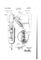
Ancillary objects and features of novelty will become apparent to those skilled in the art, in following the description of the preferred form of the invention, illustrated in the accompanylng drawings, wherein-- Figure 1 is a pictorial view of the invention;
Figure 2 is a side view of the invention, portions being broken away to illustrate details of construction;
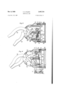
Figure 3 is a sectional view illustrating the jaw actuation mechanism in one operative position;
Figure 4 is a sectional view illustrating the jaw actuation mechanism in a second operative posiillustrating the use :tion;
. Figure 5 is a sectional view taken substantially on the line 5--5 of Figure 4 and in the direction of the arrows, and;
Figure 6 is an elevational fragmentary view illustrating the ratchet means for actuation of the jaw locking means.
A housing I0 is provided of any suitable material, preferably of a very light metal, plastic or the like and is positionable about the lower Anchor means I2 is provided in association with the said housing and is adapted to be secured to the upper part of the arm of an individual. A strap 14 may be associated herewith and a complemental buckle l6 detachably connectable therewith. It is preferable that this portion of the invention be made of some flexible material such as leather or the like.
A pair of rods l8 extend from opposite sides of the anchor means 12 and are preferably retained therein through the medium of small rivets covered by a layer of leather.
A pair of cases 20 and 22 respectively are positioned on opposite sides of the said housing I 0 and terminate in bifurcations 24. Between these bifurcations the terminal portions of the rods l8 are journaled. A suitable pivot pin 26 may be used in association with each of these connections. As is seen in Figure 2 the said cases are formed in two pieces, this being done merely to facilitate manufacture.
Referring now to Figures 3 and 4 it will be seen that a partition 30 is provided in the said housing l0 thereby defining two chambers. In the lower chamber there is provided a mechanism for actuating a pair of jaws. This pair of jaws 32 and 34 respectively may be serrated on the inner surfaces for additional gripping and they are pivoted within the terminal portion of the housing by means of pivot pins 36 and 38. Shoulders 40 and 42 are provided within the said housing In for the purpose of limiting the travel of the jaws.
The inner ends (with respect to the housing) have pivot pins 44 and 46 extending therethrough respectively with a suitable anti-friction bearing seated on each of these pins. A bell crank 48 is pivoted at one end to the said pivot pin 44, while the other end receives a rack gear 50 pivotally thereon.
A spring 52 or some other suitable resilient biasing means is secured to a continuation of the bell crank 48 and more specifically a tab 54 extending from the said crank. The opposite end of the said spring 52 is secured in an aperture at the terminal of the said rack 50, thereby normally biasing the rack to a selected position.
A link 58 is pivoted to the said pivot pin 46 and has a protuberance 60 thereon. The opposite end of the said link 58 is pivoted to a suitable stub shaft 62 which also pivotally maintains the said bell crank 48.
It will be noted that the front or end portion of the housing where the said jaws extend may be detachable if so desired, as illustrated in Figures 3 and 4 in order to facilitate assembly and also to facilitate repair.
Means for actuating the said jaws 32 and 34 respectively is provided. This means maybe seen best by correlating Figures 2, 3 and 4. In each case 20 and 22 respectively there is provided identical structure and therefore, the apparatus in one case will be described in detail, thereby leading to a complete understanding of the apparatus in the opposite case. A cable 66 is secured to the end of the said rod I8 by suitable, conventional cable connector 88. The said cable 86 extends around a pulley 88 which is journaled in the said case, then terminates in a plunger 10 which extends slidably through an opening in the tie rod I0. The said plunger has an enlarged head 12 and a spring 14 surrounding the plunger I which is seated on said head and upon the tie rod I8. This tie rod extends completely through the housing I0 and is guided in a suitable slot 18 therein. It may now be seen that upon pivotal movement of the said housing I0 relative to the anchor means I2, both cables 86 will be moved in one direction urging the tie rod I8 against the opposition of the springs 88 and 80. When the tie rod I8 is operated in this manner the springs I4 are compressed so that they may return the cables 08.
Since the cable 86 and its appurtenant mechanism is duplicated in the opposite case 20, an even pull is provided on the tie rod I8.
A bracket 82 is secured to the said partition 30 and has a suitable aperture therein. Also extending through this bracket is the tie rod I6.
which has a rod 84 rigidly secured thereto. The said rod 84 extends through the aperture in the bracket 82 and is guided thereby. Also, the terminal portion of the said rod 84 is secured to the pivot or stub shaft 82. Seated on the bracket 82 is a spring 88 which also bears against the lower portion of a stub shaft and pivot assembly 82. Of course, this spring normally biases the crank 48 and the link 58 in a selected direction, constantly urging the jaws to an open position.
The pair of springs 88 and 80 respectively are secured to the tie rod I6 and anchored to suitable perches 82 and 84 respectively which are secured to the inner surface of the housing I0. These springs constantly urge the tie rod I6, through the medium of the rod 84 and bracket 82 against the force of the spring 88 and, against the force of the springs I4.
It is now readily apparent that upon pivotal movement of the housing I0 relative to the anchor means, the laws are actuated. In order to maintain the jaws in a selected position the rack 80 is utilized in association with the protuberance 80. A cable 88 is secured to the terminal portion of the said rack 50 and extends around a drum I00 which is positioned in the said housing I0. I This drum has a ratchet gear I02 rigidly secured thereto and a resiliently biased dog I08 engageable with the teeth of the said ratchet gear. The resilient biasing means may be a simple spring I08 and a dog may of course be pivoted in a suitable, conventional bracket. By winding the cable 88 around the drum I00 the rack will always be held in the inoperative position. However, by unwinding the drum I00, the cable 88 will be played out permitting the spring 52 to urge the rack 80 to a position to engage the protuberance 80, thereby locking the pliers or jaws 82 and 84 to the closed position. The spring 86 normally maintains the jaws in the open position however, they may be maintained locked at all times by utility of the rack 50 and proturberance 80,
It is apparent that variations may be made without departing from the spirit of the inven- 4 tion. Accordingly, limitation is sought only in accordance with the scope of the following claims.
Having described the invention, what is claim ed as new is:
1. A mechanical limb comprising a housing adapted to fit around the forearm, anchor means adapted to attach to the upper arm, means for pivotally securing said anchor means to said housing, jaws pivoted in said housing and extending therefrom, means for actuating said jaws by pivotal movement of said housing relative to said anchor means, said pivotal securing means comprising rods secured to said anchor means, enclosure cases secured to said housing, and pivot pins extending through adjacent ends of said cases and said rods.
2. A mechanical limb comprising a housin't adapted to fit around the forearm, anchor meansv adapted to attach to the upper arm, means for pivotally securing said anchor means to said housing, jaws pivoted in said housing and extending therefrom, means for actuating said laws by pivotal movement of said housing relative to said anchor means, including a pivoted crank and link connection between said arms, means associated with said Jaws for retaining said jaws in selected relative positions, including resiliently biased means for latching said jaws in the closed position, said resiliently biased latch means including a spring secured to said crank, a rack pivoted to said crank having said spring secured thereto, and a pin mounted on said link engageable with the teeth of the rack.
3. A mechanical limb comprising a housing adapted to fit around the forearm, anchor means adapted to attach to the upper arm, means for pivotally securing said anchor means to said housing, Jaws pivoted in said housing and extending therefrom, means for actuating said jaws by pivotal movement of said housing relative to said anchor means including a pivoted crank and link connection between said arms, means associated with said Jaws for retaining said jaws in selected relative positions, including resiliently biased means for latching said Jaws in the closed position, said resiliently biased latch means including a spring secured to said crank, a rack pivoted to said crank having said spring secured thereto, a pin mounted on said link engageable with the teeth of the rack, a ratchet having a drum secured thereto secured to the housing, a resiliently biased dog engaging said ratchet, and a cable connecting said rack and said drum.
4. A mechanical limb comprising a housing adapted to fit around the forearm, anchor means adapted to attach to the upper arm, means for pivotally securing said anchor means to said housing, jaws pivoted in said housing and extending therefrom, means for actuating said jaws by pivotal movement of said housing relative to said anchor means including a pivoted crank and link connection between said arms, means associated with said Jaws for retaining said jaws in selected relative positions, including resiliently biased means forlatching said jaws in the closed position, said resiliently biased latch means including a spring secured to said crank, a rack pivoted to said crank having said spring secured thereto, a pin mounted on said link engageable with the teeth of the rack, a ratchet having a drum secured thereto secured to the housing, a resiliently biased dog engaging said ratchet, a cable connecting said rack and said drum, said pivotal securing means comprising rods secured to said anchor means, enclosure cases secured to said 5 6 housing, and pivot pins extending through adja- ITED NTS cent ends of said cases and said rods. UN STATES FATE Number Name Date CLYDE E. PILSON. 1,885,138 P115011 NOV. 1, 1932 5 REFERENCES CITED FOREIGN PATENTS e $0110 1 f rence r of r o d 11 Number Country Date Th w M re 8 s a e r m t 8 155,201 Great Britain Feb. 9, 1922 file of this patent:
Priority Applications (1)
| Application Number | Priority Date | Filing Date | Title |
|---|---|---|---|
| US788433A US2487724A (en) | 1947-11-28 | 1947-11-28 | Artificial arm |
Applications Claiming Priority (1)
| Application Number | Priority Date | Filing Date | Title |
|---|---|---|---|
| US788433A US2487724A (en) | 1947-11-28 | 1947-11-28 | Artificial arm |
Publications (1)
| Publication Number | Publication Date |
|---|---|
| US2487724A true US2487724A (en) | 1949-11-08 |
Family
ID=25144474
Family Applications (1)
| Application Number | Title | Priority Date | Filing Date |
|---|---|---|---|
| US788433A Expired - Lifetime US2487724A (en) | 1947-11-28 | 1947-11-28 | Artificial arm |
Country Status (1)
| Country | Link |
|---|---|
| US (1) | US2487724A (en) |
Cited By (5)
| Publication number | Priority date | Publication date | Assignee | Title |
|---|---|---|---|---|
| US4089379A (en) * | 1977-01-19 | 1978-05-16 | Crownover Frederick S | Glove and tool device |
| US4203495A (en) * | 1977-01-19 | 1980-05-20 | Crownover Frederick S | Glove and tool device with two tool elements |
| US4291421A (en) * | 1979-10-01 | 1981-09-29 | Lester T. Stormon | Hand and forearm prostheses |
| US4685924A (en) * | 1985-10-04 | 1987-08-11 | Massey Peyton L | Prehensile thumb and finger prosthesis |
| US20100161078A1 (en) * | 2008-12-20 | 2010-06-24 | United States Army, As Represented By The Secretary Of The Army | Simplified prosthetic device |
Citations (2)
| Publication number | Priority date | Publication date | Assignee | Title |
|---|---|---|---|---|
| GB155201A (en) * | 1919-12-08 | 1922-02-09 | Ersatzglieder Ges Sauerbruch G | An improved artificial hand |
| US1885138A (en) * | 1929-09-20 | 1932-11-01 | Pilson Sam | Mechanical arm |
-
1947
- 1947-11-28 US US788433A patent/US2487724A/en not_active Expired - Lifetime
Patent Citations (2)
| Publication number | Priority date | Publication date | Assignee | Title |
|---|---|---|---|---|
| GB155201A (en) * | 1919-12-08 | 1922-02-09 | Ersatzglieder Ges Sauerbruch G | An improved artificial hand |
| US1885138A (en) * | 1929-09-20 | 1932-11-01 | Pilson Sam | Mechanical arm |
Cited By (5)
| Publication number | Priority date | Publication date | Assignee | Title |
|---|---|---|---|---|
| US4089379A (en) * | 1977-01-19 | 1978-05-16 | Crownover Frederick S | Glove and tool device |
| US4203495A (en) * | 1977-01-19 | 1980-05-20 | Crownover Frederick S | Glove and tool device with two tool elements |
| US4291421A (en) * | 1979-10-01 | 1981-09-29 | Lester T. Stormon | Hand and forearm prostheses |
| US4685924A (en) * | 1985-10-04 | 1987-08-11 | Massey Peyton L | Prehensile thumb and finger prosthesis |
| US20100161078A1 (en) * | 2008-12-20 | 2010-06-24 | United States Army, As Represented By The Secretary Of The Army | Simplified prosthetic device |
Similar Documents
| Publication | Publication Date | Title |
|---|---|---|
| US4034542A (en) | Fruit picking implements | |
| US3978605A (en) | Floating fish grip | |
| US2487724A (en) | Artificial arm | |
| US2409884A (en) | Artificial arm and hand | |
| US2680842A (en) | Pull cord actuated electric switch | |
| US2285885A (en) | Mechanical hand | |
| JPS62500071A (en) | fishing equipment | |
| US4171589A (en) | Snare type animal trap | |
| US2470941A (en) | Fish stringer | |
| US1818474A (en) | Gaff hook | |
| US4836815A (en) | Emergency illuminated lifeline | |
| US4173210A (en) | Bow string release device | |
| US3707800A (en) | Fish mouth spreader and holder | |
| US2433301A (en) | Mechanically operated thumb for artificial hands | |
| US2537551A (en) | Mechanical hand | |
| US1500613A (en) | Fish-stringing device | |
| US1649045A (en) | Figure toy | |
| US1740230A (en) | Artificial limb | |
| US4400902A (en) | Automatic fishing apparatus | |
| US2277343A (en) | Wire bending, clinching, and cutting tool | |
| US4117961A (en) | Device for opening or closing a zipper | |
| US1422714A (en) | Jointed artificial hand | |
| US4169333A (en) | Model aircraft launcher | |
| US2414179A (en) | Woodpecker toy | |
| US1362793A (en) | Artificial hand |