US2487182A - Two-temperature refrigerator having means for defrosting - Google Patents
Two-temperature refrigerator having means for defrosting Download PDFInfo
- Publication number
- US2487182A US2487182A US728492A US72849247A US2487182A US 2487182 A US2487182 A US 2487182A US 728492 A US728492 A US 728492A US 72849247 A US72849247 A US 72849247A US 2487182 A US2487182 A US 2487182A
- Authority
- US
- United States
- Prior art keywords
- evaporator
- compartment
- temperature
- freezing
- chamber
- Prior art date
- Legal status (The legal status is an assumption and is not a legal conclusion. Google has not performed a legal analysis and makes no representation as to the accuracy of the status listed.)
- Expired - Lifetime
Links
Images
Classifications
-
- F—MECHANICAL ENGINEERING; LIGHTING; HEATING; WEAPONS; BLASTING
- F25—REFRIGERATION OR COOLING; COMBINED HEATING AND REFRIGERATION SYSTEMS; HEAT PUMP SYSTEMS; MANUFACTURE OR STORAGE OF ICE; LIQUEFACTION SOLIDIFICATION OF GASES
- F25D—REFRIGERATORS; COLD ROOMS; ICE-BOXES; COOLING OR FREEZING APPARATUS NOT OTHERWISE PROVIDED FOR
- F25D11/00—Self-contained movable devices, e.g. domestic refrigerators
- F25D11/02—Self-contained movable devices, e.g. domestic refrigerators with cooling compartments at different temperatures
- F25D11/022—Self-contained movable devices, e.g. domestic refrigerators with cooling compartments at different temperatures with two or more evaporators
-
- Y—GENERAL TAGGING OF NEW TECHNOLOGICAL DEVELOPMENTS; GENERAL TAGGING OF CROSS-SECTIONAL TECHNOLOGIES SPANNING OVER SEVERAL SECTIONS OF THE IPC; TECHNICAL SUBJECTS COVERED BY FORMER USPC CROSS-REFERENCE ART COLLECTIONS [XRACs] AND DIGESTS
- Y10—TECHNICAL SUBJECTS COVERED BY FORMER USPC
- Y10S—TECHNICAL SUBJECTS COVERED BY FORMER USPC CROSS-REFERENCE ART COLLECTIONS [XRACs] AND DIGESTS
- Y10S62/00—Refrigeration
- Y10S62/13—Insulation
Definitions
- the present invention relates to-refrigerators
- Another object of the invention is the provision of a refrigerator of the class described, in which there is a separate compartment for freezing foods and maintaining them at a temperature below freezing and another compartment adapted to be maintained at a temperature above freezing and adapted to be maintained at a predetermined humidity so that the food stored in the latter compartment may not be dried out.
- Another object of the invention is the provision of an improved refrigerator construction, in which the freezing compartment is located in the lowermost part of the cabinet and the moderately cooled, food storage compartment is located in the upper part of the cabinet, each compartment having its own separate door so that only the one to which access is desired need be opened, but when both are opened for transfer of food from one to the other, there will-be no tendency for the cold air in the lower compartment to spill out and pass into the upper compartment or vice versa, as the warmer air is already above and the colder air is already below.
- Another object of the invention is the provision of an improved method of controlled dehydration which results in the continuous dehydration of the insulation, removal of frost from the walls of the lower freezing compartment, and removal of a predetermined amount of moisture from the air of the upper humid compartment so as to avoid excessive humidity by causing the excess moisture to accumulate upon a special dehydration coil operated at a lower temperature than either evaporator.
- Another object of the invention' is the provision of an improved refrigerator construction of the class described which is simple, which may be manufacture economically, which is adapted b6 2 to be serviced readily and which is adapted to maintain a uniform temperature throughout each compartment, and in some embodiments which is provided with a removable refrigeration apparatus.
- Another object of the invention is the provision of an improved two-temperature refrigerator having a low humidity freezing compartment and a high humidity food storage compartment in which these chambers are cooled by means of a plurality of evaporators or parts of an evaporator arranged in series and located on the walls of the liners so as to effect a uniform cooling action throughout both of the compartments, and in'which a third series evaporator or portion of the evaporator is provided for effecting a partial dehydration in the high humidity compartment so as to avoid excessive humidity.
- Another object of the invention is the provision of an improved refrigerator having two compartments comprising an upper chamber in which the air is cooled to substantially 40 F., and a ,lower freezing chamber in which the air is cooled to a temperature below 0 F., each of said compartments being provided with an evaporator located to effect uniform cooling throughout the compartment, and the upper food storage chamber being provided with a dehydration evaporator coil in series with the other evaporator, the said dehydration coil being located low in the upper chamber near the coolest air of the chamber and being operated at from 10 F. to -15 F. 'to dehumidify by frosting during operation of the unit.
- Another object of the invention is the provision of an improved refrigerator apparatus of the class described, including provision for defrosting the dehydration coil, the said means consisting of a bypass conduit and a shut-off valve whereby the bypass conduit may be opened and the conduit leading to the dehydration coil may be closed to bypass the refrigerant around said dehydration coil to effect the defrosting.
- Fig. l is a diagrammatic elevational view of the refrigeration system
- Fig. 2 is a vertical sectional view taken on the plane of the line 2-2 of Fig. 3'looklng in the direction of the arrows;
- Fig. 3 is a front elevational view of the refrigerator with the doors, shelves and other internal equipment removed.
- the present refrigeration apparatus preferably includes a motor compressor In of the sealed type, a condenser II and a float controlled valve chamber l2 for compressing, con densing and controlling the flow of refrigerant.
- the condenser II is connected to the outlet of the motor compressor and in turn has its outlet connected to the inlet of the float chamber l2.
- the cooling evaporators are preferably three in number, comprising evaporator 13 for cooling the lower below freezing chamber It for freezing foods and storing them, a second evaporator l4 for cooling the upper high humidity above freezing chamber l1, and a third evaporator I5 which is for partialldehydration of the air in the upper high humidity compartment.
- the lower compartment l5 has its coils operated at a suitable temperature so as to cool the air in this compartment to a temperature below freezing and to freeze food for storage. This inevitably results in the dehydration of the air in the lower freezing chamber l6 as the moisture in the air is frozen out in the from of frost.
- the upper chamber I! for storage of food at above freezing temperatures may have its coil operated at about 35 F. to cool the air to about 40 F. As this is above freezing the moisture in 'the air will not be condensed, but since the air which comes to this chamber from the outside contains a certain amount of moisture, its relative humidity is greatly increased inside chamber II when its temperature is reduced thereby tending toward excessive humidity.
- the dehydration coil I5 is operated below freezing and is located in the upper chamber l1, preferably on the lower back wall so that it will be near the coolest air in this chamber. This coil dehumidifles the air in the chamber l1 partially by condensing moisture out of the air in chamber I! in the form of frost whenever the motor compressor is operating.
- the refrigerant is conducted from the float valve chamber l2 through a relatively small diameter conduit l8 to the evaporator M for the upper warmer high humidity chamber I1, being introduced into the evaporator I 4 at its lowermost portion IS.
- a conduit 20 leads from the uppermost part 2
- a conduit 24 leads from the uppermost part 25 of evaporator l3 to a second spring-pressed differential valve 25 and thence to the lowermost part 21 of dehydration coil [5.
- the uppermost part 28 of evaporator is connected to an accumulator 29 which may take the form of a header.
- the accumulator 29 is connected to the vapor take-off pipe 30, which is a relatively large pipe leading from header 29 to the inlet of the motor compressor l0.
- indicates the thermostatic bulb of a thermostatic switch which is to be actuated responsive to the temperature of the' header 29, and this thermostatic bulb is, therefore, located in the chamber H, the high humidity warmer food storage chamber 3m and 3lb indicate electrical conductors leading from the thermostatic switch shown diagrammatically at 3
- the conductor 3Ia leads directly to the motor compressor, while conductor 31b leads to one of the line conductors.
- Conductor 3lc extends from the line to the motor compressor.
- a bypass conduit 32 extends from conduit 24 to header 29 and is provided with a shut-oil. valve 33. When the valve 33 is closed, the bypass 32 is without effect and the three evaporators l4, l3 and I5 are operated in series, as shown.
- the refrigerant takes the easiest path comprising the bypass conduit 32, and no refrigerant passes the spring pressed differential valve 26 as there is no suction on it to open it.
- the dehydration coil l5 may be defrosted at will by opening the valve 33 in the bypass conduit 32.
- the cabinet 35 indicates in its entirety the cabinet which is preferably substantially rectangular in side elevation, in front elevation and in plan, but provided with rounded corners.
- the cabinet 35 may consist of an outer shell 36 having a top wall 31, back wall 33, two side walls 33, 40, front wall 4 I and bottom wall 42.
- is provided with a pair of openings 43, 44, each opening being substantially coextensive in size with the front projected area of its corresponding chamber 11 and I5 respectively.
- the chamber I1 is formed by means of a sheet metal liner indicated in its entirety by the numeral 45 and having a top wall 46. a back wall 41, a bottom wall 48 and the two side walls 49 and 5D.
- Liner 45 has its forward opening surrounded by an attaching flange 5
- the lower freezing chamber I6 is formed by means of the metal liner 54 which has a top wall 55, back wall 56, bottom wall 51 and side walls 58, 59.
- the liner 54 is provided with an outwardly flaring attaching flange 60, which is secured to insulating fibre breaker strips 6
- the dimensions of the upper liner 4'! are such with respect to the size of shell 35 that the space between them, when filled with suitable insulation such as cork or rock-wool, provides insulation adequate to maintain the temperature differential between the inside and the outside of this compartment.
- the partition 63 between the compartments l6 and I1 is formed by the liner walls 43 and 55 and a filling of the same insulation, and may be of a suitable thickness to maintain the temperature differential between the two chambers.
- the evaporator coils l3 and I4 are both preferably uniformly distributed upon the side walls and back of the liner of each compartment. They are also preferably so arranged that the coils slope upward continuously as they extend backward and forward across one side wall to the back and the other side wall where they form a U-bend and then again slope upwardly and backwardly on the latter side wall.
- the evaporator l3 for the freezing chamber I8 is also preferably provided with a portion 65 which extends backward and forward in sinuous fashion across the outside of the bottom wall 51 of the liner 54.
- Another section 66 of evaporator i3 is provided for cooling the top wall 55 of liner 54.
- the dehydration coil l5 may be mounted upon a sheet of metal 61 in sinuous fashion and provided with the larger header 29 at the top, or this unit may be constructed of two sheets of metal stamped with grooves corresponding in shape to the conduits i5 and header 29, the sheets being welded together between the conduits and completely about the periphery to form a liquid tight sealed unit.
- Transverse fins '68 may be secured to the sheet or sheets 61, and may have a tapered and pointed lower edge 69 adapted to deposit moisturein a trough ll! when defrosted.
- the trough l0 discharges into a sloping conduit 'li extending along inside partition 63 and laterally to the space between side wall 39 of the shell and side wall 58 of the lower liner (Fig. 3) where it may discharge into a suitable removable receptacle 12 by means of a downwardly extending conduit 13.
- Shell wall 39 maybe provided with a suitable door 14 for removal of the drip receptacle 12.
- the pipes leading to the various evaporators and connecting them are preferably all disposed inside the insulation between the liner and'the outer shell.
- the cabinet may be provided with a machine compartment 15 located below the bottom Wall 42 of the shell 36.
- may extend down-- wardly to the floor and may be provided with laterally turned flanges I6 forming a base.
- Front wall II is preferably provided with louvers I! in that portion which is located below the opening 44 to provide for inlet of air from the front to the machine compartment 15. Additional louvers may be provided in the front door at the point as indicated in the fragmentary showing of the door 18 having louvers 19.
- the shell 36 may be formed with a partially spherical depression 80 at the lower rear corner for housing a part of the motor compressor III, which is located with substantially half of the compressor l0 under the cabinet 35 and half projecting rearwardly thereof.
- Float valve chamber l2 may be disposed beside the motor compressor In in the bell-shaped opening provided by the stamped depression 80.
- Condenser II is mounted upon suitable side frame members 8
- Motor compressor I0, condenser II and float valve chamber [2 may be mounted upon a suitable frame or drawer removably supported upon the flanges 16 so that the compressing and condensing and flow control units may be removed as one unit by disconnecting the pipes at 82, 83.
- the heat of the motor compressor unit l0 causes heated air to move upwardly outside the bell-shaped opening 80, and the heat of the condenser Il causes air to mount upwardly into the bell-shaped opening 80 which acts as a,chimney, thus air is sucked in the front louvers l1, 19
- the lower compartment will be uniformly cooled on all of its sides except the door to a temperature of approximately -5 F., thus maintaining the air at practicallyi0 F.
- High humidity compartment II will have its evaporator at substantially 35 F. thus cooling the air to approximately 40 F.
- tion coil i5 will have its coil at a temperature of 10 F. to -15 F. This coil will accumulate frost and will effect a predetermined amount of dehydration in the upper high humidity chamber II. It will also dehydrate the insulation, prevent frost formation in the freezing or 0 F. compartment, and it can be defrosted by opening the bypass valve while the rest of the system Thus it will never be necessary to shut off the evaporators which cool the two compartments in order to accomplish a defrosting, and the food stored therein may'be continuously kept at a proper temperature in both compartments.
- the operation of the dehydration coil l5 at 10 F. to 15 F., in dehydrating the insulation and defrosting the freezing compartment and controlling the humidity of the high humidity compartment is based upon the fact that in such a system the moisture will eventually flnd its way to the coldest part of the system, even though it is at some intermediate time disposed upon another surface. migration of air from one compartment to another to a predetermined extent the breaker strips should not be sealed against the liner or shell or both.
- the third and coldest evaporator of limited size to limit the amount of dehydration may be located in the insulation between the liner and the shell or between the two liners in the partition.
- a thermostat for controlling the operation of the motor compressor responsive to temperature conditions at said third evaporator for causing an intermittent operation of the compressor and intermittent subzero cooling of said third evaporator, the, said third evaporator frosting and melting alternately, for effecting a continuous defrosting of the freezing compartment, the compartments having access to the space between the inner and outer shells, for dehydration of insulation and for controlling the humidity of the high humidity compartment.
- a refrigeration system the combination of a motor compressor, condenser and flow control device, with a first evaporator connected to receive refrigerant first from the flow control device for cooling a high temperature compartment and a second evaporator receiving the refrigerant next from the first mentioned evaporator through a restriction for establishing a suitable differential in temperature, said second evaporator cooling 2. below-freezing chamber for freezing and storage of frozen foods, and a third evaporator receiving refrigerant from the last mentioned evaporator and operating at a below 0 F.
- a refrigeration system the combination of a motor compressor, condenser and flow control device, with a first evaporator connected to receive refrigerant first from the flow control device for cooling a high temperature compartment and a.
- second evaporator receiving the refrigerant next from the first mentioned evaporator through a restriction for establishing a suitable differential in temperature, said second evaporator cooling a below-freezing chamber for freezing and storage of frozen foods, and a third evaporator receiving refrigerant from the last mentioned evaporator and operating at a below 0 F.
- thermosensitive means for controlling the operation of the motor compressor, and. controlled by the temperature of a portion of said third evaporator.
- a refrigeration system the combination of a motor compressor, condenser and flow control device, with a first evaporator connected to receive refrigerant first from the flow control device for cooling a high temperature compartment and a second evaporator receiving the refrigerant next from the first mentioned evaporator through a restriction for establishing a suitable differential in temperature, said second evaporator cooling a below-freezing chamber for freezing and storage of frozen foods, a third evaporator receiving refrigerant from the last mentioned evaporator and operating at a below 0 F.
- a thermostat for controlling the operating of the motor compressor responsive to temperature conditions at said third evaporator for causing an intermittent operation of the compressor and intermittent subzero cooling of said third evaporator, the said third evaporator frosting and melting alternately, for effecting a continuous defrostin of the freezing compartment, the said compartments having access to the space between the inner and outer shells, for dehydration of insulation and for controlling the humidity of the high humidity compartment, said third evaporator being located in the high humidity compartment.
- a refrigeration system the combination of a motor compressor, condenser and flow control device, with a first evaporator connected to receive refrigerant first from the flow control device for cooling a high-temperature compartment and a second evaporator receiving the refrigerant next from the first mentioned evaporator through a restriction for establishing a suitable diiferential in temperature, said second evaporator cooling a below-freezing chamber for freezing and storage of frozen foods, and a third evaporator receiving refrigerant from the last mentioned evaporator and operating at a below 0 F. temperature in one of said compartments for effecting a continuous defrosting of the freezing compartment.
- said means comprising a bypass conduit for bypassing the third evaporator while the other two evaporators are operating.
- a refrigeration system the combination of a motor compressor, condenser and flow control device, with a first evaporator connected to receive refrigerant first from the flow control device for cooling a high-temperature compartment and a second evaporator receivin the refrigerant next from the first mentioned evaporator through a restriction for establishing a suitable differential in temperature, said second evaporator cooling a below-freezing chamber for freezing and storage of frozen foods, and a third'evaporator receiving refrigerant from the last mentioned evaporator and operating at a below 0 F.
- said means comprising a bypass conduit for bypassing the third evaporator while the other two evaporators are operating, said bypass conduit having a manually actuated valve which may be opened to make the bypass effective or closed to make the third evaporator operate.
- a cablnet provided with an outer shell, an inner liner forming an upper high humidity compartment and a second liner forming a lower freezing com- 1 partment, the said compartments having access thermostatic means for controlling said compressing unit responsive to temperature conditions at said third evaporator to cause intermittent operation of said compressing unit, and
- a cabinet provided with an outer shell, an inner liner forming an upper high humidity compartment and a lower liner forming a lower freezing compartment, a compressing and condensing unit and a pair of evaporators, one for each compartment, said evaporators being located in heat conducting contact with the outside of the liners of said compartments, and means for continuously dehydrating the insulation between said shell and liners and for continuously defrosting the lower freezing compartment while both evaporators are operating, said means comprising a third evaporator operated at a lower temperature I than either of the first mentioned two evaporators, and bypass means for bypassing said third evaporator whereby it may be defrosted while the other two evaporators operate.
- a cabinet provided with an outer shell, an inner liner forming an upper high humidity compartment and a lower liner forming a lower freezing compartment, a compressing and condensing unit and a pair of evaporators, one for each compartment, said evaporators being located in heat conducting contact with the outside of the liners of said compartments, and means for continuously dehydrating the insulation between said shell and liners and for continuously defrosting the lower freezing compartment while both evaporators are operating, said means comprising a third evaporator operated at a lower temperature than either of the first mentioned two evaporators, and bypass means for bypassing said third evaporator whereby it may be defrosted while the other two evaporators operate, and means for collecting the condensate from the defrosting of said third evaporator.
- a refrigerator the combination of an outer shell, which is forwardly open, with a pair of inner liners also forwardly open, and breaker strips for joining the forward edges of each inner liner to the outer shell, said breaker strips being unsealed and permitting access of air from the compartments in said liners to the space between the liners and the outer shell for dehydrating the insulation, a first evaporator for cooling a lower freezing compartment formed by one liner, and a second evaporator for cooling the upper storage compartment formed by'the other liner, the latter being cooled to a temperature above freezing, and the-former to a temperature below freezing,
- a third evaporator located in the storage chamber, and being maintained at a temperature colder than either of the other evaporators and a thermostat for controlling the supply of refrigerant responsive to temperature conditions at said third evaporator to cause intermittent frosting and melting at said third evaporator, for dehydrating the insulation and defrosting the lower evaporator and liner continuously.
- a refrigerator the combination of an outer shell, which is forwardly open, with a pair of inner liners also forwardly open, and breaker strips for joining the forward edges of each inner liner to the outer shell, said breaker strips being unsealed and permitting access of air from the compartments in said liners to the space between the liners and the outer shell for dehydrating the insulation, a first evaporator for cooling a lower freezing compartment formed by one liner, and a second evaporator for cooling the upper storage compartment formed by the other liner, the latter being cooled to a temperature above freezing, and the former to a temperature below freezing, and a third evaporator located in the storage chamber, and being maintained at a temperature colder than either of the other evaporators for dehydrating the insulation and defrosting the lower evaporator and liner continuously, the said third evaporator being located close to the bottom of the food storage chamber, whereby it is adapted to effect a predetermined limited dehydration of the food storage compartment.
- said means comprising a by-pass con- 10 2,411,461 duit closed by a valve, which may be opened to 2,432,042 by-pass the third evaporator.
Description
Nov. 8, 1949 w. E. RICHARD TWO-TEMPERATURE REFRIGERATOR HAVING MEANS FOR DEFROSTING 2 Sheets-Sheet 1 Filed Feb. 14, 1947 I 1/ 9 I 1/ I l/ l/ v A INVENTOR.
BY ,ZQ/KW Nov. 8, 1949 w. E. RICHARD TWO-TEMPERATURE REFRIGERATOR HAVING MEANS FOR DEFROSTING -2 Sheets-Sheet 2 Filed Feb. 14, 1947 IN V EN TOR.
u I I v V J mwwm BY ,lw 4M its Patented Nov. 1949 TWO-T ERATURE REFRIGERATOR HAVIN MEANS FOR DEFROSTING William E. Richard, Evansville, Ind., asslgnor to Seeger Refrigerator Company, a corporation of esota Application February 14, 1947, Serial No. 728,492
13 Claims.
The present invention relates to-refrigerators,
' and is particularlv concerned with a refrigerator l of mechanism, and in which the refrigeration mechanism may be embodied in a removable unit occupying a minimum amount of spac and adapted to be removed from or inserted in the back of the cabinet.
Another object of the invention is the provision of a refrigerator of the class described, in which there is a separate compartment for freezing foods and maintaining them at a temperature below freezing and another compartment adapted to be maintained at a temperature above freezing and adapted to be maintained at a predetermined humidity so that the food stored in the latter compartment may not be dried out.
Another object of the invention is the provision of an improved refrigerator construction, in which the freezing compartment is located in the lowermost part of the cabinet and the moderately cooled, food storage compartment is located in the upper part of the cabinet, each compartment having its own separate door so that only the one to which access is desired need be opened, but when both are opened for transfer of food from one to the other, there will-be no tendency for the cold air in the lower compartment to spill out and pass into the upper compartment or vice versa, as the warmer air is already above and the colder air is already below.
Another object of the invention is the provision of an improved method of controlled dehydration which results in the continuous dehydration of the insulation, removal of frost from the walls of the lower freezing compartment, and removal of a predetermined amount of moisture from the air of the upper humid compartment so as to avoid excessive humidity by causing the excess moisture to accumulate upon a special dehydration coil operated at a lower temperature than either evaporator.
Another object of the invention'is the provision of an improved refrigerator construction of the class described which is simple, which may be manufacture economically, which is adapted b6 2 to be serviced readily and which is adapted to maintain a uniform temperature throughout each compartment, and in some embodiments which is provided with a removable refrigeration apparatus.
Another object of the invention is the provision of an improved two-temperature refrigerator having a low humidity freezing compartment and a high humidity food storage compartment in which these chambers are cooled by means of a plurality of evaporators or parts of an evaporator arranged in series and located on the walls of the liners so as to effect a uniform cooling action throughout both of the compartments, and in'which a third series evaporator or portion of the evaporator is provided for effecting a partial dehydration in the high humidity compartment so as to avoid excessive humidity.
Another object of the invention is the provision of an improved refrigerator having two compartments comprising an upper chamber in which the air is cooled to substantially 40 F., and a ,lower freezing chamber in which the air is cooled to a temperature below 0 F., each of said compartments being provided with an evaporator located to effect uniform cooling throughout the compartment, and the upper food storage chamber being provided with a dehydration evaporator coil in series with the other evaporator, the said dehydration coil being located low in the upper chamber near the coolest air of the chamber and being operated at from 10 F. to -15 F. 'to dehumidify by frosting during operation of the unit.
Another object of the invention is the provision of an improved refrigerator apparatus of the class described, including provision for defrosting the dehydration coil, the said means consisting of a bypass conduit and a shut-off valve whereby the bypass conduit may be opened and the conduit leading to the dehydration coil may be closed to bypass the refrigerant around said dehydration coil to effect the defrosting.
Other objects and advantages of the invention will be apparent from the following description and the accompanying drawings, in which similar characters of reference indicate similar parts throughout the several views.
Referring to the drawings of which there are two sheets,
Fig. l is a diagrammatic elevational view of the refrigeration system,
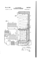
Fig. 2 is a vertical sectional view taken on the plane of the line 2-2 of Fig. 3'looklng in the direction of the arrows; and
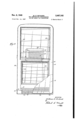
Fig. 3 is a front elevational view of the refrigerator with the doors, shelves and other internal equipment removed.
Referring to Fig. 1, the present refrigeration apparatus preferably includes a motor compressor In of the sealed type, a condenser II and a float controlled valve chamber l2 for compressing, con densing and controlling the flow of refrigerant. The condenser II is connected to the outlet of the motor compressor and in turn has its outlet connected to the inlet of the float chamber l2. The cooling evaporators are preferably three in number, comprising evaporator 13 for cooling the lower below freezing chamber It for freezing foods and storing them, a second evaporator l4 for cooling the upper high humidity above freezing chamber l1, and a third evaporator I5 which is for partialldehydration of the air in the upper high humidity compartment.
The lower compartment l5 has its coils operated at a suitable temperature so as to cool the air in this compartment to a temperature below freezing and to freeze food for storage. This inevitably results in the dehydration of the air in the lower freezing chamber l6 as the moisture in the air is frozen out in the from of frost.
The upper chamber I! for storage of food at above freezing temperatures may have its coil operated at about 35 F. to cool the air to about 40 F. As this is above freezing the moisture in 'the air will not be condensed, but since the air which comes to this chamber from the outside contains a certain amount of moisture, its relative humidity is greatly increased inside chamber II when its temperature is reduced thereby tending toward excessive humidity.
The dehydration coil I5 is operated below freezing and is located in the upper chamber l1, preferably on the lower back wall so that it will be near the coolest air in this chamber. This coil dehumidifles the air in the chamber l1 partially by condensing moisture out of the air in chamber I! in the form of frost whenever the motor compressor is operating.
Between intermittent operations of the motor compressor a certain amount of the frost may be melted off the dehydration coil 15, but it may be necessary periodically to defrost this coil and provision is made for this purpose as follows:
The refrigerant is conducted from the float valve chamber l2 through a relatively small diameter conduit l8 to the evaporator M for the upper warmer high humidity chamber I1, being introduced into the evaporator I 4 at its lowermost portion IS. A conduit 20 leads from the uppermost part 2| of evaporator l4 to the lowermost part 22 of evaporator I3, and a springpressed differential valve 23 is interposed between these evaporators l4 and I3 to maintain a differential in pressure, that is, in the suction pressure between these two evaporators so that one (I4) may be operated at 35 F. and the other (l3) may be operated at to F.
A conduit 24 leads from the uppermost part 25 of evaporator l3 to a second spring-pressed differential valve 25 and thence to the lowermost part 21 of dehydration coil [5. The uppermost part 28 of evaporator is connected to an accumulator 29 which may take the form of a header. The accumulator 29 is connected to the vapor take-off pipe 30, which is a relatively large pipe leading from header 29 to the inlet of the motor compressor l0.
3| indicates the thermostatic bulb of a thermostatic switch which is to be actuated responsive to the temperature of the' header 29, and this thermostatic bulb is, therefore, located in the chamber H, the high humidity warmer food storage chamber 3m and 3lb indicate electrical conductors leading from the thermostatic switch shown diagrammatically at 3|, which controls the motor compressor III. The conductor 3Ia leads directly to the motor compressor, while conductor 31b leads to one of the line conductors. Conductor 3lc extends from the line to the motor compressor.
A bypass conduit 32 extends from conduit 24 to header 29 and is provided with a shut-oil. valve 33. When the valve 33 is closed, the bypass 32 is without effect and the three evaporators l4, l3 and I5 are operated in series, as shown.
When the valve 33 is opened the refrigerant takes the easiest path comprising the bypass conduit 32, and no refrigerant passes the spring pressed differential valve 26 as there is no suction on it to open it. Thus the dehydration coil l5 may be defrosted at will by opening the valve 33 in the bypass conduit 32.
Referring to Fig. 2, 35 indicates in its entirety the cabinet which is preferably substantially rectangular in side elevation, in front elevation and in plan, but provided with rounded corners. The cabinet 35 may consist of an outer shell 36 having a top wall 31, back wall 33, two side walls 33, 40, front wall 4 I and bottom wall 42.
The front wall 4| is provided with a pair of openings 43, 44, each opening being substantially coextensive in size with the front projected area of its corresponding chamber 11 and I5 respectively. The chamber I1 is formed by means of a sheet metal liner indicated in its entirety by the numeral 45 and having a top wall 46. a back wall 41, a bottom wall 48 and the two side walls 49 and 5D.
Liner 45 has its forward opening surrounded by an attaching flange 5| which is secured to a breaker strip 52 of insulating fibre board, which in turn is secured to an inwardly extending attaching flange 53 located about the full periphery of door opening 43 and carried by outer shell 35.
The lower freezing chamber I6 is formed by means of the metal liner 54 which has a top wall 55, back wall 56, bottom wall 51 and side walls 58, 59. At the door opening 44 the liner 54 is provided with an outwardly flaring attaching flange 60, which is secured to insulating fibre breaker strips 6| carried by an inwardly extending attaching flange 62 which extends about the full periphery of the door opening 44, and is carried by the front wall 4| of outer shell 36.
The dimensions of the upper liner 4'! are such with respect to the size of shell 35 that the space between them, when filled with suitable insulation such as cork or rock-wool, provides insulation adequate to maintain the temperature differential between the inside and the outside of this compartment.
The partition 63 between the compartments l6 and I1 is formed by the liner walls 43 and 55 and a filling of the same insulation, and may be of a suitable thickness to maintain the temperature differential between the two chambers.
The evaporator coils l3 and I4 are both preferably uniformly distributed upon the side walls and back of the liner of each compartment. They are also preferably so arranged that the coils slope upward continuously as they extend backward and forward across one side wall to the back and the other side wall where they form a U-bend and then again slope upwardly and backwardly on the latter side wall.
The evaporator l3 for the freezing chamber I8 is also preferably provided with a portion 65 which extends backward and forward in sinuous fashion across the outside of the bottom wall 51 of the liner 54. Another section 66 of evaporator i3 is provided for cooling the top wall 55 of liner 54.
The dehydration coil l5 may be mounted upon a sheet of metal 61 in sinuous fashion and provided with the larger header 29 at the top, or this unit may be constructed of two sheets of metal stamped with grooves corresponding in shape to the conduits i5 and header 29, the sheets being welded together between the conduits and completely about the periphery to form a liquid tight sealed unit.
Transverse fins '68 may be secured to the sheet or sheets 61, and may have a tapered and pointed lower edge 69 adapted to deposit moisturein a trough ll! when defrosted. The trough l0 discharges into a sloping conduit 'li extending along inside partition 63 and laterally to the space between side wall 39 of the shell and side wall 58 of the lower liner (Fig. 3) where it may discharge into a suitable removable receptacle 12 by means of a downwardly extending conduit 13. Shell wall 39 maybe provided with a suitable door 14 for removal of the drip receptacle 12.
The pipes leading to the various evaporators and connecting them are preferably all disposed inside the insulation between the liner and'the outer shell.
which passes upwardly and outwardly of the back of the machine compartment 15.
. be the coldest and the evaporator i3 will be next coldest, while evaporator M will be least cold continues to function.
At its lower end the cabinet may be provided with a machine compartment 15 located below the bottom Wall 42 of the shell 36. Side walls 39, and front wall 4| may extend down-- wardly to the floor and may be provided with laterally turned flanges I6 forming a base. Front wall II is preferably provided with louvers I! in that portion which is located below the opening 44 to provide for inlet of air from the front to the machine compartment 15. Additional louvers may be provided in the front door at the point as indicated in the fragmentary showing of the door 18 having louvers 19.
The shell 36 may be formed with a partially spherical depression 80 at the lower rear corner for housing a part of the motor compressor III, which is located with substantially half of the compressor l0 under the cabinet 35 and half proiecting rearwardly thereof.
Float valve chamber l2 may be disposed beside the motor compressor In in the bell-shaped opening provided by the stamped depression 80. Condenser II is mounted upon suitable side frame members 8| and provided with fins of the same size, and preferably located diagonally across the machine compartment so as to cause all the air which passes from the front to the back to pass through the condenser H.
Motor compressor I0, condenser II and float valve chamber [2 may be mounted upon a suitable frame or drawer removably supported upon the flanges 16 so that the compressing and condensing and flow control units may be removed as one unit by disconnecting the pipes at 82, 83.
The operation of the mechanism in the machine compartment, from point of view of cooling is as follows: i
The heat of the motor compressor unit l0 causes heated air to move upwardly outside the bell-shaped opening 80, and the heat of the condenser Il causes air to mount upwardly into the bell-shaped opening 80 which acts as a,chimney, thus air is sucked in the front louvers l1, 19
depending, of course, upon the amount of charge which is placed in the system and whether there is liquid refrigerant left to evaporate when it reaches the dehydration coil i5. Enough refrigerant should be provided for this purpose.
By means of the present apparatus the lower compartment will be uniformly cooled on all of its sides except the door to a temperature of approximately -5 F., thus maintaining the air at practicallyi0 F.
High humidity compartment II will have its evaporator at substantially 35 F. thus cooling the air to approximately 40 F. tion coil i5 will have its coil at a temperature of 10 F. to -15 F. This coil will accumulate frost and will effect a predetermined amount of dehydration in the upper high humidity chamber II. It will also dehydrate the insulation, prevent frost formation in the freezing or 0 F. compartment, and it can be defrosted by opening the bypass valve while the rest of the system Thus it will never be necessary to shut off the evaporators which cool the two compartments in order to accomplish a defrosting, and the food stored therein may'be continuously kept at a proper temperature in both compartments.
So far as I am aware this is the first refrigeration system in which continuous defrosting of the insulation and of both the freezing and the high humidity compartment is accomplished without interrupting the cooling apparatus and without raising the temperature of the food stored in either compartment.
The operation of the dehydration coil l5 at 10 F. to 15 F., in dehydrating the insulation and defrosting the freezing compartment and controlling the humidity of the high humidity compartment is based upon the fact that in such a system the moisture will eventually flnd its way to the coldest part of the system, even though it is at some intermediate time disposed upon another surface. migration of air from one compartment to another to a predetermined extent the breaker strips should not be sealed against the liner or shell or both.
In some embodiments of the invention the third and coldest evaporator of limited size to limit the amount of dehydration may be located in the insulation between the liner and the shell or between the two liners in the partition.
I While I have illustrated a preferred embodiment of my invention, many modifications may be made without departing from the spirit of the invention, and I do not wish to be limited to the precise details of construction set forth, but desire to avail myself of all changes within the scope of the appended claims.
Having thus described my invention, what I claim as new and desire to secure by Letters Patent of the United states, is: Y
1. In a refrigeration system the combination of a motor compressor, condenser and flow control device, an outer shell and a pair of inner liners, the inner liners being joined to the outer The dehydra- To facilitate the transshell by being fastened to insulating breaker strips at the forward part of the refrigerator, 9. first evaporator connected to receive refrigerant,
first from the flow control device for cooling a high temperature compartment and a second evaporator receiving the refrigerant next from the first mentioned evaporator through a restriction for establishing a suitable differential in temperature, said second evaporator cooling a below-freezing chamber for freezing and storage of frozen foods, a third evaporator receiving refrigerant from the last mentioned evaporator and operating at a below F. temperature in one of said compartments, a thermostat for controlling the operation of the motor compressor responsive to temperature conditions at said third evaporator for causing an intermittent operation of the compressor and intermittent subzero cooling of said third evaporator, the, said third evaporator frosting and melting alternately, for effecting a continuous defrosting of the freezing compartment, the compartments having access to the space between the inner and outer shells, for dehydration of insulation and for controlling the humidity of the high humidity compartment.
2. In a refrigeration system the combination of a motor compressor, condenser and flow control device, with a first evaporator connected to receive refrigerant first from the flow control device for cooling a high temperature compartment and a second evaporator receiving the refrigerant next from the first mentioned evaporator through a restriction for establishing a suitable differential in temperature, said second evaporator cooling 2. below-freezing chamber for freezing and storage of frozen foods, and a third evaporator receiving refrigerant from the last mentioned evaporator and operating at a below 0 F. temperature in one of said compartments for effecting a continuous defrosting of the freezing compartment, for dehydration of insulation and for controlling the humidity of the high humidity compartment, and means for disabling said third evaporator to eifect a defrosting of it while the other two evaporators operate as required to maintain their respective compartments between predetermined temperature limits.
3. In a refrigeration system the combination of a motor compressor, condenser and flow control device, with a first evaporator connected to receive refrigerant first from the flow control device for cooling a high temperature compartment and a. second evaporator receiving the refrigerant next from the first mentioned evaporator through a restriction for establishing a suitable differential in temperature, said second evaporator cooling a below-freezing chamber for freezing and storage of frozen foods, and a third evaporator receiving refrigerant from the last mentioned evaporator and operating at a below 0 F. temperature in one of said compartments for effectinga continuous defrosting of the freezing compartment, for dehydration of insulation and for controlling the humidity of the high humidity compartment, and thermosensitive means for controlling the operation of the motor compressor, and. controlled by the temperature of a portion of said third evaporator.
4. In a refrigeration system the combination of a motor compressor, condenser and flow control device, with a first evaporator connected to receive refrigerant first from the flow control device for cooling a high temperature compartment and a second evaporator receiving the refrigerant next from the first mentioned evaporator through a restriction for establishing a suitable differential in temperature, said second evaporator cooling a below-freezing chamber for freezing and storage of frozen foods, a third evaporator receiving refrigerant from the last mentioned evaporator and operating at a below 0 F. temperature in one of said compartments, a thermostat for controlling the operating of the motor compressor responsive to temperature conditions at said third evaporator for causing an intermittent operation of the compressor and intermittent subzero cooling of said third evaporator, the said third evaporator frosting and melting alternately, for effecting a continuous defrostin of the freezing compartment, the said compartments having access to the space between the inner and outer shells, for dehydration of insulation and for controlling the humidity of the high humidity compartment, said third evaporator being located in the high humidity compartment.
5. In a refrigeration system the combination of a motor compressor, condenser and flow control device, with a first evaporator connected to receive refrigerant first from the flow control device for cooling a high-temperature compartment and a second evaporator receiving the refrigerant next from the first mentioned evaporator through a restriction for establishing a suitable diiferential in temperature, said second evaporator cooling a below-freezing chamber for freezing and storage of frozen foods, and a third evaporator receiving refrigerant from the last mentioned evaporator and operating at a below 0 F. temperature in one of said compartments for effecting a continuous defrosting of the freezing compartment. for dehydration of insulation and for controlling the humidity of the high humidity compartment, and means for disabling said third evaporator to effect a defrosting of it while the other two evaporators operate as required to maintain their respective compartments between predetermined temperature limits, said means comprising a bypass conduit for bypassing the third evaporator while the other two evaporators are operating.
6. In a refrigeration system the combination of a motor compressor, condenser and flow control device, with a first evaporator connected to receive refrigerant first from the flow control device for cooling a high-temperature compartment and a second evaporator receivin the refrigerant next from the first mentioned evaporator through a restriction for establishing a suitable differential in temperature, said second evaporator cooling a below-freezing chamber for freezing and storage of frozen foods, and a third'evaporator receiving refrigerant from the last mentioned evaporator and operating at a below 0 F. temperature in one of said compartments for effecting a continuous defrosting of the freezing compartment, for dehydration of insulation and for controlling the humidity of the high humidity compartment, and means for disabling said third evarporator to eflect a defrosting of it while the other two evaporators operate as required to maintain their respective compartments between predetermined temperature limits, said means comprising a bypass conduit for bypassing the third evaporator while the other two evaporators are operating, said bypass conduit having a manually actuated valve which may be opened to make the bypass effective or closed to make the third evaporator operate.
'7. In a refrigerator, the combination of a cablnet provided with an outer shell, an inner liner forming an upper high humidity compartment and a second liner forming a lower freezing com- 1 partment, the said compartments having access thermostatic means for controlling said compressing unit responsive to temperature conditions at said third evaporator to cause intermittent operation of said compressing unit, and
alternate frosting and melting of the frost at said third evaporator.
8. In a refrigerator, the combination of a cabinet provided with an outer shell, an inner liner forming an upper high humidity compartment and a lower liner forming a lower freezing compartment, a compressing and condensing unit and a pair of evaporators, one for each compartment, said evaporators being located in heat conducting contact with the outside of the liners of said compartments, and means for continuously dehydrating the insulation between said shell and liners and for continuously defrosting the lower freezing compartment while both evaporators are operating, said means comprising a third evaporator operated at a lower temperature I than either of the first mentioned two evaporators, and bypass means for bypassing said third evaporator whereby it may be defrosted while the other two evaporators operate.
9. In a refrigerator, the combination of a cabinet provided with an outer shell, an inner liner forming an upper high humidity compartment and a lower liner forming a lower freezing compartment, a compressing and condensing unit and a pair of evaporators, one for each compartment, said evaporators being located in heat conducting contact with the outside of the liners of said compartments, and means for continuously dehydrating the insulation between said shell and liners and for continuously defrosting the lower freezing compartment while both evaporators are operating, said means comprising a third evaporator operated at a lower temperature than either of the first mentioned two evaporators, and bypass means for bypassing said third evaporator whereby it may be defrosted while the other two evaporators operate, and means for collecting the condensate from the defrosting of said third evaporator.
10. In a refrigerator, the combination of an outer shell, which is forwardly open, with a pair of inner liners also forwardly open, and breaker strips for joining the forward edges of each inner liner to the outer shell, said breaker strips being unsealed and permitting access of air from the compartments in said liners to the space between the liners and the outer shell for dehydrating the insulation, a first evaporator for cooling a lower freezing compartment formed by one liner, and a second evaporator for cooling the upper storage compartment formed by'the other liner, the latter being cooled to a temperature above freezing, and the-former to a temperature below freezing,
a third evaporator located in the storage chamber, and being maintained at a temperature colder than either of the other evaporators and a thermostat for controlling the supply of refrigerant responsive to temperature conditions at said third evaporator to cause intermittent frosting and melting at said third evaporator, for dehydrating the insulation and defrosting the lower evaporator and liner continuously.
11. In a refrigerator, the combination of an outer shell, which is forwardly open, with a pair of inner liners also forwardly open, and breaker strips for joining the forward edges of each inner liner to the outer shell, said breaker strips being unsealed and permitting access of air from the compartments in said liners to the space between the liners and the outer shell for dehydrating the insulation, a first evaporator for cooling a lower freezing compartment formed by one liner, and a second evaporator for cooling the upper storage compartment formed by the other liner, the latter being cooled to a temperature above freezing, and the former to a temperature below freezing, and a third evaporator located in the storage chamber, and being maintained at a temperature colder than either of the other evaporators for dehydrating the insulation and defrosting the lower evaporator and liner continuously, the said third evaporator being located close to the bottom of the food storage chamber, whereby it is adapted to effect a predetermined limited dehydration of the food storage compartment.
"12. In a refrigerator, the combination of an outer shell, which is forwardly: en, with a pair of inner liners also forwardly and breaker strips for joining the forward eds each inner liner to the outer shell, said breaker strips being unsealed and permitting access of air from the compartments in said liners to the space between the liners and the outer shell for dehydrating the insulation, a first evaporator for cooling a lower freezing compartment formed by one liner, and a second evaporator for cooling the upper storage compartment formed by the other liner, the latter being cooled to a temperature above freezing, and the former to a temperature below freezing, and a third evaporator located in the storage chamber, and being maintained at a temperature colder than either of the other evaporators for dehydrating the insulation and defrosting the lower evaporator and liner continuously, the said third evaporator being located close to the bottom of the food storage chamber, whereby it is adapted to effect a predetermined limited dehydration of the food storage compartment, and means for disabling the third evaporator to defrost it while the other two evaporators are operating.
13. In a refrigerator, the combination of an outer shell, which is forwardly open, with a pair of inner liners also forwardly open, and breaker strips for joining the forward edges of each inner liner to the outer shell, said breaker strips being unsealed and permitting access of air from the compartments in said liners to the space between the liners and the outer shell for dehydrating the insulation, a first eva'porator for cooling a lower freezing compartment formed by one liner, and a second evaporator for cooling the upper storage compartment formed by the other liner, the latter being cooled to a temperature above freezing, and the former to a temperature below freezing, and a third evaporator located in the storage chamber, and being maintained at a temperature colder than either of the other evaporator-s for dehydrating the insulation and defrosting the lower evaporator and liner continuously, the said third evaporator being located close to the bottom of the food storage chamber, whereby it is 5 adapted to efiect a. predetermined limited dehydration of the food storage compartment, and Number means for disabling the third evaporator to de- 2,133,951 frost it while the other two evaporators are op- 2,370,267
erating, said means comprising a by-pass con- 10 2,411,461 duit closed by a valve, which may be opened to 2,432,042 by-pass the third evaporator.
WILLIAM E. RICHARD.
REFERENCES crrlm The following references are of record in the file of this patent:
UNITED STATE PATENTS Name Date Ashbaugh Oct. 25, 1938 Starr Feb. 27, 1945 Philipp Nov. 19, 1946 Richard Dec. 2, 1947
Priority Applications (1)
| Application Number | Priority Date | Filing Date | Title |
|---|---|---|---|
| US728492A US2487182A (en) | 1947-02-14 | 1947-02-14 | Two-temperature refrigerator having means for defrosting |
Applications Claiming Priority (1)
| Application Number | Priority Date | Filing Date | Title |
|---|---|---|---|
| US728492A US2487182A (en) | 1947-02-14 | 1947-02-14 | Two-temperature refrigerator having means for defrosting |
Publications (1)
| Publication Number | Publication Date |
|---|---|
| US2487182A true US2487182A (en) | 1949-11-08 |
Family
ID=24927081
Family Applications (1)
| Application Number | Title | Priority Date | Filing Date |
|---|---|---|---|
| US728492A Expired - Lifetime US2487182A (en) | 1947-02-14 | 1947-02-14 | Two-temperature refrigerator having means for defrosting |
Country Status (1)
| Country | Link |
|---|---|
| US (1) | US2487182A (en) |
Cited By (21)
| Publication number | Priority date | Publication date | Assignee | Title |
|---|---|---|---|---|
| US2530440A (en) * | 1947-07-26 | 1950-11-21 | Kramer Trenton Co | Defrosting system for refrigerating apparatus |
| US2555161A (en) * | 1947-06-03 | 1951-05-29 | C V Hill & Company Inc | Refrigerating system with defrosting arrangement |
| US2633003A (en) * | 1950-09-29 | 1953-03-31 | Wayne D Jordan | Multitemperature refrigerator |
| US2672021A (en) * | 1951-04-28 | 1954-03-16 | Gen Motors Corp | Defrosting refrigerating apparatus |
| US2672020A (en) * | 1951-04-28 | 1954-03-16 | Gen Motors Corp | Two-temperature refrigerating apparatus |
| US2672019A (en) * | 1951-04-28 | 1954-03-16 | Gen Motors Corp | Two-temperature refrigerating apparatus |
| US2672025A (en) * | 1951-04-28 | 1954-03-16 | Gen Motors Corp | Two-temperature refrigerating apparatus |
| US2672030A (en) * | 1951-04-28 | 1954-03-16 | Gen Motors Corp | Two-temperature refrigerating apparatus |
| US2706894A (en) * | 1952-07-03 | 1955-04-26 | Philco Corp | Two temperature refrigerator |
| US2716865A (en) * | 1952-09-19 | 1955-09-06 | Gen Motors Corp | Refrigerating apparatus |
| US2720086A (en) * | 1953-08-13 | 1955-10-11 | Gen Electric | Automatic defrosting systems for twotemperature refrigerators |
| US2723533A (en) * | 1952-07-11 | 1955-11-15 | Gen Motors Corp | Refrigerating apparatus |
| US2728198A (en) * | 1952-12-12 | 1955-12-27 | Gen Electric | Plural temperature refrigerating system |
| US2737026A (en) * | 1952-04-17 | 1956-03-06 | Gen Motors Corp | Refrigerating apparatus |
| US2890574A (en) * | 1955-05-02 | 1959-06-16 | Amana Refrigeration Inc | Frost attractor for refrigerators |
| US2894374A (en) * | 1949-02-04 | 1959-07-14 | Muffly Glenn | Defrosting control in refrigeration system |
| US2909907A (en) * | 1958-11-25 | 1959-10-27 | Whirlpool Co | Refrigerating apparatus with hot gas defrost means |
| US2943456A (en) * | 1957-04-23 | 1960-07-05 | Lee Aaron | Ice cube making addition to domestic refrigerators |
| US2994208A (en) * | 1958-11-18 | 1961-08-01 | Whirlpool Co | Refrigerating apparatus having frosteliminating means |
| US2998713A (en) * | 1959-05-01 | 1961-09-05 | Ohio Commw Eng Co | Apparatus for defrosting low temperature storage facilities |
| FR2571480A1 (en) * | 1984-10-05 | 1986-04-11 | Selnor | METHOD FOR INJECTING THE REFRIGERANT FLUID IN A REFRIGERATED CABINET WITH TWO COMPARTMENTS AND REFRIGERATING CABINET FOR CARRYING OUT SAID METHOD |
Citations (4)
| Publication number | Priority date | Publication date | Assignee | Title |
|---|---|---|---|---|
| US2133951A (en) * | 1935-10-02 | 1938-10-25 | Westinghouse Electric & Mfg Co | Refrigeration apparatus |
| US2370267A (en) * | 1941-06-06 | 1945-02-27 | Raymond H Starr | Refrigerating apparatus |
| US2411461A (en) * | 1942-12-10 | 1946-11-19 | Nash Kelvinator Corp | Refrigerating apparatus |
| US2432042A (en) * | 1945-10-15 | 1947-12-02 | Seeger Refrigerator Co | Refrigerator cabinet construction having means to restrict moisture in the walls of the cabinet |
-
1947
- 1947-02-14 US US728492A patent/US2487182A/en not_active Expired - Lifetime
Patent Citations (4)
| Publication number | Priority date | Publication date | Assignee | Title |
|---|---|---|---|---|
| US2133951A (en) * | 1935-10-02 | 1938-10-25 | Westinghouse Electric & Mfg Co | Refrigeration apparatus |
| US2370267A (en) * | 1941-06-06 | 1945-02-27 | Raymond H Starr | Refrigerating apparatus |
| US2411461A (en) * | 1942-12-10 | 1946-11-19 | Nash Kelvinator Corp | Refrigerating apparatus |
| US2432042A (en) * | 1945-10-15 | 1947-12-02 | Seeger Refrigerator Co | Refrigerator cabinet construction having means to restrict moisture in the walls of the cabinet |
Cited By (22)
| Publication number | Priority date | Publication date | Assignee | Title |
|---|---|---|---|---|
| US2555161A (en) * | 1947-06-03 | 1951-05-29 | C V Hill & Company Inc | Refrigerating system with defrosting arrangement |
| US2530440A (en) * | 1947-07-26 | 1950-11-21 | Kramer Trenton Co | Defrosting system for refrigerating apparatus |
| US2894374A (en) * | 1949-02-04 | 1959-07-14 | Muffly Glenn | Defrosting control in refrigeration system |
| US2633003A (en) * | 1950-09-29 | 1953-03-31 | Wayne D Jordan | Multitemperature refrigerator |
| US2672019A (en) * | 1951-04-28 | 1954-03-16 | Gen Motors Corp | Two-temperature refrigerating apparatus |
| US2672025A (en) * | 1951-04-28 | 1954-03-16 | Gen Motors Corp | Two-temperature refrigerating apparatus |
| US2672030A (en) * | 1951-04-28 | 1954-03-16 | Gen Motors Corp | Two-temperature refrigerating apparatus |
| US2672020A (en) * | 1951-04-28 | 1954-03-16 | Gen Motors Corp | Two-temperature refrigerating apparatus |
| US2672021A (en) * | 1951-04-28 | 1954-03-16 | Gen Motors Corp | Defrosting refrigerating apparatus |
| US2737026A (en) * | 1952-04-17 | 1956-03-06 | Gen Motors Corp | Refrigerating apparatus |
| US2706894A (en) * | 1952-07-03 | 1955-04-26 | Philco Corp | Two temperature refrigerator |
| US2723533A (en) * | 1952-07-11 | 1955-11-15 | Gen Motors Corp | Refrigerating apparatus |
| US2716865A (en) * | 1952-09-19 | 1955-09-06 | Gen Motors Corp | Refrigerating apparatus |
| US2728198A (en) * | 1952-12-12 | 1955-12-27 | Gen Electric | Plural temperature refrigerating system |
| US2720086A (en) * | 1953-08-13 | 1955-10-11 | Gen Electric | Automatic defrosting systems for twotemperature refrigerators |
| US2890574A (en) * | 1955-05-02 | 1959-06-16 | Amana Refrigeration Inc | Frost attractor for refrigerators |
| US2943456A (en) * | 1957-04-23 | 1960-07-05 | Lee Aaron | Ice cube making addition to domestic refrigerators |
| US2994208A (en) * | 1958-11-18 | 1961-08-01 | Whirlpool Co | Refrigerating apparatus having frosteliminating means |
| US2909907A (en) * | 1958-11-25 | 1959-10-27 | Whirlpool Co | Refrigerating apparatus with hot gas defrost means |
| US2998713A (en) * | 1959-05-01 | 1961-09-05 | Ohio Commw Eng Co | Apparatus for defrosting low temperature storage facilities |
| FR2571480A1 (en) * | 1984-10-05 | 1986-04-11 | Selnor | METHOD FOR INJECTING THE REFRIGERANT FLUID IN A REFRIGERATED CABINET WITH TWO COMPARTMENTS AND REFRIGERATING CABINET FOR CARRYING OUT SAID METHOD |
| EP0178226A1 (en) * | 1984-10-05 | 1986-04-16 | Societe D'electromenager Du Nord Selnor | Two-compartment refrigerated cabinet |
Similar Documents
| Publication | Publication Date | Title |
|---|---|---|
| US2487182A (en) | Two-temperature refrigerator having means for defrosting | |
| US2812642A (en) | Refrigerating apparatus | |
| US2167442A (en) | Refrigeration apparatus | |
| US2462240A (en) | Two-temperature refrigerator system | |
| US2250612A (en) | Refrigerating apparatus | |
| US2863300A (en) | Refrigerating apparatus | |
| US2923135A (en) | Open top refrigerator display case | |
| US2133948A (en) | Refrigeration apparatus | |
| US2909907A (en) | Refrigerating apparatus with hot gas defrost means | |
| US2309797A (en) | Refrigerating apparatus | |
| US2481616A (en) | Refrigerator | |
| US2484588A (en) | Refrigerating apparatus having a freezing chamber and a storage chamber | |
| US2117570A (en) | Refrigerating apparatus | |
| US2663999A (en) | Household refrigerator | |
| US2291559A (en) | Refrigerating apparatus | |
| US2090417A (en) | Refrigerating apparatus | |
| US2741095A (en) | Refrigeratior having multiple section evaporator | |
| US2329139A (en) | Refrigerating apparatus | |
| US1979638A (en) | Refrigerating apparatus | |
| US3034313A (en) | Automatic defrost two-temperature refrigerator | |
| US1955087A (en) | Refrigerating apparatus | |
| US2334284A (en) | Refrigerating apparatus | |
| US3081608A (en) | Frozen food compartment for domestic refrigerator | |
| US2219789A (en) | Refrigerator | |
| US2432931A (en) | Refrigerated evaporator shelf |