US2486085A - Method and machine for feeding ring contacts in base making - Google Patents
Method and machine for feeding ring contacts in base making Download PDFInfo
- Publication number
- US2486085A US2486085A US456200A US45620042A US2486085A US 2486085 A US2486085 A US 2486085A US 456200 A US456200 A US 456200A US 45620042 A US45620042 A US 45620042A US 2486085 A US2486085 A US 2486085A
- Authority
- US
- United States
- Prior art keywords
- ring
- plunger
- rings
- base
- machine
- Prior art date
- Legal status (The legal status is an assumption and is not a legal conclusion. Google has not performed a legal analysis and makes no representation as to the accuracy of the status listed.)
- Expired - Lifetime
Links
Images


Classifications
-
- H—ELECTRICITY
- H01—ELECTRIC ELEMENTS
- H01J—ELECTRIC DISCHARGE TUBES OR DISCHARGE LAMPS
- H01J9/00—Apparatus or processes specially adapted for the manufacture, installation, removal, maintenance of electric discharge tubes, discharge lamps, or parts thereof; Recovery of material from discharge tubes or lamps
- H01J9/46—Machines having sequentially arranged operating stations
-
- H—ELECTRICITY
- H01—ELECTRIC ELEMENTS
- H01J—ELECTRIC DISCHARGE TUBES OR DISCHARGE LAMPS
- H01J2893/00—Discharge tubes and lamps
- H01J2893/0096—Transport of discharge tube components during manufacture, e.g. wires, coils, lamps, contacts, etc.
Definitions
- This invention relates to base making and, more particularly, to a method and machine for feeding a contact ring to a base-making machine.
- the principal objects of our invention are to provide a method and machine for effecting the ring feeding operation.
- a further object of our invention is the provision of a method for feeding rings to a glass base machine, whereby the same are accurately positioned in the dies thereof, after being turned so that the side aperture is disposed in the proper position for aligning with a positioning pin which maintains an aperture through the glass insulation for receiving a lead-in conductor to connect therewith.
- a still further object of our invention is the provision of a machine for feeding rings to a base-making machine, so that said rings are properl positioned in the dies of said machine and in the proper time relation with respect to the positioning of the base shells and center contacts, said machine involving means for feeding the rings one by one to a special dial having a series of pockets or slots around its peripheral portion, each large enough to hold just one ring, said rings being carried by said dial to a selected position, means being provided to engage and move said rings, one at :a time, out Of the dial and along a slide on which each ring is in turn grasped by rear transfer fingers, carried to a turning head, turned while held down by a plunger so that said rings are properly positioned with respect to the base-making machine, moved forward by front transfer fingers, and then engaged by a placer plunger which releases said fingers and drops the rings in desired positions in the base-making machine.
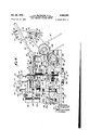
- Fig. 1 is a plan of base ring feeding mechanism, embodying our invention, and part of a basemaking machine, modified to take base rings in accordance with said invention.
- Fig. 2 is a side elevational view of the mechanism, as on the line II-II of Fig. 1, in the direction of the arrows.
- Fig. 3 is a vertical section-a1 view on the line IIIIII of Fig. 1, in the direction of the arrows.
- Fig. 4 is a front elevational view of the mechanism, as on the line IV--IV of Fig.1, in the direction of the arrows.
- Fig. 5 is a horizontal sectional view on the line V--V of Fig. 3 in the direction of the arrows.
- Fig. 6 is a horizontal sectional view on the line VI-VI of Fig. 7, in the direction of the arrows.
- Fig. 7 is a'vertic-al sectional view on the line VIIVIl' of Fig. 6, in the direction of the arrows.
- Fig. 8 is a fragmentary side elevational view on the line VIIIVIII of Fig. 2, in the direction of the arrows.
- Fig. 9 is a fragmentary vertical sectional view on the line IX-IX of Fig. 2, in the direction of the arrows.
- Fig. 10 is a fragmentary vertical sectional view on the line X-X of Fig. 9, in the direction of the arrows.
- Fig. 11 is a vertical sectional view on the line Ifl-XI of Fig. 12, in the direction of the arrows.
- Fig. 12 is a fragmentary horizontal sectional view on the line XIIXII of Fig. 4, in the direcrtion of the arrows.
- Fig. 13 is an exploded view of certain of the parts shown in Figs. 11 and 12.
- Fig. 14 is a vertical sectional view of one of the glass receiving dies and the actuating cams.
- Fig. 15 is a diagrammatic plan of the glass re DCving dies.
- Fig. 16 is a perspective of one of the base rings embodying our invention, as handled by the mechanism.
- Fig. 17 is a lamp including one of the said rings as a part thereof, and
- Fig. 18 is a bottom plan of the base portion of the lamp shown in Fig. 17.
- the mechanism shown in the drawings is de signed for use with a base-making machine of the type described and claimed in the Walker et al. patents, Nos. 1,210,237 and 1,210,238, both dated December 26, 1916.
- a base-making machine makes base-s each with only a first-fed center contact, feeding thereof being specifically claimed in the first of said patents, and a thereafter-fed outer shell, feeding thereof being specifically claimed in the second of said patents
- the illustrated embodiment of the mechanism of the present invention is for feeding a ring or third contact ahead of the placing of the center contact in one die or shell holder after another to make bases, of thte mogul type, with three contacts for the so-called Three-lite lamp, such a lamp being illustrated in Figs. 1'7 and 18.
- the base of said lamp therefore, instead of having only a shell and center contact, has an intermediate ring which is positioned first in each die or shell holder and embedded in the glass insula- 3 tion between the shell and center contact member.
- the ring contact element 32 is shown in perspective in Fig. 16. In the embodiment illustrated, it is desirably cut from sheet brass, or similar material, generally circular in outline with a center opening 34, from th peripheral portion defining which extend tapering, curved a ld' inclined lugs 35 which in the course of manufacture become embedded in the glass insulation 33.
- the ring is also provided with an axiallyoffset apertured or frusto-conical hollow boss. 36 which receives the lead 28 and is soldered 01 otherwise connected thereto.
- the ring is thus of special construction, avoiding sharp angles and pron s which had been used, thereb for the first time makin it suitable for automatic or machine feeding.
- the molten glass which is fed to the base-making machine to form the base insulation 33 desirably passes through a die or guide of durable material, such as described and claimed in the Weller patent, No. 2,031,083 of February 18, 1936, and the Richardson patent, No. 2,190,296 of February 13, 1940, the temperature of the molten glass stream, being desirably controlled in accord ance with the Richardson et al. patent, No. 2,116,450.01: May 3, 1938.
- Feeding rings from hopper to dial Referring in detail to the illustrated embodi.-.
- the slide 3] has a groove M in each side element to receive edge portions of the rings 32, while allowing them to slide freely to the dial 43.
- the rings are fed singly by mechanism associated with the slide 31 to control the number of rings out of the hopper.
- the slide is kept approximately three-quarters full.
- the hopper itself is operated by an electric motor and automatically stops when the slide is filled to the desired extent.
- the mechanism for feeding the rings, down the slide consists of a finger 46 pivoted with respect to the slide 31, as indicated at 47, and normally urged to its lowermost position by means of spring 48 acting between a rearward or upward extension 49 of said finger and an abutment on the slide 31.
- This finger therefore, prevents rings from moving therebeyond until a ring is, forcibly moved past it.
- is provided for feeding rings past the finger 46.
- is rotatabl mounted on abolt 52 carried by. a rotatable member 53, including a shaft 54 journalled in and supported by bracket 55; depending from the slide 31.
- Shaft 54' carries a sprocket wheelfifi driven by a chain 51 from a sprocket wheel 58; on the left hand; drive shaft 59of the machine.
- This shaft 59- is in turndriven from the same source of power which operates the shell hopper of the base machine, thussynchronizing the ring feed with that of the shells and eyelets to the base machine.
- FIG. 1- A consideration ofFig. 1- will show that the upper flanges defining grooves 44. are cut away to provide an opening 50;. The purpose of this is to permit the rings to be removed at this point in case of a jam in the slide or at the dial. If in so doing the dial indexes without all of the pockets 45 thereof filled, the operator has time to load the dial by hand. This-is one of the reasons for the relatively large movement of the dial between the ring-feed; position and the point Where the rings are pushed therefrom to the transfer fingers.
- the finger fil rotates counterclockwise, as indicated by the arrow in Fig. 4, periodicall y engages the ring- 32- which'is then held, b the finger 46, and moves it free thereof against the resistance of the spring 48 -to,allow itto slide to position in the indexed, pocket 45. of the dial 43, as shown most clearly in Fig, 1. If someobstruction prevents freerelease of the ring from the fin er t6, breaka e of the mechanism is r t v ntr ed by the finger 5
- dial 43 Operation of dial
- the dial 43 is secured to rotatably-mounted drive shaft II which carries a ratchet 12, in turn driven by an indexing pawl I3 resiliently urged into engagement therewith by spring M which acts between it and plate I5, to which said pawl is connected as by means of pivot member I6 (Fig. 5).
- the plate I5, which has a running fit on the shaft 'II, is oscillated to cause the pawl I3 to drive the ratchet I2 and its connected dial, as by means of a cam '11 on the drive shaft 59 engaging a roller 18 on an operating lever 19 pivoted to the frame of the machine, as indicated at 8
- a spring 83 acts on the pawl plate to urge it clockwise and thereby maintain engagement between the roller I8 and the cam 11.
- the ratchet 12 has teeth corresponding numerically with the ring dial pockets 45, in this instance twenty, so that each ratchet operation advances the ring dial one pocket.
- Braking or friction-drag means are desirably associated with the drive shaft 59 in order to prevent overrunning during operation.
- Such means in the present embodiment takes the form of brass blocks 80 and 90 frictionally engaging the preferably steel shaft II (Fig. 9).
- the block 80 is desirably pivotally secured to the base plate of the frame I00, as by means of a pin or bolt I20, and the block 90 is urged by coil spring I to hold both resiliently against the shaft.
- the spring I40 is mounted on a bolt I the head of which is notched for adjustment by means of screw driver. The bolt passes loosely through the block 90, is threaded to the block 80, and the other end is engaged by a lock nut I60 pressing against the outer face of the block 80.
- the vertical movement is effected by a cam 81 on the rear cam shaft 88, which shaft is driven from the drive shaft 59 through bevel gears 89 and 9I.
- the cam 81 effects the desired vertical reciprocatory movement of the plunger 84 by engaging a roller 92 on cam lever 93, held in engagement with said cam by means of spring 94, and slidable on lever 95 which imparts horizontal motion to the plunger slide 96, as by having a slot 91 receiving bolts 98 and 99 projecting laterally from the lever 95.
- the bolt 99 also serves to pivot the lever 95 to the frame I00 of the machine (Fig. 3) and the spring 94 acts between the bolt 99 and the pivot member II 0 connecting the lever 93 to its link IOI.
- Motion is transmitted from the cam lever 93 throu h link IOI, adjustable link I02, plunger raising link I93, the last of which is pivoted to plunger bearing bracket I04, as indicated at I05.
- the link IOI is slidably pivoted on the link I06 which connects the lever 95 with the plunger slide 96, as by being slotted, as indicated at I87, to receive a pivot member I08 on said link I06. It will, therefore, be seen that rotation of the rear cam shaft 88 effects vertical movement of the plunger 84 through the cam 81.
- Horizontal movement of the plunger 84 is effected by means of cam I09 acting on roller III carried by cam lever II2 fixed on a pivotally mounted shaft I80, controlled by return spring Hi, and connected by link II3 to lever 95 by means of bolt 98.
- Action of the spring IIl is augmented by coil spring I82 acting on the free end of crank I fixed on' shaft I60.
- the lever acts on plunger bearing bracket I04 through link I06 and plunger slide 96, the latter of which moves in plunger slide block II4 carrying an adjustable stop II5 for the plunger bearing bracket I04.
- cams H9 and IZI operate together as a single box cam by respectively engaging rollers I25 and I26, both on lever I21, pivoted to the frame at I28, to cause said lever to operate the transfer finger slide I29 through link block I30 bolted thereto, back and forth between the position shown in Figs. 6 and '7 and that shown in Figs. 2 and 3, by means of adjustable resilient linkage device I3I, whereby a ring engaged between the fingers 86 is moved forward to a position directly over the turning head I I8.
- the resilient linkage device as shown most clearly in Fig. '7, comprises a housing member I32 in which operates plunger I33 controlled by spring I34.
- the 'free or outer end of the plunger I33 is adjustably connected to a threaded socket member I35 and locked in adjusted position by nuts I36.
- the housing member I32 around the plunger I33 is closed by means of a bushing I31 in which the plunger may reciprocate.
- Reciprocatory movement of the block I30 is controlled by a stop rod I38 pivoted to th member I39, which also connects the socket member I35 to said block.
- the rod I38 slides in the upstanding portion I4I of the angular stop device I42 secured to the frame of the machine.
- the extreme outer fingers I45 being likewise pivoted to the same slide I29 by means of bolts I46. These fingers I45 are for the purpose of gripping a ring, after being released by the rear fingers and turned to the proper position, for inserting in the, glass machine.
- FIG. 3 shows the shaft I56 in its uppermost position, downward movement of said shaft being limited by the stop member I63.
- the movement of the head II8 to turn a, supported ring to the proper position for feeding to the glass machine, while said head is in elevated position as shown in Fig. 3, is effected by means of cooperating cams I 64 and I 65, the former of which is fixed to the drive shaft 59 andthe latter to the driv shaft I66.
- Shaft I66 is driven from the shaft 88 by bevel gears I61 and I68.
- the cams I64 and I65 respectively engage rollers I69 and IN on turning head cam slide I12 which reciprocates in its slide block I13, as shown most clearly in Figs. 11, 12 and 13.
- the slide I12 actuates a gear segment I14 connected to the block I13 by pivot member I15, and
- the head I I8 has a cavity I83, closed by a bushing I84 which is secured thereto by set screw I85, containing a spring I86 adjustable in compression by means of set screw I81, and operating a positioning pin I88 to urge it into uppermost position, which position it attains after the head I I8 engages a ring 32 and sufficient rotation has occurred to cause it to register with and pass through the apertured ring boss 36.
- the free end of the lever I99 overlies an actuating pin 202, underlies a shoulder 203, and fits between bifurcated portions 204 of an actuating link 205.
- the upper portion of the link is reduced in section, as indicated at 206, to pass through the supporting post I93 and has a link connector 201 secured to its upper end portion, as by means of a set screw 2 I0.
- the connector 201 is, slidably pivoted to the adjacent bifurcated end portion of the link 208 by means of a pin 209.
- the link portion 206 carries a coil spring 2I I, part of which is housed in the post I93, as shown most clearly in Fig. 9, and the upper end of which engages the connector 201.
- The. link 208 is connected to a standard 2I2, supported from the fram of the machine by a. nut 2I3 and frame bracket 2I4 by means of a pivot pin M5, the other similarly bifurcated end of said link 206 being slidably pivoted to the clevis 2I6 by means of a pin 2I1.
- the upper portion of said clevis is bifurcated to receive the end portion of the link 2538.
- he upper end of the plunger I 89 is adjustably connected to the yoke 2I6 by threadable engagement, indicated at 2I8, as shown in Fig. 3, and tightened by a screw 22I.
- the placer plunger 224 is carried by a holder 225 which is supported between flanges'226 and 221 to the holding arm I9I, which, as previously explained, is supported from the reciprocatory block I92.
- the block I92 resiliently urged to its lowermost position by return spring 230, is moved up by cam 228 on shaft I66 engaging roller 229 on lever 23I, the outer end of which lever is connected to the frame by pivot pin 232 and the free end of which is connected to the reciprocatory block I92 by link 233.
- the upper end of the link 233 engages a pivot member 234 projecting from the block I92 and its lower end is pivoted to the lever 23I by bolt 235.
- the base-making machine is diagrammatically represented in Fig. ,15 as having twenty-four heads. After unloading and cleaning each glass die assembly or head 24! at the positions indicated, such a head of the machine has its parts positioned as shown in Figs. 3 and 14 at the time of feeding a ring 32 thereto.
- the spider 242 of the base-making machine 238 has a series of pockets 243 around its periphery for receiving the elements of the base dies or heads.
- These elements for each head comprise an upper outer die housing member 244 secured to the spider 242 in any desired manner, as by means of screws 245, as shown in Fig. 1.
- Inside of this member 244 is a bushing 246, secured in place as by means of a set screw 241.
- Mounted for reciprocation in the bushing 246 is the die proper or base elements support 248, presenting an upwardly opening pocket, the outer portion 249 of which is formed to support a base shell 29, the inner portion 25! of which is shaped to receive a center contact 3!, and the intermediate portion 252 is formed to support a ring 32.
- This die proper has a bottom portion 253 connected to the top or base supporting portion by columns 254 and normally connected to an interior cam-actuated member 255 by means of a set screw 256. Turning of the cam-actuated member 255 and the associated die proper 248 is prevented by pin 251 held in place by set screw 258.
- the member 255 by action of the cam 259, holds the die proper 248 in upper most position, as shown in Fig. 14. After application of the ring 32 and center contact 3
- a plunger member 26! has its stem 262 reciprocatingly mounted with respect to the member 255 and carrying acam-actuated member 263, so that it may be moved from the uppermost position illustrated in Fig. 14 to the lower position (not shown), the push-up cam being designated by the reference character 264.
- the head 265 of the plunger 26! carries a pin 266, receivable in a corresponding aperture in the die proper 248, and which passes through the apertured boss 36 of a ring 32 when the latter is fed thereto, thereby holding said ring in the desired position while the base parts are being filled with molten glass and being retracted by a pull-down cam (not shown), which engages the upper face of the part 263 at the proper time, so as to withdraw the pin 266 from the die proper to form the opening 261 through the glass insulation 33 of the base 30 being formed, to allow for passage [of the lead-in conductor 28, as shown most clearly in Fig. 17,
- a friction collar 269 consisting of a plurality of annular members 21! held together about the stem 262 by a coil spring 212, is provided. Movement of the collar 269 to above the position illustrated in Fig. 14 is prevented by overlying shoulders 213. Turning of the plunger 26! with respect to the cam-actuated member 255 is prevented by engagement between shoulders on the latter and cooperating shoulders on the member 263.
- the cam 259 then allows the die proper 248 and frictionally-held plunger member 26! to descend so that when the die 24! reaches the position designated shell feed, the die proper is at the bottom of its permitted movement, and the bushing 246 and die proper 248 provides a pocket with walls of substantial height for holding the shell 29 in place during the time the molten glass is fed thereto in the position designated glass feed, also as in accordance with said Walker et al. patents.
- the method of feeding contact rings comprising placing them one by one in pockets of an intermittently rotating dial, removing said rings one by one from said dial ata different place along its periphery, turning said rings one by one until lead-in-conductor-receiving apertures th-ereoi are properly positioned for an associated 11 base-making machine, and then moving said psitioned rings one by one to the lower dies of said base-making machine.
- the method of feeding contact rings comprising placing them one by one in pockets of an intermittently rotating dial, removing said rings one by one from said dial pockets and carrying them radially along a slide, picking up said rings one by one and advancing them still further, turning said rings so that they are properly disposed for insertion in an associated base-making machine, and moving said rings until they one by one are positioned directly over a die of said base-making machine.
- the method of feeding contact rings comprising moving them one by one in to a dial, intermittently rotating said dial so that peripheral pockets thereof sequentially receive one ring from said hopper, removing said rings one by one from said dial pockets and carrying them radially along a slide, picking up said rings one by one and advancing them still further, turning said rings about their axes 'so that they are properly disposed for insertion in an associated basemaking machine, moving said rings until they one by one are positioned directly over a die of said base-making machine, and then feeding each sequentially downwardly into the die which then registers therewith.
- the method of making bases for electric lamps comprising feeding a contact ring, which has a single offset aperture for a lead-in conductor, into a pocket of an intermittently rotating dial, removing said ring from said dial, turning said ring until its offset aperture is positioned above and in alignment with a plunger pin of an associated base-making machine, placing said ring in a lower die of said machine, with said pin carried by a die-associated plunger fitting said offset aperture, when the bottom portion of said die and its plunger are in raised position, placing a, base eyelet in said die, lowering the bottom portion of said die, placing a base shell therein, feeding molten glass to said die to consolidate the shell, ring and eyelet, forming the glass in said die, and lowering the associated pin plunger to remove its pin from the conductor aperture of said ring.
- Apparatus for feeding rings comprising means for feeding rings one by one, a dial rotatable about a vertical axis and provided with a plurality of pockets, each of which is adapted to receive one ring, means for rotating said dial so that one pocket after another is brought to register with and receive a ring from the feeding means a plunger slide mounted to move hori- -zontally over said dial, a plunger mounted for vertical reciprocation in said slide, means for operating said plunger, and means for moving 12 holding pockets one after another register therebeneath, said plunger moves downward, engages a ring, and slides it radially out of said dial.
- Apparatus for feeding rings comprising means for feeding rings one by one, a dial rotatable about a vertical axis and provided with a plurality of pockets, each of which is adapted to receive one ring, means for rotating said dial so that one pocket after another is brought to register with and receive a ring from the feeding means, a plunger associated with said dial, means for operating said plunger whereby as the ringholding pockets one after another register therebeneath, said plunger moves downward, engages a ring, and slides it radially out of said dial, a plate carrying front and rear sets of fingers, means for causing said plate to reciprocate whereby said rear fingers grasp a ring as it is released by said plunger and move it forward to a desired position, a head having a spring-actuated positioning pin projecting upwardly therefrom, means for raising said head and simultaneously rotating the same beneath the ring held by said fingers, and a holding plunger depressible to maintain said ring in engagement with said head, for turning the ring to a desired
- Apparatus for feeding rings comprising means for feeding rings one by one, a dial rotatable about a vertical axis and provided with a plurality of pockets, each of which is adapted to receive one ring, means for rotating said dial so that one pocket after another is brought to register with and receive a ring from the feeding means, a plunger associated with said dial, means for operating said plunger, whereby as the ringholding pockets one after another register there-' beneath, said plunger moves downward, engages a ring, and slides it radially out of said dial, a plate carrying front and rear sets of fingers, means for causing said plate to reciprocate whereby said rear fingers grasp a ring as it is released by said plunger and move it forward to a desired position, a head having a spring-actuated positioning pin projecting upwardly therefrom, means for raising said head and simultaneously rotating the same beneath the ring held by said fingers, a holding plunger depressible to maintain said ring in engagement with said head, for turning the ring to the desired position, means for
- Apparatus for feeding rings comprising means for feeding rings one by one, a dial rotatable about a vertical axis and provided with a plurality of pockets, each of which is adapted to receive one ring, means for rotating said dial so that one pocket after another is brought to register with and receive a ring from the feeding means, a plunger associated with said dial, means foroperating said plunger, whereby as the ringholding pockets one after another register therebeneath, said plunger moves downward, engages a ring, and slides it radially out of said dial, a
- a machine has a series of movable dies with vertically reciprocable bottomv portions for supporting the baseelements and receiving molten glass for consolidating said elements, means for feeding an eyelet to each die, means for lowering the bottom portion of each die, and means for then feeding a base shell thereto, the combination therewith of a single plunger pin cooperating with each bottom die portion for making a lead-receiving hole in the contact ring portion of each base being formed, means for feeding, one by one, base contact rings, each of which has a single aperture in its peripheral portion for receiving a lead wire, means for turning each ring about its axis to a position so that its aperture will register with said plunger pin when it is placed in one of said dies,.
- each ring means for moving each ring until it overlies a die and then releasing it to drop in place therein, with said pin received in its lead aperture, prior to the feeding of the eyelet and base shell thereto, means for feeding mol en glass to said die after the feeding of said eyelet and base shell, to consolidate said ring, eyelet and shell, and means for shaping said glass and withdrawing said pin to leave a hole therein for a lead connection to said ring.
- the method of making bases for electric lamps comprising moving a contact ring, which has a single offset aperture for a lead-in conductor, along a predetermined path, turning said ring until its offset aperture is positioned above and in alignment with a plunger pin of an associated base-making machine, and then dropping said ring into a lower die of said machine, with said pin, carried by a die-associated plunwith said pin, carried by a die-associated plunger, received in the offset aperture of said ring.
- the method of making bases for electric lamps comprising moving a contact ring, which has a single offset aperture for a lead-in conductor, along a predetermined path, turning said ring until its offset aperture is positioned above and in alignment with a plunger pin of an associated base-making machine, placing said ring in a lower die of said machine, with said pin carried by a die-associated plunger fitting the offset aperture of said ring, the bottom portion of said die and its plunger being in raised position, placing a center contact in said die, lowering the bottom portion of said die, placing a base shell therein, feeding molten glass to said die to consolidate the shell, ring and center contact, forming the glass in said die, and lowering the associated pin plunger to remove its pin from the offset aperture of said ring.
- Apparatus for feeding rings comprising a plate carrying front and rear sets of fingers, means for causing said plate to reciprocate, grasp a ring between its rear fingers and move it forward to a desired position, a head having a springactuated positioning pin projecting upwardly therefrom, means for raising said head and simultaneously rotating the same beneath the ring held by said fingers, and a holding plunger depressible to maintain said ring in engagement with said head for turning the ring to a desired position.
- Apparatus for feeding rings comprising means for feeding rings one by one, a dial rotatable about a vertical axis and provided with a plurality of pockets each of which is adapted to receive one ring, means for rotating said dial so that one pocket after another is brought to register with and receive a ring from the feeding means, a plunger associated with said dial, means for operating said plunger whereby as the ringholding pockets one after another register therebeneath', said plunger moves downward, engages a ring, and slides it radially out of said dial, a plate carrying fingers, and means for causing said plate to reciprocate, grasp a ring as it is released from said plunger and move it forward.
- Apparatus for feeding rings comprising a, plate carrying front and rear sets of fingers, means for causing said plate to reciprocate, grasp a ring between its rear fingers, and move it forward to a desired position, a head having a springactuated positioning pin projecting upwardly therefrom, means for raising said head and simultaneously rotating the same beneath the ring held by said fingers, a holding plunger depressible to maintain said ring in engagement with said head for turning the ring to a desired position, means for retracting said finger-carrying plate to cause the front fingers to grasp said ring, and means for withdrawing said turning head and plunger and moving said finger-carrying plate to carry said ring forward to another position.
- Apparatus for feeding rings which have apertures for lead-in conductors, comprising a plate carrying front and rear sets of fingers, means for causing said plate to reciprocate, grip a ring between its rear set of fingers and move it forward to a desired position, a head having a spring-actuated positioning pin projecting upwardly therefrom, means for raising said head and simultaneously rotating the same beneath the ring held by said fingers, so that said pin engages the ring in its lead-in conductor aperture and turns it to a desired position, a holding plunger depressible to maintain said ring in engagement with said head for said turning operation, means for retracting said finger-carrying plate to cause the front fingers to grip said ring, means for Withdrawing said turning head and plunger, means for moving said finger-carrying plate forward to move said ring to another position, a placer plunger aligned with the last mentioned position of the ring, and means to cause said placer plunger to descend in registry with the ring, separate the front fingers, and release said ring.
Landscapes
- Engineering & Computer Science (AREA)
- Manufacturing & Machinery (AREA)
- Processing And Handling Of Plastics And Other Materials For Molding In General (AREA)
Description
Oct. 25, 1949. J. B. WHITMORE ET AL v2,486,085
METHOD AND MACHINE FOR FEEDING RING CONTACTS IN BASE MAKING Filed Aug. 26', 1942 9 Sheets-Sheet 1 l I 'l mam g ATTORNEY 0st. 25, 1949. J B. WHITMORE ET AL 2,435,085
METHOD AND MACHINE FOR FEEDING RING CONTACTS IN BASE MAKING Filed Aug. 26, 1942 9 Sheets-She et 2 p. Nay/7MP WWW}, v ATTORNEY mm S Q a INVENTOR5 z m r w a w Oct. 25,1949.-
Filed Aug. 26. 1942 J. B. WHITMORE ETAL METHOD AND MACHINE FOR FEEDING RING CONTACTS IN BASE MAKING 9 Sheets-Sheet 3 -INVENTOR$ JTJJW/II-Ma/PA- L u Mam/4D BY N ATTORNEY Oct. 25, 1949. J B WHITMORE ETAL ,0
METHOD AND MACHINE FOR FEEDING RING CONTACTS IN BASE MAKING 9 Sheets-Sheet 4 Filed Aug. 26, 1942 Q a: m .w% 5 mm L MN ma m Q M..- i
Oct. 25, 1949. A J. B. WHITMORE ET AL 2,486,035
METHOD AND MACHINE FOR FEEDING RING CONTACTS I 'N BASE MAKING Filed Aug. 26, 1942 9 Sheets-Sheet 5 INVENTORS 4.0. Mot/9N2 .BY
-. ATTORNEY J? a. WHITMJZE v Oct. 25, 1949. J. B. WHITMORE ET AL METHOD AND MACHINE FOR FEEDING RING CONTACTS IN BASE MAKING 9 Sheets-Sheet e Filed Aug. 26. 1942 PW H i 1 o o Ini 5 =I Q a u {El g u I: o o
BY- .D.
WWW/1 I ATTORNEY 9- J. B. WHITMORE ET AL 2,486,085
7 METHOD AND MACHINE FOR FEEDING I RING CONTACTS IN BASE MAKING FllBd Aug. 26, 1942 9 Sheets-Sheet 7 Oct. 25, 1949. J. B. WHITMORE ETAL 2,436,085
METHOD AND MACHINE FOR FEEDING RING CONTACTS IN BASE MAKING 9 Sheets-Sheet 8 Filed Aug. 26. 1942 INVENTORS 77.3. WH/FMOKE ATTORNEY Oct. 25, 1949. J. B. WHITMORE ET AL METHOD AND MACHINE FOR FEEDING RING CONTACTS IN BASE MAKING 9 Sheets-Sheet 9 Filed Aug. 26, 1942 J M a M :NvENToRs I .3. 1401/7740?! 4 .p. Maze/9N0 21/8 i wg 4 ATTORNEY Patented Oct. 25 1949 UNETED STATES PATENT OFFICE METHOD AND MACHINE FOR FEEDING RING CONTACTS IN BASE MAKING Application August 26, 1942, Serial No. 456,200
20 Claims. (Cl. 49-2) This invention relates to base making and, more particularly, to a method and machine for feeding a contact ring to a base-making machine.
The principal objects of our invention, generally considered, are to provide a method and machine for effecting the ring feeding operation.
A further object of our invention is the provision of a method for feeding rings to a glass base machine, whereby the same are accurately positioned in the dies thereof, after being turned so that the side aperture is disposed in the proper position for aligning with a positioning pin which maintains an aperture through the glass insulation for receiving a lead-in conductor to connect therewith.
A still further object of our invention is the provision of a machine for feeding rings to a base-making machine, so that said rings are properl positioned in the dies of said machine and in the proper time relation with respect to the positioning of the base shells and center contacts, said machine involving means for feeding the rings one by one to a special dial having a series of pockets or slots around its peripheral portion, each large enough to hold just one ring, said rings being carried by said dial to a selected position, means being provided to engage and move said rings, one at :a time, out Of the dial and along a slide on which each ring is in turn grasped by rear transfer fingers, carried to a turning head, turned while held down by a plunger so that said rings are properly positioned with respect to the base-making machine, moved forward by front transfer fingers, and then engaged by a placer plunger which releases said fingers and drops the rings in desired positions in the base-making machine.
Other objects and advantages of the invention, relating to the particular arrangement and construction of the various parts, will become apparent as the description proceeds.
Referring to the drawings:
Fig. 1 is a plan of base ring feeding mechanism, embodying our invention, and part of a basemaking machine, modified to take base rings in accordance with said invention.
Fig. 2 is a side elevational view of the mechanism, as on the line II-II of Fig. 1, in the direction of the arrows.
Fig. 3 is a vertical section-a1 view on the line IIIIII of Fig. 1, in the direction of the arrows.
Fig. 4 is a front elevational view of the mechanism, as on the line IV--IV of Fig.1, in the direction of the arrows.
Fig. 5 is a horizontal sectional view on the line V--V of Fig. 3 in the direction of the arrows.
Fig. 6 is a horizontal sectional view on the line VI-VI of Fig. 7, in the direction of the arrows.
Fig. 7 is a'vertic-al sectional view on the line VIIVIl' of Fig. 6, in the direction of the arrows.
Fig. 8 is a fragmentary side elevational view on the line VIIIVIII of Fig. 2, in the direction of the arrows.
Fig. 9 is a fragmentary vertical sectional view on the line IX-IX of Fig. 2, in the direction of the arrows.
Fig. 10 is a fragmentary vertical sectional view on the line X-X of Fig. 9, in the direction of the arrows.
Fig. 11 is a vertical sectional view on the line Ifl-XI of Fig. 12, in the direction of the arrows.
Fig. 12 is a fragmentary horizontal sectional view on the line XIIXII of Fig. 4, in the direcrtion of the arrows.
Fig. 13 is an exploded view of certain of the parts shown in Figs. 11 and 12.
Fig. 14 is a vertical sectional view of one of the glass receiving dies and the actuating cams.
Fig. 15 is a diagrammatic plan of the glass re ceiving dies.
Fig. 16 is a perspective of one of the base rings embodying our invention, as handled by the mechanism.
Fig. 17 is a lamp including one of the said rings as a part thereof, and
Fig. 18 is a bottom plan of the base portion of the lamp shown in Fig. 17.
The mechanism shown in the drawings is de signed for use with a base-making machine of the type described and claimed in the Walker et al. patents, Nos. 1,210,237 and 1,210,238, both dated December 26, 1916. Such a machine makes base-s each with only a first-fed center contact, feeding thereof being specifically claimed in the first of said patents, and a thereafter-fed outer shell, feeding thereof being specifically claimed in the second of said patents, Whereas the illustrated embodiment of the mechanism of the present invention is for feeding a ring or third contact ahead of the placing of the center contact in one die or shell holder after another to make bases, of thte mogul type, with three contacts for the so-called Three-lite lamp, such a lamp being illustrated in Figs. 1'7 and 18. The base of said lamp, therefore, instead of having only a shell and center contact, has an intermediate ring which is positioned first in each die or shell holder and embedded in the glass insula- 3 tion between the shell and center contact member.
In Figs. 17 and 18 we have designated the lamp shown by the reference character 2|, as comprising a bulb Z2 and a mount 23 including the filaments 24 and 25 which may be energized separately or together by means of the lead-in conductors 26, 2'! and 28, the ends of which respectively connect with the shell 29 of the base 30, the center contact 3|, and the ring 32, said elements being held together by glass insulation 33 formed therearound.
The ring contact element 32 is shown in perspective in Fig. 16. In the embodiment illustrated, it is desirably cut from sheet brass, or similar material, generally circular in outline with a center opening 34, from th peripheral portion defining which extend tapering, curved a ld' inclined lugs 35 which in the course of manufacture become embedded in the glass insulation 33. The ring is also provided with an axiallyoffset apertured or frusto-conical hollow boss. 36 which receives the lead 28 and is soldered 01 otherwise connected thereto. The ring is thus of special construction, avoiding sharp angles and pron s which had been used, thereb for the first time makin it suitable for automatic or machine feeding.
The molten glass which is fed to the base-making machine to form the base insulation 33, desirably passes through a die or guide of durable material, such as described and claimed in the Weller patent, No. 2,031,083 of February 18, 1936, and the Richardson patent, No. 2,190,296 of February 13, 1940, the temperature of the molten glass stream, being desirably controlled in accord ance with the Richardson et al. patent, No. 2,116,450.01: May 3, 1938.
Briefly, the operations of the machine for feeding rings 32 to the shell supports or bottom glass dies (it being understood that the Walker et a1, patents, previously mentioned, disclose how center contact and shells of bases are thereafter fed to such a machine), are that (1) said specially constructed rings pass from a hopper to a slide, along which they are fed singly by a finger, onto a special dialhaving a series of pockets or slots around its peripheral portion, each of whichis justlarge enough to hold one ring. (2) The rings are preferably carried by the dial three-quarters of a revolution to a, selected position where. (3) each is, in turn, engaged and pushed by a plun er out of its pocket in the dial and along a ring slide on which it is, in, turn, grasped by rear transfer fingers. (4) These fingers carry each ring to (5) a turning head which rises, a holding plunger comes down, the head rotates, anda cating pin enters the lead wire boss and turns the ring about its axis to the position it is to occupy in the bottom die of the base-making machine, Where the lead-receiving aperture in its periph- I move by gravity from the hopper to the ring dial eral portion receives a plunger pin for forming a er comesdown and pushes the ring from the fine.
gers into said die without altering the subsequent eyelet or shell feed.
(1) Feeding rings from hopper to dial Referring in detail to the illustrated embodi.-.
ment of the apparatus or machine portion of our 43. The slide 3] has a groove M in each side element to receive edge portions of the rings 32, while allowing them to slide freely to the dial 43.
The rings are fed singly by mechanism associated with the slide 31 to control the number of rings out of the hopper. The slide is kept approximately three-quarters full. The hopper itself is operated by an electric motor and automatically stops when the slide is filled to the desired extent.
After the rings are loaded into the slide they are discharged at the bottom end; one at a time, onto th dial 63 as said dial indexes, so that each pocket 45 of the dial receives one ring. This permits the rin s to be divided and accurately positioned, as is desirable for the next operation,
The mechanism for feeding the rings, down the slide consists of a finger 46 pivoted with respect to the slide 31, as indicated at 47, and normally urged to its lowermost position by means of spring 48 acting between a rearward or upward extension 49 of said finger and an abutment on the slide 31. This finger, therefore, prevents rings from moving therebeyond until a ring is, forcibly moved past it.
A rotatin finger 5| is provided for feeding rings past the finger 46. This finger 5| is rotatabl mounted on abolt 52 carried by. a rotatable member 53, including a shaft 54 journalled in and supported by bracket 55; depending from the slide 31. Shaft 54'carries a sprocket wheelfifi driven by a chain 51 from a sprocket wheel 58; on the left hand; drive shaft 59of the machine. This shaft 59-is in turndriven from the same source of power which operates the shell hopper of the base machine, thussynchronizing the ring feed with that of the shells and eyelets to the base machine. The drive for the shaft 501s through chain 6|, sprocket wheel 62, gear 63; carried by the same shaft as sprocket wheel 62, idler 64, and gear 65 on shaft 59.
A consideration ofFig. 1- will show that the upper flanges defining grooves 44. are cut away to provide an opening 50;. The purpose of this is to permit the rings to be removed at this point in case of a jam in the slide or at the dial. If in so doing the dial indexes without all of the pockets 45 thereof filled, the operator has time to load the dial by hand. This-is one of the reasons for the relatively large movement of the dial between the ring-feed; position and the point Where the rings are pushed therefrom to the transfer fingers.
By virtue of, the drive mechanism thus de-. scribed, the finger fil rotates counterclockwise, as indicated by the arrow in Fig. 4, periodicall y engages the ring- 32- which'is then held, b the finger 46, and moves it free thereof against the resistance of the spring 48 -to,allow itto slide to position in the indexed, pocket 45. of the dial 43, as shown most clearly in Fig, 1. If someobstruction prevents freerelease of the ring from the fin er t6, breaka e of the mechanism is r t v ntr ed by the finger 5| being resiliently held in the position shown in Fig. 4 by the spring 66 acting between a projection 61 from said finger and a connecting member 58 on the rotating member 53, whereby it normally holds the finger 5I in the position illustrated against the abutment member 69, but allows it to rotate clockwise therefrom if necessary.
(2) Operation of dial The dial 43 is secured to rotatably-mounted drive shaft II which carries a ratchet 12, in turn driven by an indexing pawl I3 resiliently urged into engagement therewith by spring M which acts between it and plate I5, to which said pawl is connected as by means of pivot member I6 (Fig. 5). The plate I5, which has a running fit on the shaft 'II, is oscillated to cause the pawl I3 to drive the ratchet I2 and its connected dial, as by means of a cam '11 on the drive shaft 59 engaging a roller 18 on an operating lever 19 pivoted to the frame of the machine, as indicated at 8|, and connected to the pawl plate I5 by means of a link 82. A spring 83 acts on the pawl plate to urge it clockwise and thereby maintain engagement between the roller I8 and the cam 11. The ratchet 12 has teeth corresponding numerically with the ring dial pockets 45, in this instance twenty, so that each ratchet operation advances the ring dial one pocket.
Braking or friction-drag means are desirably associated with the drive shaft 59 in order to prevent overrunning during operation. Such means in the present embodiment takes the form of brass blocks 80 and 90 frictionally engaging the preferably steel shaft II (Fig. 9). The block 80 is desirably pivotally secured to the base plate of the frame I00, as by means of a pin or bolt I20, and the block 90 is urged by coil spring I to hold both resiliently against the shaft. The spring I40 is mounted on a bolt I the head of which is notched for adjustment by means of screw driver. The bolt passes loosely through the block 90, is threaded to the block 80, and the other end is engaged by a lock nut I60 pressing against the outer face of the block 80.
(3) Removal of rings from dial After the dial 43 has been rotated step by step, counterclockwise, to carry the ring in question 270, while prevented from dislodgment by the cylindrical retainer I0, said ring finally reaches a position immediately beneath a plunger 84 which is to act for the purpose of removing the ring from the dial and carrying it to the right, as viewed in Figs. 1, 2, 3, 6 and 7, along the ring slide 85, where it will be engaged by the rear transfer fingers 86. The plunger 84 has a vertical movement and an independently-controlled horizontal movement.
The vertical movement is effected by a cam 81 on the rear cam shaft 88, which shaft is driven from the drive shaft 59 through bevel gears 89 and 9I. The cam 81 effects the desired vertical reciprocatory movement of the plunger 84 by engaging a roller 92 on cam lever 93, held in engagement with said cam by means of spring 94, and slidable on lever 95 which imparts horizontal motion to the plunger slide 96, as by having a slot 91 receiving bolts 98 and 99 projecting laterally from the lever 95. (Fig. 2.) The bolt 99 also serves to pivot the lever 95 to the frame I00 of the machine (Fig. 3) and the spring 94 acts between the bolt 99 and the pivot member II 0 connecting the lever 93 to its link IOI. (Fig. 8.)
Motion is transmitted from the cam lever 93 throu h link IOI, adjustable link I02, plunger raising link I93, the last of which is pivoted to plunger bearing bracket I04, as indicated at I05. The link IOI is slidably pivoted on the link I06 which connects the lever 95 with the plunger slide 96, as by being slotted, as indicated at I87, to receive a pivot member I08 on said link I06. It will, therefore, be seen that rotation of the rear cam shaft 88 effects vertical movement of the plunger 84 through the cam 81.
Horizontal movement of the plunger 84 is effected by means of cam I09 acting on roller III carried by cam lever II2 fixed on a pivotally mounted shaft I80, controlled by return spring Hi, and connected by link II3 to lever 95 by means of bolt 98. (Fig. 3.) Action of the spring IIl is augmented by coil spring I82 acting on the free end of crank I fixed on' shaft I60. The lever acts on plunger bearing bracket I04 through link I06 and plunger slide 96, the latter of which moves in plunger slide block II4 carrying an adjustable stop II5 for the plunger bearing bracket I04.
It will, therefore, be seen that operation of the machine causes the plunger 84 to move into engagement with an indexed ring 32 therebeneath, slide it from a position corresponding with that shown in Figs. 2 and 3, to the right along the ring slide 85, to where it is lodged between the rear transfer fingers 86, which are resiliently held in gripping engagement therewith by means of spring H6, and then return to its starting position.
(4.) Movement of rings by rear transfer fingers to turning head position cams H9 and IZI, respectively mounted on shafts 88 and I22. Shaft I22 is driven from shaft 88 by engagement of a gear I23 fixed on the shaft 88 with one I24 fixed on the shaft I22. (Fig. 5.)
These two cams H9 and IZI operate together as a single box cam by respectively engaging rollers I25 and I26, both on lever I21, pivoted to the frame at I28, to cause said lever to operate the transfer finger slide I29 through link block I30 bolted thereto, back and forth between the position shown in Figs. 6 and '7 and that shown in Figs. 2 and 3, by means of adjustable resilient linkage device I3I, whereby a ring engaged between the fingers 86 is moved forward to a position directly over the turning head I I8.
The resilient linkage device, as shown most clearly in Fig. '7, comprises a housing member I32 in which operates plunger I33 controlled by spring I34. The 'free or outer end of the plunger I33 is adjustably connected to a threaded socket member I35 and locked in adjusted position by nuts I36. The housing member I32 around the plunger I33 is closed by means of a bushing I31 in which the plunger may reciprocate. Reciprocatory movement of the block I30 is controlled by a stop rod I38 pivoted to th member I39, which also connects the socket member I35 to said block. The rod I38 slides in the upstanding portion I4I of the angular stop device I42 secured to the frame of the machine. The extreme outer fingers I45 being likewise pivoted to the same slide I29 by means of bolts I46. These fingers I45 are for the purpose of gripping a ring, after being released by the rear fingers and turned to the proper position, for inserting in the, glass machine.
() Turning of rings Upon movement of a ring to position directly over the turning head I I8, the latter being in depressed position, raising of said head is effected by action of cam I41 on roller I48 of cam lever I49 pivotally mounted on the frame by means of pivot pin I5I to which it is fixed. The other end of the pivot pin I5I has an arm I52 extending therefrom and bifurcated as indicated at I53 to straddle a portion of the turning head shaft I54, at a spool portion I55 between outstanding flanges I56 and I51 thereof, as shown most clearly in Figs. 3 and 4.
Vertical movement is permitted, without dis.- engagement between the pinion I58 on th shaft I54 and. the gear I59 on the turning head intermediate shaft I6I, by making the face of the gear I59 long enough, as shown most clearly in Fig. 3. This Figure 3 shows the shaft I56 in its uppermost position, downward movement of said shaft being limited by the stop member I63.
The movement of the head II8 to turn a, supported ring to the proper position for feeding to the glass machine, while said head is in elevated position as shown in Fig. 3, is effected by means of cooperating cams I 64 and I 65, the former of which is fixed to the drive shaft 59 andthe latter to the driv shaft I66. Shaft I66 is driven from the shaft 88 by bevel gears I61 and I68. The cams I64 and I65 respectively engage rollers I69 and IN on turning head cam slide I12 which reciprocates in its slide block I13, as shown most clearly in Figs. 11, 12 and 13.
The slide I12 actuates a gear segment I14 connected to the block I13 by pivot member I15, and
prevented from undesired removal by cover plate I held thereon by screws I80, by engagement of roller I16, connected thereto by means of pivot member I11, nut I18, and washer I19, in a slotted portion I8I of said segment. Thus reciprocatory movement from side to side of the cam slide I12 causes the gear segment I14 to operate the pinion I58, through the pinion I82 and gear I59 fixed on the shaft "SI and effect the desired rotary movement of the head I I8.
The head I I8 has a cavity I83, closed by a bushing I84 which is secured thereto by set screw I85, containing a spring I86 adjustable in compression by means of set screw I81, and operating a positioning pin I88 to urge it into uppermost position, which position it attains after the head I I8 engages a ring 32 and sufficient rotation has occurred to cause it to register with and pass through the apertured ring boss 36.
From the foregoing it will be seen that upon transfer of the ring 32 to a position above the head II8, said head raises and rotates until the pin I88 engages the apertured boss 36 in said ring and turns the latter to the position in which it is to be fed to the glass machine.
While this turning of the ring takes place, it is held in position and prevented from being thrown out of the machine by means of a ring a reciprocatory block I92 provided with supporting posts I93 and I94, which reciprocate in holding socketed member I95 mounted on the frame of the machine. Movement is effected by cam I91 fixed on shaft I66 and engaging a roller I98 on operating lever I99 pivoted to the frame, as indicated at 20 I.
The free end of the lever I99 overlies an actuating pin 202, underlies a shoulder 203, and fits between bifurcated portions 204 of an actuating link 205. The upper portion of the link is reduced in section, as indicated at 206, to pass through the supporting post I93 and has a link connector 201 secured to its upper end portion, as by means of a set screw 2 I0. The connector 201 is, slidably pivoted to the adjacent bifurcated end portion of the link 208 by means of a pin 209. The link portion 206 carries a coil spring 2I I, part of which is housed in the post I93, as shown most clearly in Fig. 9, and the upper end of which engages the connector 201.
The. link 208 is connected to a standard 2I2, supported from the fram of the machine by a. nut 2I3 and frame bracket 2I4 by means of a pivot pin M5, the other similarly bifurcated end of said link 206 being slidably pivoted to the clevis 2I6 by means of a pin 2I1. The upper portion of said clevis is bifurcated to receive the end portion of the link 2538. he upper end of the plunger I 89 is adjustably connected to the yoke 2I6 by threadable engagement, indicated at 2I8, as shown in Fig. 3, and tightened by a screw 22I.
It will, therefore, be seen that reciprocation of the plunger I89 is effected by action of the cam I91 on the lever. I99, through the rod 206, link 298, and yoke -2I6, either releasing the plunger I69 from the ring 32 or allowing it to be held in engagement therewith by action of the spring 2 for turning to the proper base-machine feeding position.
(6) Placing rings in base machine The head II 8 having stopped, the ring 32 is grasped by the front fingers I45, when the same have been retracted to the position shown in Figs. 6 and 7. These fingers are actuated by springs 222 acting from studs 220 on transfer slide plate I29 to projections 223 on said front fingers. The turning head |I8 thereupon drops and the plunger I89 rises, allowing the released ring to .be transferred by the front fingers I45 upon movement of the same to the position shown in Fig. 2, so that said ring then underlies the placer plunger 229, as shown in Figs. 2 and 3.
The placer plunger 224 is carried by a holder 225 which is supported between flanges'226 and 221 to the holding arm I9I, which, as previously explained, is supported from the reciprocatory block I92. To effect desired movement of the placer plunger 22-4, the block I92, resiliently urged to its lowermost position by return spring 230, is moved up by cam 228 on shaft I66 engaging roller 229 on lever 23I, the outer end of which lever is connected to the frame by pivot pin 232 and the free end of which is connected to the reciprocatory block I92 by link 233. The upper end of the link 233 engages a pivot member 234 projecting from the block I92 and its lower end is pivoted to the lever 23I by bolt 235.
It will, therefore, be seen that after each ring has been moved to position underlying the placer plunger 224, as shown in Figs. 2 and 3, said plunger descends and the bevelled sides 236 thereof engage the correspondingly inclined bosses 231 adjacent the outer ends of the fingers I45, (Fig. 1) forcing said fingers apart and causing them to release the ring and allow the same to drop down into the die 24! of the base-making machine 238 which at the time is indexed with said plunger. The ridges 239 on the plunger 224 pass between the lugs 35 on the ring and prevent turning thereof during its descent until said ring actually passes 011 the lower end of the plunger.
The base-making machine is diagrammatically represented in Fig. ,15 as having twenty-four heads. After unloading and cleaning each glass die assembly or head 24! at the positions indicated, such a head of the machine has its parts positioned as shown in Figs. 3 and 14 at the time of feeding a ring 32 thereto.
The spider 242 of the base-making machine 238 has a series of pockets 243 around its periphery for receiving the elements of the base dies or heads. These elements for each head comprise an upper outer die housing member 244 secured to the spider 242 in any desired manner, as by means of screws 245, as shown in Fig. 1. Inside of this member 244 is a bushing 246, secured in place as by means of a set screw 241. Mounted for reciprocation in the bushing 246 is the die proper or base elements support 248, presenting an upwardly opening pocket, the outer portion 249 of which is formed to support a base shell 29, the inner portion 25! of which is shaped to receive a center contact 3!, and the intermediate portion 252 is formed to support a ring 32.
This die proper has a bottom portion 253 connected to the top or base supporting portion by columns 254 and normally connected to an interior cam-actuated member 255 by means of a set screw 256. Turning of the cam-actuated member 255 and the associated die proper 248 is prevented by pin 251 held in place by set screw 258.
The member 255, by action of the cam 259, holds the die proper 248 in upper most position, as shown in Fig. 14. After application of the ring 32 and center contact 3|, the die proper 248 is lowered for reception of the shell 29, so that during the glass filling operation, the shell 29 is supported within the bushing 246 and housing 244.
In order to prevent a ring 32, after reception by the die 24!, from turing from the proper position for receiving the molten glass, a plunger member 26! has its stem 262 reciprocatingly mounted with respect to the member 255 and carrying acam-actuated member 263, so that it may be moved from the uppermost position illustrated in Fig. 14 to the lower position (not shown), the push-up cam being designated by the reference character 264.
The head 265 of the plunger 26! carries a pin 266, receivable in a corresponding aperture in the die proper 248, and which passes through the apertured boss 36 of a ring 32 when the latter is fed thereto, thereby holding said ring in the desired position while the base parts are being filled with molten glass and being retracted by a pull-down cam (not shown), which engages the upper face of the part 263 at the proper time, so as to withdraw the pin 266 from the die proper to form the opening 261 through the glass insulation 33 of the base 30 being formed, to allow for passage [of the lead-in conductor 28, as shown most clearly in Fig. 17,
In order to prevent undesired movement of the plunger member 26! with respect to the member 255, as because of its stem 262 becoming loose from wear, a friction collar 269, consisting of a plurality of annular members 21! held together about the stem 262 by a coil spring 212, is provided. Movement of the collar 269 to above the position illustrated in Fig. 14 is prevented by overlying shoulders 213. Turning of the plunger 26! with respect to the cam-actuated member 255 is prevented by engagement between shoulders on the latter and cooperating shoulders on the member 263.
It will, therefore, be seen that after a die 24! has been cleaned by air, at which place the cam 259 and the push-up cam 264 operate to move the die proper 248 and the plunger 26! up to the position illustrated in Fig. 14, a ring 32 is fed thereto at the place indicated by ring feed in Fig. 15 when the parts are still positioned as shown in Fig. 14. The cam 264 acts only momentarily, the plunger 26! staying in place by frictional action of the collar 269. The spider 242 then moves on until the die reaches the position designated eyelet feed in Fig. 15, where the eyelet member 3| is positioned, as in accordance with the Walker et al. patents above referred to.
The cam 259 then allows the die proper 248 and frictionally-held plunger member 26! to descend so that when the die 24! reaches the position designated shell feed, the die proper is at the bottom of its permitted movement, and the bushing 246 and die proper 248 provides a pocket with walls of substantial height for holding the shell 29 in place during the time the molten glass is fed thereto in the position designated glass feed, also as in accordance with said Walker et al. patents.
After the shell 29, center contact 3| and rin 32 in the head 24! have received the desired charge of molten'glass and said glass has had time to harden to some extent, said glass is acted upon by one or more upper shaping plungers, designated and 2 in Fig. 15, but not otherwise shown. The plunger 26! and its associated pin 266 is then lowered with respect to the die proper 248 by means of the pull-down cam (not shown) leaving the base aperture 261, and a pin plunger descends at the position indicated in Fig. 15 to form the aperture 214 which receives the lead-in conductor 21 for connection with the center contact 3!. The die 24! is then unloaded and cleaned, and. the operation may be repeated.
From the foregoing, it will be seen that we have devised a machine which acts in synchronization With the base-making machine to accurately place rings, or third contacts of bases to be formed, in one die after another of a base-making machine, the other contacts, that is, the shell and center contact of each base, being placed in accordance with the Walker et a1. patents, 1,210,237 and 1,210,238, previously referred to.
Although a preferred embodiment of our invention has been disclosed, it will be understood that modifications may be made within the spirit and scope of the appended claims.
We claim:
1. The method of feeding contact rings comprising placing them one by one in pockets of an intermittently rotating dial, removing said rings one by one from said dial ata different place along its periphery, turning said rings one by one until lead-in-conductor-receiving apertures th-ereoi are properly positioned for an associated 11 base-making machine, and then moving said psitioned rings one by one to the lower dies of said base-making machine.
2. The method of feeding contact rings which have apertures for lead-in conductors comprising causing them to feed one by one into pockets of an intermittently rotating dial, removing said rings one by one from said dial, after the same has transferred them through a predetermined angle of rotation, turning said rings one by one about their axes until the 'lead-in-conductorreceiving apertures thereof are properly positioned for an associated base-making machine, and then accurately dropping said rings one by one into the lower dies of said base-making machine, in properly timed relation with respect to the placement of center contacts and shells for the bases.
3. The method of feeding contact rings comprising placing them one by one in pockets of an intermittently rotating dial, removing said rings one by one from said dial pockets and carrying them radially along a slide, picking up said rings one by one and advancing them still further, turning said rings so that they are properly disposed for insertion in an associated base-making machine, and moving said rings until they one by one are positioned directly over a die of said base-making machine.
4. The method of feeding contact rings comprising moving them one by one in to a dial, intermittently rotating said dial so that peripheral pockets thereof sequentially receive one ring from said hopper, removing said rings one by one from said dial pockets and carrying them radially along a slide, picking up said rings one by one and advancing them still further, turning said rings about their axes 'so that they are properly disposed for insertion in an associated basemaking machine, moving said rings until they one by one are positioned directly over a die of said base-making machine, and then feeding each sequentially downwardly into the die which then registers therewith.
5. The method of making bases for electric lamps comprising feeding a contact ring, which has a single offset aperture for a lead-in conductor, into a pocket of an intermittently rotating dial, removing said ring from said dial, turning said ring until its offset aperture is positioned above and in alignment with a plunger pin of an associated base-making machine, placing said ring in a lower die of said machine, with said pin carried by a die-associated plunger fitting said offset aperture, when the bottom portion of said die and its plunger are in raised position, placing a, base eyelet in said die, lowering the bottom portion of said die, placing a base shell therein, feeding molten glass to said die to consolidate the shell, ring and eyelet, forming the glass in said die, and lowering the associated pin plunger to remove its pin from the conductor aperture of said ring.
6. Apparatus for feeding rings comprising means for feeding rings one by one, a dial rotatable about a vertical axis and provided with a plurality of pockets, each of which is adapted to receive one ring, means for rotating said dial so that one pocket after another is brought to register with and receive a ring from the feeding means a plunger slide mounted to move hori- -zontally over said dial, a plunger mounted for vertical reciprocation in said slide, means for operating said plunger, and means for moving 12 holding pockets one after another register therebeneath, said plunger moves downward, engages a ring, and slides it radially out of said dial.
'7. Apparatus for feeding rings comprising means for feeding rings one by one, a dial rotatable about a vertical axis and provided with a plurality of pockets, each of which is adapted to receive one ring, means for rotating said dial so that one pocket after another is brought to register with and receive a ring from the feeding means, a plunger associated with said dial, means for operating said plunger whereby as the ringholding pockets one after another register therebeneath, said plunger moves downward, engages a ring, and slides it radially out of said dial, a plate carrying front and rear sets of fingers, means for causing said plate to reciprocate whereby said rear fingers grasp a ring as it is released by said plunger and move it forward to a desired position, a head having a spring-actuated positioning pin projecting upwardly therefrom, means for raising said head and simultaneously rotating the same beneath the ring held by said fingers, and a holding plunger depressible to maintain said ring in engagement with said head, for turning the ring to a desired position.
8. Apparatus for feeding rings comprising means for feeding rings one by one, a dial rotatable about a vertical axis and provided with a plurality of pockets, each of which is adapted to receive one ring, means for rotating said dial so that one pocket after another is brought to register with and receive a ring from the feeding means, a plunger associated with said dial, means for operating said plunger, whereby as the ringholding pockets one after another register there-' beneath, said plunger moves downward, engages a ring, and slides it radially out of said dial, a plate carrying front and rear sets of fingers, means for causing said plate to reciprocate whereby said rear fingers grasp a ring as it is released by said plunger and move it forward to a desired position, a head having a spring-actuated positioning pin projecting upwardly therefrom, means for raising said head and simultaneously rotating the same beneath the ring held by said fingers, a holding plunger depressible to maintain said ring in engagement with said head, for turning the ring to the desired position, means for retracting said finger-carrying plate to cause the front fingers to grasp said ring, and means for withdrawing said turning head and plunger and moving said finger-carrying plate to carry said ring forward to another position.
9. Apparatus for feeding rings comprising means for feeding rings one by one, a dial rotatable about a vertical axis and provided with a plurality of pockets, each of which is adapted to receive one ring, means for rotating said dial so that one pocket after another is brought to register with and receive a ring from the feeding means, a plunger associated with said dial, means foroperating said plunger, whereby as the ringholding pockets one after another register therebeneath, said plunger moves downward, engages a ring, and slides it radially out of said dial, a
plate carrying front and rear sets of fingers,
means for causing said plate to reciprocate whereby said rear fingers grasp a ring as it is released by said plunger and move it forward to a desired position, a head having a spring-actuated positioning pin projecting upwardly therefrom, means for raising said head and simultaneously rotating the same beneath the ring held by said fingers,
said slide over said dial, whereby as the ringa holding Plunger depressible 50 maintain Said ring in engagement with said head, for turning the ring to the desired position, means for retracting said finger-carrying plate to cause the front fingers to grasp said ring, means for withdrawing said turning head and plunger, means for moving said finger-carrying plate forward to move said ring to another position, a placer plunger aligned with the last mentioned position of the ring, and means to cause said placer plunger to descend in registry with the ring, separate the front fingers, and release said ring.
10. Apparatus for placing base contact rings, each of which has an aperture offset from its axis for receiving a lead wire, in a machine for incorporating the same in bases comprising means for feeding said rings one by one, means for grasping each ring and moving it to a location where it is to be turned, means for turning each ring about its axis while in said location to an aperture position desired for placing it in a lower die of said base-making machine, and means for moving each ring after so turning until 'it overlies said die and then releasing it to drop into place therein.
11. Apparatus for placing base contact rings, each of which has an aperture offset from its axis for receiving a lead wire, in a machine for incorporating the same in bases comprising a dial rotatable about a vertical axis and provided with a plurality of peripheral pockets, each of which is to receive one ring, means for feeding said rings one by one to said pockets as they are indexed with respect to said feeding means, means for withdrawing said rings one by one from another position along the periphery of said dial as Said pockets index therewith, means for grasping each ring and moving it to a location where it is to be turned, means for turning each ring while in said location about its axis to an aperture position desired for placing it in a lower die of said base-making machine, and means for moving each ring after so turning until it overlies said die and then releasing it to drop into place therein.
12. In apparatus for making bases for electric lamps wherein a machine has a series of movable dies with vertically reciprocable bottomv portions for supporting the baseelements and receiving molten glass for consolidating said elements, means for feeding an eyelet to each die, means for lowering the bottom portion of each die, and means for then feeding a base shell thereto, the combination therewith of a single plunger pin cooperating with each bottom die portion for making a lead-receiving hole in the contact ring portion of each base being formed, means for feeding, one by one, base contact rings, each of which has a single aperture in its peripheral portion for receiving a lead wire, means for turning each ring about its axis to a position so that its aperture will register with said plunger pin when it is placed in one of said dies,. means for moving each ring until it overlies a die and then releasing it to drop in place therein, with said pin received in its lead aperture, prior to the feeding of the eyelet and base shell thereto, means for feeding mol en glass to said die after the feeding of said eyelet and base shell, to consolidate said ring, eyelet and shell, and means for shaping said glass and withdrawing said pin to leave a hole therein for a lead connection to said ring.
13. The method of making bases for electric lamps comprising moving a contact ring, which has a single offset aperture for a lead-in conductor, along a predetermined path, turning said ring until its offset aperture is positioned above and in alignment with a plunger pin of an associated base-making machine, and then dropping said ring into a lower die of said machine, with said pin, carried by a die-associated plunwith said pin, carried by a die-associated plunger, received in the offset aperture of said ring.
14. The method of making bases for electric lamps comprising moving a contact ring, which has a single offset aperture for a lead-in conductor, along a predetermined path, turning said ring until its offset aperture is positioned above and in alignment with a plunger pin of an associated base-making machine, placing said ring in a lower die of said machine, with said pin carried by a die-associated plunger fitting the offset aperture of said ring, the bottom portion of said die and its plunger being in raised position, placing a center contact in said die, lowering the bottom portion of said die, placing a base shell therein, feeding molten glass to said die to consolidate the shell, ring and center contact, forming the glass in said die, and lowering the associated pin plunger to remove its pin from the offset aperture of said ring.
15. Apparatus for feeding rings comprising a plate carrying front and rear sets of fingers, means for causing said plate to reciprocate, grasp a ring between its rear fingers and move it forward to a desired position, a head having a springactuated positioning pin projecting upwardly therefrom, means for raising said head and simultaneously rotating the same beneath the ring held by said fingers, and a holding plunger depressible to maintain said ring in engagement with said head for turning the ring to a desired position.
16. Apparatus for feeding rings comprising means for feeding rings one by one, a dial rotatable about a vertical axis and provided with a plurality of pockets each of which is adapted to receive one ring, means for rotating said dial so that one pocket after another is brought to register with and receive a ring from the feeding means, a plunger associated with said dial, means for operating said plunger whereby as the ringholding pockets one after another register therebeneath', said plunger moves downward, engages a ring, and slides it radially out of said dial, a plate carrying fingers, and means for causing said plate to reciprocate, grasp a ring as it is released from said plunger and move it forward.
17. Apparatus for feeding rings comprising a, plate carrying front and rear sets of fingers, means for causing said plate to reciprocate, grasp a ring between its rear fingers, and move it forward to a desired position, a head having a springactuated positioning pin projecting upwardly therefrom, means for raising said head and simultaneously rotating the same beneath the ring held by said fingers, a holding plunger depressible to maintain said ring in engagement with said head for turning the ring to a desired position, means for retracting said finger-carrying plate to cause the front fingers to grasp said ring, and means for withdrawing said turning head and plunger and moving said finger-carrying plate to carry said ring forward to another position.
18. Apparatus for feeding rings, which have apertures for lead-in conductors, comprising a plate carrying front and rear sets of fingers, means for causing said plate to reciprocate, grip a ring between its rear set of fingers and move it forward to a desired position, a head having a spring-actuated positioning pin projecting upwardly therefrom, means for raising said head and simultaneously rotating the same beneath the ring held by said fingers, so that said pin engages the ring in its lead-in conductor aperture and turns it to a desired position, a holding plunger depressible to maintain said ring in engagement with said head for said turning operation, means for retracting said finger-carrying plate to cause the front fingers to grip said ring, means for Withdrawing said turning head and plunger, means for moving said finger-carrying plate forward to move said ring to another position, a placer plunger aligned with the last mentioned position of the ring, and means to cause said placer plunger to descend in registry with the ring, separate the front fingers, and release said ring.
19. Apparatus for placing base contact rings, each of which has an aperture offset from its axis for receiving a lead wire, in a machine for incorporating the same in bases comprising means for moving said rings one by one along a predetermined path, means for grasping each ring and moving it to a location where it is to be turned, means for turning each ring while in said location about its axis to an aperture position desired for placing it in a lower die of said base-making machine, and means for moving each ring after so turning until it overlies said die and then re-, leasing it to drop into place therein.
20. In apparatus for making bases for electric lamps, wherein a machine has a series of movable dies for supporting the base elements and receiving molten glass for consolidating said elements,
the combination therewith of a single plunger pin cooperating with each die for making a leadreceiving hole in the contact ring portion of each base being formed, means for feeding, one by one, base contact rings, each of which has a single aperture in its peripheral portion for receiving a lead wire, means for turning each ring about its axis to a position so that its aperture will register with said plunger pin when it is placed in one of said dies, means for moving each ring until it overlies a die and then releasing it to drop in place therein, with said pin received in its lead aperture, means for feeding molten glass to said die, and means for withdrawing said pin to leave a hole therein for a lead connection to said ring.
JAMES B. WI-HTMORE. LOUIS D. MORAND.
REFERENCES CITED Ihe following references are of record in the file of this patent? UNITED STATES PATENTS Number Name Date 1,210,238 Walker et al Dec. 26, 1916 1,227,244 Buhles May 22, 1917 1,536,740 Akeroyd May 5, 1925 1,712,670 Madden May 14, 1929 1,826,505 Conn Oct. 6, 1931 1,990,258 Trutner Feb. 5, 1935 2,120,877 Uber June 14, 1938 2,157,051 Birdseye May 2, 1939
Priority Applications (2)
| Application Number | Priority Date | Filing Date | Title |
|---|---|---|---|
| US456200A US2486085A (en) | 1942-08-26 | 1942-08-26 | Method and machine for feeding ring contacts in base making |
| US95485A US2519328A (en) | 1942-08-26 | 1949-05-14 | Lamp base and ring therefor |
Applications Claiming Priority (1)
| Application Number | Priority Date | Filing Date | Title |
|---|---|---|---|
| US456200A US2486085A (en) | 1942-08-26 | 1942-08-26 | Method and machine for feeding ring contacts in base making |
Publications (1)
| Publication Number | Publication Date |
|---|---|
| US2486085A true US2486085A (en) | 1949-10-25 |
Family
ID=23811866
Family Applications (1)
| Application Number | Title | Priority Date | Filing Date |
|---|---|---|---|
| US456200A Expired - Lifetime US2486085A (en) | 1942-08-26 | 1942-08-26 | Method and machine for feeding ring contacts in base making |
Country Status (1)
| Country | Link |
|---|---|
| US (1) | US2486085A (en) |
Cited By (7)
| Publication number | Priority date | Publication date | Assignee | Title |
|---|---|---|---|---|
| US2830507A (en) * | 1956-10-08 | 1958-04-15 | Ohio Boxboard Co | Carton erecting machine |
| US2889962A (en) * | 1954-04-09 | 1959-06-09 | Corning Glass Works | Article handling |
| US3172149A (en) * | 1961-12-08 | 1965-03-09 | Fahr Ag Maschf | Device for the insertion of metal parts in press molds |
| US3340990A (en) * | 1965-02-12 | 1967-09-12 | Dichter Jakob | Glass tube feeding devices |
| US3432049A (en) * | 1967-02-20 | 1969-03-11 | Elliotts Liverpool Ltd | Apparatus for automatically feeding articles from a store or batch |
| US4139361A (en) * | 1976-08-30 | 1979-02-13 | Vyskumny Ustav Mechanizacie A Automatizacie | Apparatus for glazing bases of electric bulbs |
| US4247244A (en) * | 1978-08-24 | 1981-01-27 | Coyle Terrence W | Transfer mechanism |
Citations (8)
| Publication number | Priority date | Publication date | Assignee | Title |
|---|---|---|---|---|
| US1210238A (en) * | 1911-02-03 | 1916-12-26 | Gen Electric | Feeding mechanism for base-making machines and the like. |
| US1227244A (en) * | 1915-03-10 | 1917-05-22 | Aluminum Seal Company | Closing-machine. |
| US1536740A (en) * | 1919-09-05 | 1925-05-05 | Gen Electric | Feeding mechanism for base-making machines |
| US1712670A (en) * | 1926-05-10 | 1929-05-14 | Westinghouse Lamp Co | Mechanism for conveying and discharging lamp bulbs |
| US1826505A (en) * | 1929-06-15 | 1931-10-06 | Westinghouse Lamp Co | Self adjusting base and bulb holder |
| US1990258A (en) * | 1933-09-21 | 1935-02-05 | Alfred Hofmann & Company | Manufacture of lamp stems |
| US2120877A (en) * | 1937-04-17 | 1938-06-14 | Gen Electric | Basing machine for electric lamps and similar articles |
| US2157051A (en) * | 1937-03-25 | 1939-05-02 | Birdseye Electric Company | Electric lamp |
-
1942
- 1942-08-26 US US456200A patent/US2486085A/en not_active Expired - Lifetime
Patent Citations (8)
| Publication number | Priority date | Publication date | Assignee | Title |
|---|---|---|---|---|
| US1210238A (en) * | 1911-02-03 | 1916-12-26 | Gen Electric | Feeding mechanism for base-making machines and the like. |
| US1227244A (en) * | 1915-03-10 | 1917-05-22 | Aluminum Seal Company | Closing-machine. |
| US1536740A (en) * | 1919-09-05 | 1925-05-05 | Gen Electric | Feeding mechanism for base-making machines |
| US1712670A (en) * | 1926-05-10 | 1929-05-14 | Westinghouse Lamp Co | Mechanism for conveying and discharging lamp bulbs |
| US1826505A (en) * | 1929-06-15 | 1931-10-06 | Westinghouse Lamp Co | Self adjusting base and bulb holder |
| US1990258A (en) * | 1933-09-21 | 1935-02-05 | Alfred Hofmann & Company | Manufacture of lamp stems |
| US2157051A (en) * | 1937-03-25 | 1939-05-02 | Birdseye Electric Company | Electric lamp |
| US2120877A (en) * | 1937-04-17 | 1938-06-14 | Gen Electric | Basing machine for electric lamps and similar articles |
Cited By (7)
| Publication number | Priority date | Publication date | Assignee | Title |
|---|---|---|---|---|
| US2889962A (en) * | 1954-04-09 | 1959-06-09 | Corning Glass Works | Article handling |
| US2830507A (en) * | 1956-10-08 | 1958-04-15 | Ohio Boxboard Co | Carton erecting machine |
| US3172149A (en) * | 1961-12-08 | 1965-03-09 | Fahr Ag Maschf | Device for the insertion of metal parts in press molds |
| US3340990A (en) * | 1965-02-12 | 1967-09-12 | Dichter Jakob | Glass tube feeding devices |
| US3432049A (en) * | 1967-02-20 | 1969-03-11 | Elliotts Liverpool Ltd | Apparatus for automatically feeding articles from a store or batch |
| US4139361A (en) * | 1976-08-30 | 1979-02-13 | Vyskumny Ustav Mechanizacie A Automatizacie | Apparatus for glazing bases of electric bulbs |
| US4247244A (en) * | 1978-08-24 | 1981-01-27 | Coyle Terrence W | Transfer mechanism |
Similar Documents
| Publication | Publication Date | Title |
|---|---|---|
| US2120877A (en) | Basing machine for electric lamps and similar articles | |
| US1941992A (en) | Base feed and staking machine | |
| US2662646A (en) | Device for capping transmitters | |
| US2486085A (en) | Method and machine for feeding ring contacts in base making | |
| US2826003A (en) | Machine for depositing and shaping soil in a transplanting container | |
| GB1233343A (en) | ||
| US2699574A (en) | Moldng machine for molding plastic articles | |
| US2575771A (en) | Mount reshaping apparatus | |
| US2698987A (en) | Machine for assembling parts of lamps preparatory to basing | |
| US2251158A (en) | Transfer and orienting mechanism | |
| US2390121A (en) | Method and machine for assembling washers with screw-threaded fasteners | |
| US3069024A (en) | Machine for looping coil springs | |
| GB2024074A (en) | Apparatus for automatically welding pieces of soldering tape to the contact rings of incandescent lamps | |
| US2519328A (en) | Lamp base and ring therefor | |
| US2515881A (en) | Base shell and feed therefor | |
| US3179319A (en) | Fastener inserting machines | |
| US1760859A (en) | Can-capping machine | |
| US1677133A (en) | Method of and machine for feeding and working articles | |
| US2789585A (en) | Cut-off mechanism for zig zag wire | |
| US1675382A (en) | Battery-making machine | |
| US2762544A (en) | Machine for applying screw closures to collapsible tubes | |
| US1764607A (en) | Screw-threading apparatus | |
| US2197714A (en) | Apparatus for assembling glass applicator rods and bottle caps | |
| US2051035A (en) | Apparatus for closing cartons | |
| US1888429A (en) | Lace tipping machine |