US2483424A - Method of soldering terminals for electrical conductors - Google Patents
Method of soldering terminals for electrical conductors Download PDFInfo
- Publication number
- US2483424A US2483424A US738320A US73832047A US2483424A US 2483424 A US2483424 A US 2483424A US 738320 A US738320 A US 738320A US 73832047 A US73832047 A US 73832047A US 2483424 A US2483424 A US 2483424A
- Authority
- US
- United States
- Prior art keywords
- terminal
- solder
- wire
- terminals
- arms
- Prior art date
- Legal status (The legal status is an assumption and is not a legal conclusion. Google has not performed a legal analysis and makes no representation as to the accuracy of the status listed.)
- Expired - Lifetime
Links
- 238000000034 method Methods 0.000 title description 9
- 239000004020 conductor Substances 0.000 title description 5
- 238000005476 soldering Methods 0.000 title description 5
- 229910000679 solder Inorganic materials 0.000 description 28
- 238000009413 insulation Methods 0.000 description 7
- QTBSBXVTEAMEQO-UHFFFAOYSA-N Acetic acid Chemical compound CC(O)=O QTBSBXVTEAMEQO-UHFFFAOYSA-N 0.000 description 2
- VEXZGXHMUGYJMC-UHFFFAOYSA-N Hydrochloric acid Chemical compound Cl VEXZGXHMUGYJMC-UHFFFAOYSA-N 0.000 description 2
- 230000001680 brushing effect Effects 0.000 description 2
- 238000003780 insertion Methods 0.000 description 2
- 230000037431 insertion Effects 0.000 description 2
- JIAARYAFYJHUJI-UHFFFAOYSA-L zinc dichloride Chemical compound [Cl-].[Cl-].[Zn+2] JIAARYAFYJHUJI-UHFFFAOYSA-L 0.000 description 2
- KWYUFKZDYYNOTN-UHFFFAOYSA-M Potassium hydroxide Chemical compound [OH-].[K+] KWYUFKZDYYNOTN-UHFFFAOYSA-M 0.000 description 1
- 241000220010 Rhode Species 0.000 description 1
- 229920002522 Wood fibre Polymers 0.000 description 1
- 239000003513 alkali Substances 0.000 description 1
- 238000005452 bending Methods 0.000 description 1
- 230000015572 biosynthetic process Effects 0.000 description 1
- 229920002678 cellulose Polymers 0.000 description 1
- 239000001913 cellulose Substances 0.000 description 1
- 238000010276 construction Methods 0.000 description 1
- 230000004907 flux Effects 0.000 description 1
- 239000000463 material Substances 0.000 description 1
- 239000000155 melt Substances 0.000 description 1
- 239000002184 metal Substances 0.000 description 1
- 229910052751 metal Inorganic materials 0.000 description 1
- 230000004048 modification Effects 0.000 description 1
- 238000012986 modification Methods 0.000 description 1
- 229940072033 potash Drugs 0.000 description 1
- BWHMMNNQKKPAPP-UHFFFAOYSA-L potassium carbonate Substances [K+].[K+].[O-]C([O-])=O BWHMMNNQKKPAPP-UHFFFAOYSA-L 0.000 description 1
- 235000015320 potassium carbonate Nutrition 0.000 description 1
- 230000000717 retained effect Effects 0.000 description 1
- 239000002025 wood fiber Substances 0.000 description 1
- 235000005074 zinc chloride Nutrition 0.000 description 1
- 239000011592 zinc chloride Substances 0.000 description 1
Images

Classifications
-
- B—PERFORMING OPERATIONS; TRANSPORTING
- B23—MACHINE TOOLS; METAL-WORKING NOT OTHERWISE PROVIDED FOR
- B23K—SOLDERING OR UNSOLDERING; WELDING; CLADDING OR PLATING BY SOLDERING OR WELDING; CUTTING BY APPLYING HEAT LOCALLY, e.g. FLAME CUTTING; WORKING BY LASER BEAM
- B23K1/00—Soldering, e.g. brazing, or unsoldering
- B23K1/08—Soldering by means of dipping in molten solder
-
- Y—GENERAL TAGGING OF NEW TECHNOLOGICAL DEVELOPMENTS; GENERAL TAGGING OF CROSS-SECTIONAL TECHNOLOGIES SPANNING OVER SEVERAL SECTIONS OF THE IPC; TECHNICAL SUBJECTS COVERED BY FORMER USPC CROSS-REFERENCE ART COLLECTIONS [XRACs] AND DIGESTS
- Y10—TECHNICAL SUBJECTS COVERED BY FORMER USPC
- Y10S—TECHNICAL SUBJECTS COVERED BY FORMER USPC CROSS-REFERENCE ART COLLECTIONS [XRACs] AND DIGESTS
- Y10S206/00—Special receptacle or package
- Y10S206/82—Separable, striplike plural articles
-
- Y—GENERAL TAGGING OF NEW TECHNOLOGICAL DEVELOPMENTS; GENERAL TAGGING OF CROSS-SECTIONAL TECHNOLOGIES SPANNING OVER SEVERAL SECTIONS OF THE IPC; TECHNICAL SUBJECTS COVERED BY FORMER USPC CROSS-REFERENCE ART COLLECTIONS [XRACs] AND DIGESTS
- Y10—TECHNICAL SUBJECTS COVERED BY FORMER USPC
- Y10T—TECHNICAL SUBJECTS COVERED BY FORMER US CLASSIFICATION
- Y10T29/00—Metal working
- Y10T29/49—Method of mechanical manufacture
- Y10T29/49002—Electrical device making
- Y10T29/49117—Conductor or circuit manufacturing
- Y10T29/49204—Contact or terminal manufacturing
- Y10T29/49224—Contact or terminal manufacturing with coating
Definitions
- This invention relates to a wire terminal such as may be attached to an electrical conductor for securing the conductor to some electrical binding post or otherpart. It is desirable in the securing of a terminal to the end of a wire that the terminal be soldered to the wire for a good electrical connection thereto; and, in many instances, it is necessary to apply solder as a separate operation to the wire and the terminal at the time of securing these together. Also, in many instances, the terminals are handled as individual units which is time consuming where large quantities are used.
- One of the objects of this invention is to provide solder assembled with the terminal at a location where the solder is required and in an amount suflicient for securing the terminal to the Wire.
- Another object of this invention is to provide an improved method by which the solder may be easily and .quickly applied and located at the point desired.
- Another object of this invention is to provide a stop for the insertion of an insulated wire so that ⁇ the wire itself will be located Where the solder is provided.
- Another object ofV this invention is the securing of the wire to the terminal and the insulation ⁇ of the wire to the terminal in a manner so that the terminal is well supported on the end oi the wire.
- Another object of this invention is to secure the wire to the terminal by physically clamping the arms oi the terminal on the wire and also by the use of solder.
- Another object of this invention is to form the terminals in a tandem relation and so cut the terminals apart that a burred edge will not occur at the point of severing.
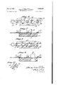
- Fig. 1 is a diagrammatic view illustrating the travel of the terminals in the application of solder thereto;
- Fig. 2 is an enlarged sectional view of one step in the procedure
- Fig. 3 is a perspective view of the strip terminals after having been passed through the various steps shown in Fig. 1;
- Fig. 4 is a top plan view of the wire inserted in the terminal after severed from the strip;
- Fig. 5 is a perspective view of the wire com- 2 pletely attached to the terminal; f
- Fig. '7 is a section of the parts of Fig. 6;
- Figj8 is a View similar to Fig. 6 of a modification
- Fig, 9 is a section of the showing in Fig. 8.
- Fig. 10 is a perspective view of the terminal formed from the strip shown in Figs. 8 and 9.
- this relationship whereby the solder is retained at the locav tion of the bend in the arms is provided, and this bend in the arms also serves the additional useful function of forming a stop to engage the insulation and limit the insertion of the insulated Wire into the terminal to a position desired.
- severing occurs by removing a quantity of stock so as to prevent the burring of the edge of the terminal.
- ID designates generally a strip of terminals which is drawn from a supply package I I of terminals for the application of solder thereto.
- the strip of terminals I0 is formed as an integral strip of tandemly related terminals cut out so that each terminal will have a head portion I2 and a shank portion I3.
- the head portion I2 of one terminal will be joined to the shank portion I3 of the next terminal by means of a short section I4 (see Fig. 6) of sheet stock which Will later be removed.
- Each head will have some opening or recess I5 for securing lt to a binding post.
- Each shank I3 will have a pair of arms I 6 consisting of arms I1 and I8 which will be bent inwardly to overly the shank I3, as shown in Figs. 2 and 3, while there will be a second set of arms
- This tandemly related strip from the package will then be passed through a bath of potash or some other cleaner 22 beneath the guide roll 23 then out over a guide roll 24 and through a bath of acetic or hydrochloric acid 25 beneath the guide roll 26 therein to remove the alkali.
- the strip will then pass over a guide roll 21 and into a bath of flux 28, such as zinc chloride, beneath the guide roll 29 therein and thence over a guide roll 30 and into a hot solder bath 3
- the brushes 33 and 34 will be formed of some rather stiff material, such ⁇ as Wood fiber bristles or cellulose ber bristles to which solder will not adhere.
- the bristles will be conveniently of 1 1/2" long and radially inserted into a drum or hub 3l about in diameter.
- the bristles will be sufcient to form a face about 2 wide. These dimensions, of course, are only illustrative.
- the action of the bristles is such as to wipe from the strip the solder which has accumulated thereon as the strip leaves the solder bath 3
- wire 39 having insulation 4U thereabout is stripped so as to leave a bare portion of the wire extending beyond the part 4
- the arms are bent inwardly to grip the wire and its insulation, heat is applied so that the solder melts and secures the wire to the terminal as shown in Fig. 5, while the arms 9 are bent about and tightly grip the insulation 40 of the wire to hold the Wire firmly secured to the terminal.
- the severing will occur immediately after the soldering operation while the strip of terminals are passing over the bed die 40 which has an opening 4
- This punchor cutter 42 removes the portion 4 of stock which connects the head of one terminal to the shank of the next terminal, and by removing this piece of stock both ends are left square with no burrs upon either edge such as might occur should the stock be sheared without removing a piece.
- a piece designated 45 in the terminals l0 will be removed by a cutter or punch 46 which at the same time removes a sufficient portion so as to leave spacedV arms 41 and 48, as shown in Fig. 10, instead of the circular recess or opening such as I5 in the terminals heretofore spoken of.
- the terminals such as shown in Figs. 6 to 9, will be stored on thereel 36 until ready for use.
- a method ol applying solder to a predetermined area on an element, the steps which comprise immersing an elongated metal article comprising a pluralityl of tandemly ⁇ related elements each of which elements has been provided with upstanding arms overhanging the portion to be coated, in molten solder to encompass the area to be covered and at least a4 portion of the upstanding arms, brushing solder from the elements about and over said arms whereby the upstanding and overhanging arms deiiect the brush bristles from the solder at the desired location beneath said arms to maintain the solder at this location while removing it from the surrounding area.
Landscapes
- Engineering & Computer Science (AREA)
- Mechanical Engineering (AREA)
- Manufacturing Of Electrical Connectors (AREA)
Description
Oct. 4, 1949. R MART|NE5 METHOD OF SOLDERING TERMINALS FOR ELECTRICAL CONDUCTORS Flled March 5l 1947 2 Sheets-Sheet l ATTORN YS.
Oct. 4, 1949. R, MARTlNEs 2,483,424
METHOD 0F SOLDERING TERMINALS FOR ELECTRICAL CONDUCTORS Filed March 31, 1947 2 Sheets-Sheet 2 1N V EN TOR.
Wmv/,0M
ATTORNEYS.
Patented Oct. 4, 1349 METHOD F SOLDERING TERMINALS FOR ELECTRICAL QONDUCTORS Rene Martines, Cranston, R. I., assignor, by mesne assignments, to Electric Terminal Corporation, Providence, R. I., a corporation of Rhode Island Application March 31, 1947, Serial No. 738,320
3 Claims. (Cl. 117-102) This invention relates to a wire terminal such as may be attached to an electrical conductor for securing the conductor to some electrical binding post or otherpart. It is desirable in the securing of a terminal to the end of a wire that the terminal be soldered to the wire for a good electrical connection thereto; and, in many instances, it is necessary to apply solder as a separate operation to the wire and the terminal at the time of securing these together. Also, in many instances, the terminals are handled as individual units which is time consuming where large quantities are used.
One of the objects of this invention is to provide solder assembled with the terminal at a location where the solder is required and in an amount suflicient for securing the terminal to the Wire.
Another object of this invention is to provide an improved method by which the solder may be easily and .quickly applied and located at the point desired.
Another object of this invention is to provide a stop for the insertion of an insulated wire so that` the wire itself will be located Where the solder is provided.
Another object ofV this invention is the securing of the wire to the terminal and the insulation `of the wire to the terminal in a manner so that the terminal is well supported on the end oi the wire. I
Another object of this invention is to secure the wire to the terminal by physically clamping the arms oi the terminal on the wire and also by the use of solder.
Another object of this invention is to form the terminals in a tandem relation and so cut the terminals apart that a burred edge will not occur at the point of severing.
With these and other objects in view, the invention consists of certain novel features of construction as will be more fully described and particularly pointed out in the appended claims.
In the accompanying drawings:
Fig. 1 is a diagrammatic view illustrating the travel of the terminals in the application of solder thereto;
Fig. 2 is an enlarged sectional view of one step in the procedure;
Fig. 3 is a perspective view of the strip terminals after having been passed through the various steps shown in Fig. 1;
Fig. 4 is a top plan view of the wire inserted in the terminal after severed from the strip;
Fig. 5 is a perspective view of the wire com- 2 pletely attached to the terminal; f
as extending across a supporting surface with a punch or kcutter in section for detaehing on terminal from the series;
Fig. '7 is a section of the parts of Fig. 6;
Figj8 is a View similar to Fig. 6 of a modification;
Fig, 9 is a section of the showing in Fig. 8;
Fig. 10 is a perspective view of the terminal formed from the strip shown in Figs. 8 and 9.
In proceeding with the invention, I cut out from sheet stock, by suitable punch and dye operations, a configuration which will lend itself to the formation of terminals in end-to-end relation to be reeled; and, in a second step, I bend the arms from opposite sides of the body so that the arms will be in a form which is desired for the application of solder to the terminals. After this has occurred, the tandemly related terminals will be run through solder and the solder will adhere to the terminals, but will be removed from the terminals at all points except in a location Where a quantity of solder sufficient for attaching a wire to the terminal is desired. By the bending inwardly of certain of the securing arms of the terminal, this relationship whereby the solder is retained at the locav tion of the bend in the arms is provided, and this bend in the arms also serves the additional useful function of forming a stop to engage the insulation and limit the insertion of the insulated Wire into the terminal to a position desired. In the severing of the terminals for after use, severing occurs by removing a quantity of stock so as to prevent the burring of the edge of the terminal.
With reference to the drawings, ID designates generally a strip of terminals which is drawn from a supply package I I of terminals for the application of solder thereto.
The strip of terminals I0 is formed as an integral strip of tandemly related terminals cut out so that each terminal will have a head portion I2 and a shank portion I3. The head portion I2 of one terminal will be joined to the shank portion I3 of the next terminal by means of a short section I4 (see Fig. 6) of sheet stock which Will later be removed. Each head will have some opening or recess I5 for securing lt to a binding post. Each shank I3 will have a pair of arms I 6 consisting of arms I1 and I8 which will be bent inwardly to overly the shank I3, as shown in Figs. 2 and 3, while there will be a second set of arms |9 consisting of arms 20 and 2| which will stand upwardly from the shank in parallel relation leaving an open top, such as shown in Figs. 2 and 3.
This tandemly related strip from the package will then be passed through a bath of potash or some other cleaner 22 beneath the guide roll 23 then out over a guide roll 24 and through a bath of acetic or hydrochloric acid 25 beneath the guide roll 26 therein to remove the alkali. The strip will then pass over a guide roll 21 and into a bath of flux 28, such as zinc chloride, beneath the guide roll 29 therein and thence over a guide roll 30 and into a hot solder bath 3| beneath the guide roll 32; and then as the strip leaves the solder bath, it will pass between brushes 33 and 34 (see also Fig. 2) and thence over a guide` roll 35 and be packaged upon the take-up roll 36.
The brushes 33 and 34 will be formed of some rather stiff material, such` as Wood fiber bristles or cellulose ber bristles to which solder will not adhere. The bristles will be conveniently of 1 1/2" long and radially inserted into a drum or hub 3l about in diameter. The bristles will be sufcient to form a face about 2 wide. These dimensions, of course, are only illustrative. The action of the bristles is such as to wipe from the strip the solder which has accumulated thereon as the strip leaves the solder bath 3|. However, in as much as the arms and I8 of the strip extend inwardly overlying the shank I3, the bristles will be deiiected upwardly, as shown in Fig. 2, at this location, and thus there will occur a globule ofv solder 38 beneath each of these arms which is the location where the solder is desired.
After a terminal is ready for use, wire 39 having insulation 4U thereabout is stripped so as to leave a bare portion of the wire extending beyond the part 4| of the insulation, and this wire is inserted between the arms I9 so that the insulation engages the edge of the arms I6 and the wire extending beneath these arms I5 and on the solder. At the time the arms are bent inwardly to grip the wire and its insulation, heat is applied so that the solder melts and secures the wire to the terminal as shown in Fig. 5, while the arms 9 are bent about and tightly grip the insulation 40 of the wire to hold the Wire firmly secured to the terminal.
Usually a terminal will be attached to a wire prior to its being severed from the strip such as indicated in my copending application Serial No. 611,846, led August 21, 1945, except', of course,
4 the solder is applied as herein above stated rather than as in such prior application.
The severing will occur immediately after the soldering operation while the strip of terminals are passing over the bed die 40 which has an opening 4| therein into which a punch or cutter 42 is received. This punchor cutter 42 removes the portion 4 of stock which connects the head of one terminal to the shank of the next terminal, and by removing this piece of stock both ends are left square with no burrs upon either edge such as might occur should the stock be sheared without removing a piece.
In some cases, instead of removing a piece, such as I4, a piece designated 45 in the terminals l0 will be removed by a cutter or punch 46 which at the same time removes a sufficient portion so as to leave spacedV arms 41 and 48, as shown in Fig. 10, instead of the circular recess or opening such as I5 in the terminals heretofore spoken of. The terminals, such as shown in Figs. 6 to 9, will be stored on thereel 36 until ready for use.
I claim:
1'. In a method ol applying solder to a predetermined area on an element, the steps which comprise immersing an elongated metal article comprising a pluralityl of tandemly` related elements each of which elements has been provided with upstanding arms overhanging the portion to be coated, in molten solder to encompass the area to be covered and at least a4 portion of the upstanding arms, brushing solder from the elements about and over said arms whereby the upstanding and overhanging arms deiiect the brush bristles from the solder at the desired location beneath said arms to maintain the solder at this location while removing it from the surrounding area.
2. In a method as in claim l wherein said brushing is from opposite sides ofA the article.
3. In a method as in claim 1 wherein the element comprises an electrical Wire terminal.
RENE MARTINES.-
REFERENCES CITED The following references are of record in the file of this patent:
UNITED STATES PATENTS- Number Name Date 962,921' Schneider June 28, 1910 1,692,818 Christoph Nov. 27, 1928 1,710,393 Williams April'23, 1929 2,364,904 Keller Dec. 12, 1944
Priority Applications (1)
| Application Number | Priority Date | Filing Date | Title |
|---|---|---|---|
| US738320A US2483424A (en) | 1947-03-31 | 1947-03-31 | Method of soldering terminals for electrical conductors |
Applications Claiming Priority (1)
| Application Number | Priority Date | Filing Date | Title |
|---|---|---|---|
| US738320A US2483424A (en) | 1947-03-31 | 1947-03-31 | Method of soldering terminals for electrical conductors |
Publications (1)
| Publication Number | Publication Date |
|---|---|
| US2483424A true US2483424A (en) | 1949-10-04 |
Family
ID=24967500
Family Applications (1)
| Application Number | Title | Priority Date | Filing Date |
|---|---|---|---|
| US738320A Expired - Lifetime US2483424A (en) | 1947-03-31 | 1947-03-31 | Method of soldering terminals for electrical conductors |
Country Status (1)
| Country | Link |
|---|---|
| US (1) | US2483424A (en) |
Cited By (30)
| Publication number | Priority date | Publication date | Assignee | Title |
|---|---|---|---|---|
| US2527275A (en) * | 1947-11-12 | 1950-10-24 | Jensen Mfg Company | Wire-tinning and cutting machine |
| US2558052A (en) * | 1948-03-04 | 1951-06-26 | Heyman Mfg Company | Process of making solderless blades for electrical plug caps |
| US2604986A (en) * | 1947-09-13 | 1952-07-29 | Aircraft Marine Prod Inc | Coiled strip of electrical terminals |
| US2645760A (en) * | 1951-05-31 | 1953-07-14 | Gem Electric Mfg Company Inc | Blade engageable electric connector |
| US2659871A (en) * | 1949-10-03 | 1953-11-17 | Aircraft Marine Prod Inc | Electrical connector strip having laterally displaced strip feeding edges |
| US2697213A (en) * | 1952-05-31 | 1954-12-14 | Patton Macguyer Co | Solderless electric terminal |
| US2712768A (en) * | 1950-07-11 | 1955-07-12 | Bocjl Corp | Fastener strip and method of making same |
| US2738747A (en) * | 1950-06-17 | 1956-03-20 | George W Derrick | Band forming and applying apparatus |
| US2747171A (en) * | 1952-05-06 | 1956-05-22 | Crimpweld Corp | Means for connecting a member to an electrical wire |
| US2794176A (en) * | 1953-05-21 | 1957-05-28 | Utica Drop Forge & Tool Corp | Terminal construction |
| US2794964A (en) * | 1952-06-19 | 1957-06-04 | Amp Inc | Electric wire connector |
| US2994945A (en) * | 1957-01-31 | 1961-08-08 | Sprague Electric Co | Process for wire-wound resistor |
| US3017693A (en) * | 1956-09-14 | 1962-01-23 | Rca Corp | Method and materials for obtaining low resistance bonds to bismuth telluride |
| US3044439A (en) * | 1957-07-30 | 1962-07-17 | Whitfield Lab Inc | Metal coating apparatus |
| US3068566A (en) * | 1958-09-19 | 1962-12-18 | Berg Quentin | Method of solder coating strip stock |
| US3115244A (en) * | 1960-12-29 | 1963-12-24 | Gen Electric | Wire connector assembly |
| US3124477A (en) * | 1964-03-10 | Art of metal coating | ||
| US3150996A (en) * | 1960-04-19 | 1964-09-29 | Owens Illinois Glass Co | Apparatus for forming container coating |
| US3185952A (en) * | 1955-07-07 | 1965-05-25 | Amp Inc | Lead connection for printed circuit board |
| US3202530A (en) * | 1961-11-30 | 1965-08-24 | Olin Mathieson | Method of forming a composite metal article |
| US3210843A (en) * | 1959-10-06 | 1965-10-12 | Seul Vincens | Method of influencing the surface profile of solid elements, more especially of surface-improved or plated metal strips or sheets |
| US3305914A (en) * | 1964-08-28 | 1967-02-28 | Westinghouse Electric Corp | Manufacturing process for electronic capacitors |
| US4071141A (en) * | 1975-12-05 | 1978-01-31 | Lifetime Carbide Co. | Method and product for attaching cutting tips to cutting tools |
| US4168876A (en) * | 1978-02-27 | 1979-09-25 | Western Electric Company, Inc. | Electrical connector structures for facilitated solder attachment of flat conductors |
| US4321738A (en) * | 1979-05-07 | 1982-03-30 | International Business Machines Corp. | Apparatus and method for rework dressing of a chip site |
| US4360969A (en) * | 1978-09-22 | 1982-11-30 | Bicc Limited | Chain of electrical connector housings and a method of fitting a housing to an electrical contact |
| US4450624A (en) * | 1978-09-22 | 1984-05-29 | Burndy Corporation | Method of forming electrical connectors |
| US5281760A (en) * | 1991-05-31 | 1994-01-25 | Yazaki Corporation | Terminal fitting for a high voltage resistor wire |
| WO1994003907A1 (en) * | 1992-08-10 | 1994-02-17 | Temp Flex Cable, Inc. | Speaker cable |
| US20050112961A1 (en) * | 2003-11-26 | 2005-05-26 | Japan Aviation Electronics Industry, Limited | Crimp contact which can easily be reduced in size |
Citations (4)
| Publication number | Priority date | Publication date | Assignee | Title |
|---|---|---|---|---|
| US962921A (en) * | 1909-02-02 | 1910-06-28 | Eberhard Schneider | Terminal for electric conductors. |
| US1692818A (en) * | 1926-10-02 | 1928-11-27 | George W Christoph | Method of soldering radiators |
| US1710393A (en) * | 1926-02-18 | 1929-04-23 | Williams William Erastus | Package of boxes of matches |
| US2364904A (en) * | 1940-11-13 | 1944-12-12 | Wean Engineering Co Inc | Method for tinning strip |
-
1947
- 1947-03-31 US US738320A patent/US2483424A/en not_active Expired - Lifetime
Patent Citations (4)
| Publication number | Priority date | Publication date | Assignee | Title |
|---|---|---|---|---|
| US962921A (en) * | 1909-02-02 | 1910-06-28 | Eberhard Schneider | Terminal for electric conductors. |
| US1710393A (en) * | 1926-02-18 | 1929-04-23 | Williams William Erastus | Package of boxes of matches |
| US1692818A (en) * | 1926-10-02 | 1928-11-27 | George W Christoph | Method of soldering radiators |
| US2364904A (en) * | 1940-11-13 | 1944-12-12 | Wean Engineering Co Inc | Method for tinning strip |
Cited By (32)
| Publication number | Priority date | Publication date | Assignee | Title |
|---|---|---|---|---|
| US3124477A (en) * | 1964-03-10 | Art of metal coating | ||
| US2604986A (en) * | 1947-09-13 | 1952-07-29 | Aircraft Marine Prod Inc | Coiled strip of electrical terminals |
| US2527275A (en) * | 1947-11-12 | 1950-10-24 | Jensen Mfg Company | Wire-tinning and cutting machine |
| US2558052A (en) * | 1948-03-04 | 1951-06-26 | Heyman Mfg Company | Process of making solderless blades for electrical plug caps |
| US2659871A (en) * | 1949-10-03 | 1953-11-17 | Aircraft Marine Prod Inc | Electrical connector strip having laterally displaced strip feeding edges |
| US2738747A (en) * | 1950-06-17 | 1956-03-20 | George W Derrick | Band forming and applying apparatus |
| US2712768A (en) * | 1950-07-11 | 1955-07-12 | Bocjl Corp | Fastener strip and method of making same |
| US2645760A (en) * | 1951-05-31 | 1953-07-14 | Gem Electric Mfg Company Inc | Blade engageable electric connector |
| US2747171A (en) * | 1952-05-06 | 1956-05-22 | Crimpweld Corp | Means for connecting a member to an electrical wire |
| US2697213A (en) * | 1952-05-31 | 1954-12-14 | Patton Macguyer Co | Solderless electric terminal |
| US2794964A (en) * | 1952-06-19 | 1957-06-04 | Amp Inc | Electric wire connector |
| US2794176A (en) * | 1953-05-21 | 1957-05-28 | Utica Drop Forge & Tool Corp | Terminal construction |
| US3185952A (en) * | 1955-07-07 | 1965-05-25 | Amp Inc | Lead connection for printed circuit board |
| US3017693A (en) * | 1956-09-14 | 1962-01-23 | Rca Corp | Method and materials for obtaining low resistance bonds to bismuth telluride |
| US2994945A (en) * | 1957-01-31 | 1961-08-08 | Sprague Electric Co | Process for wire-wound resistor |
| US3044439A (en) * | 1957-07-30 | 1962-07-17 | Whitfield Lab Inc | Metal coating apparatus |
| US3068566A (en) * | 1958-09-19 | 1962-12-18 | Berg Quentin | Method of solder coating strip stock |
| US3210843A (en) * | 1959-10-06 | 1965-10-12 | Seul Vincens | Method of influencing the surface profile of solid elements, more especially of surface-improved or plated metal strips or sheets |
| US3150996A (en) * | 1960-04-19 | 1964-09-29 | Owens Illinois Glass Co | Apparatus for forming container coating |
| US3115244A (en) * | 1960-12-29 | 1963-12-24 | Gen Electric | Wire connector assembly |
| US3202530A (en) * | 1961-11-30 | 1965-08-24 | Olin Mathieson | Method of forming a composite metal article |
| US3305914A (en) * | 1964-08-28 | 1967-02-28 | Westinghouse Electric Corp | Manufacturing process for electronic capacitors |
| US4071141A (en) * | 1975-12-05 | 1978-01-31 | Lifetime Carbide Co. | Method and product for attaching cutting tips to cutting tools |
| US4168876A (en) * | 1978-02-27 | 1979-09-25 | Western Electric Company, Inc. | Electrical connector structures for facilitated solder attachment of flat conductors |
| US4360969A (en) * | 1978-09-22 | 1982-11-30 | Bicc Limited | Chain of electrical connector housings and a method of fitting a housing to an electrical contact |
| US4450624A (en) * | 1978-09-22 | 1984-05-29 | Burndy Corporation | Method of forming electrical connectors |
| US4321738A (en) * | 1979-05-07 | 1982-03-30 | International Business Machines Corp. | Apparatus and method for rework dressing of a chip site |
| US5281760A (en) * | 1991-05-31 | 1994-01-25 | Yazaki Corporation | Terminal fitting for a high voltage resistor wire |
| WO1994003907A1 (en) * | 1992-08-10 | 1994-02-17 | Temp Flex Cable, Inc. | Speaker cable |
| US5304741A (en) * | 1992-08-10 | 1994-04-19 | Temp-Flex Cable, Inc. | Speaker cable |
| US20050112961A1 (en) * | 2003-11-26 | 2005-05-26 | Japan Aviation Electronics Industry, Limited | Crimp contact which can easily be reduced in size |
| US7008274B2 (en) * | 2003-11-26 | 2006-03-07 | Japan Aviation Electronics Industry, Limited | Crimp contact which can easily be reduced in size |
Similar Documents
| Publication | Publication Date | Title |
|---|---|---|
| US2483424A (en) | Method of soldering terminals for electrical conductors | |
| US4348805A (en) | Method for the production of wiring looms | |
| US4251911A (en) | Method of terminating coil windings | |
| JPH04183211A (en) | Wire stripping method and wire untwisting device | |
| US3445797A (en) | Inductor coil and bobbin with terminals | |
| US3766646A (en) | Potentiometer contact method | |
| US2707824A (en) | Method of making cold-weld joints | |
| EP0495297A1 (en) | Inline splicing of brittle superconductors | |
| JPH0537445Y2 (en) | ||
| US4347659A (en) | Method of making stick wound coils | |
| US3437460A (en) | Lead wire assembly | |
| US2046981A (en) | Flux coated electrode and method of making the same | |
| JPS6118620Y2 (en) | ||
| JPH0774036A (en) | Common mode choke coil | |
| JPS6035929Y2 (en) | tape electric wire | |
| JPH01197916A (en) | Manufacturing method of flat multicore electric wire | |
| JP3089629B2 (en) | Semiconductor taping equipment | |
| JPS6236256Y2 (en) | ||
| US2606475A (en) | Electrically ignited match head and the method for making the same | |
| JPS6149406A (en) | Transformer | |
| US1615034A (en) | Dental anchorage | |
| JPH035045B2 (en) | ||
| JPS6063821A (en) | Method of producing continuously insulated wire | |
| JPH0362292B2 (en) | ||
| JPH0342078Y2 (en) |