US2480903A - Tubular heater terminal seal - Google Patents
Tubular heater terminal seal Download PDFInfo
- Publication number
- US2480903A US2480903A US757045A US75704547A US2480903A US 2480903 A US2480903 A US 2480903A US 757045 A US757045 A US 757045A US 75704547 A US75704547 A US 75704547A US 2480903 A US2480903 A US 2480903A
- Authority
- US
- United States
- Prior art keywords
- sheath
- bushing
- tube
- terminal
- recess
- Prior art date
- Legal status (The legal status is an assumption and is not a legal conclusion. Google has not performed a legal analysis and makes no representation as to the accuracy of the status listed.)
- Expired - Lifetime
Links
Images
Classifications
-
- H—ELECTRICITY
- H05—ELECTRIC TECHNIQUES NOT OTHERWISE PROVIDED FOR
- H05B—ELECTRIC HEATING; ELECTRIC LIGHT SOURCES NOT OTHERWISE PROVIDED FOR; CIRCUIT ARRANGEMENTS FOR ELECTRIC LIGHT SOURCES, IN GENERAL
- H05B3/00—Ohmic-resistance heating
- H05B3/40—Heating elements having the shape of rods or tubes
- H05B3/42—Heating elements having the shape of rods or tubes non-flexible
- H05B3/48—Heating elements having the shape of rods or tubes non-flexible heating conductor embedded in insulating material
-
- H—ELECTRICITY
- H05—ELECTRIC TECHNIQUES NOT OTHERWISE PROVIDED FOR
- H05B—ELECTRIC HEATING; ELECTRIC LIGHT SOURCES NOT OTHERWISE PROVIDED FOR; CIRCUIT ARRANGEMENTS FOR ELECTRIC LIGHT SOURCES, IN GENERAL
- H05B3/00—Ohmic-resistance heating
- H05B3/02—Details
- H05B3/06—Heater elements structurally combined with coupling elements or holders
Definitions
- This invention relates to electric heaters and more particularly to an improved method of and means for sealing the terminals of heaters having tubular enclosing sheaths.
- Another object is to provide for making a highly satisfactory terminal seal in a simpler and more expeditious manner.
- Another object is to provide for sealing purposes elements which may be readily coordinated and converted into a strong seal impervious to moisture by localized heating.
- Figure 1 is a view in longitudinal section of a portion of a tubular type heater prior to applil cation of a terminal seal
- Fig. 2 is like Fig. 1 but showing the heater at one stage during the application of a terminal seal, and showing in broken lines parts of the processing apparatus which may be employed, and
- the insulating material 1 may be of any of the well-known types of refractory materials, such as magnesium oxide and it is assumed that the heater has been completely worked as by swaging to the desired cross-sectional dimensions and also formed in the desired configuration. It is further assumed that the heater has been subjected to an annealing treatment to remove the stresses incurred during working and to remove the greater percentage of the moisture entrained in the insulating material 1.. It is also assumed that in preparation of the application of the improved terminal seal the inner surface of sheath 8 surrounding recess Ill has been suitably cleaned.
- a quantity of glass frit Il preferably in powdered form is placed in recess I 0.
- a glass tube l2 of circular cross section is then partially inserted in recess l0 so as to have contact with and to extend into the frit I l
- Tube I2 is preferably greater in length than the recess I 0, and preferably has an appreciable but small clearance from the sheath 8.
- a metal bushing i3 preferably of steel is slipped -onto the terminal S and into the glass tube l2, said bushing having appreciable but small clearance from terminal 9 and glass tube l2.
- Bushing I3 preferably is provided with an enlarged end portion I6 which is adapted to overlie the outer end of tube l2 and preferably the bushing 53 exclusive of portion IS is of the same length as tube i2.
- the aforementioned clearances provided between sheath 8, tube i2, bushing I3 and the terminal 9 are desirable for sealing purposes as will later appear.
- the tube l2 and the bushing I3 are formed of materials having approximately the same coefficients of expansion as the material forming sheath 8 to insure maintenance of the aforementioned clearance openings during heating of the terminal end of the heater for sealing.
- the localized heating is obtained by placing the aforementioned end portion of 7the heater in a high frequency induced electromagnetic field isee broken line showing of excited coil) while supporting the heater vertically, with its terminal end uppermost, by means of a fluid cooled clamp or support (see broken line showing of clamp) immediately adjacent the portion subjected to the iield.
- the frequency of the field to be used can vary between 25,000 and 400,000 cycles per second; depending upon the thickness of sheath 8, the mass of bushing I3, etc. 200,000 cycles per second has been found to be a suitable average working value. It has been found that if the aforedescribed assembled elements are subjected to the latter frequency for a matter of a. few seconds, this is suillcient to cause complete fusion and liquication of the frit I I and to render tube I2 plastic.
- a sufficient quantity of the frit l I in powdered form is initially introduced in the recess I0 as aforedescribed to insure complete sealing throughout the perimeters and lengths of all the aforementioned clearance spaces.
- the completed terminal seal which is eected by the method and means aforedescribed is shown in Fig. 3.
- the solidified frit is shown between the inner ends of tube I2 and bushing I3, and the insulating material 1 as II, between sheath 8 and tube I2 as IIb, between tube I2 and bushing I3 as IIC, and between bushing I3 and terminal 9 as IId.
- tube I2 and bushing I3 extend beyond the end of sheath 8.
- the tube I2 provides a suitable electrical insulating barrier between the sheath and the bushing I3.
- bushing I3 may be of any metallic conducting material it is preferably made of steel to insure even and rapid heating from within and without the terminal end of the heater when the latter is placed in the induction field as aforedescribed.
- the use of a steel bushing also enhances the strength of the completed terminal seal.
- the high frequency heating means is depicted schematically as comprising a heating coil supplied by a high frequency generator 2 I. prises tubing for quick cooling.
- Thel clamping means depicted in Fig. 2 may be assumed to comprise two clamping blocks 23 and 24 forming an annulus to bear against the sheath and having passages 25 for circulation therethrough of cooling iiuid.
- the two blocks are indicated as interconnected by tubing and it may be assumed that the circulating fluid enters one block and exhausts from the other.
- the heating means inherently tends to localize the heating of the sheath and enclosed parts and with the fluid cooled clamp it has been found that the body of the heater being sealed will remain sufficiently
- the coil 20 com- 4 cool to avoid generation of troublesome gases therein.
- sheath 8 has been described as being circular in cross sectional form, it will be apparent that a terminal seal of the aforementioned improved type may be applied to sheathed heaters of whatever cross sectional form by suitably forming the tube I2 and the bushing I3 to conform to the particular cross sectional form of the heater sheath.
- localized heating may be effected in any other desired way, high frequency heating being preferred because of its rapidity.
- a tubular heater comprising a resistor having a terminal portion, an open end tubular sheath surrounding said resistor and also its terminal portion in part, and insulation in said sheath retaining said resistor in spaced relation to said sheath, said insulation terminating at a distance from the end of said sheath leaving said sheath with an open end recess through which said terminal portion projects, of a seal for the terminal end of said heater constructed for sealing by brief heating localized thereto thereby to ⁇ avoid generation of gases within the insulation containing portion of said heater and furthermore constructed for sealing at all essential points as one operation, said seal comprising a metal bushing loosely surrounding the terminal portion of said resistor, an insulating tube loosely surrounding said bushing and havin;r clearance from said sheath, and sealing material, such seal components occupying the open end recess in said sheath and said sealing material comprising glass frit heated in situ and filling the spaces between said sheath, said insulating tube, said bushing and said terminal portion of said resistor.
- a tubular heater comprising a resistor having a terminal portion, an open end tubular sheath surrounding said resistor and also its terminal portion in part, and insulation in said sheath retaining said resistor in spaced relation to said sheath, said insulation terminating at distance from end of said sheath leaving said sheath with an open end recess through which said terminal portion projects, of a seal for the terminal end of said heater constructed for sealing by brief heating localized thereto thereby to avoid generation of gases within the insulation containing portion of said heater and furthermore constructed for sealing at al1 essential points as one operation, said seal comprising a steel bushing loosely surrounding the terminal portion of said resistor, a glass tube loosely surrounding said bushing and having clearance from said sheath, and sealing material, such' seal components occupying the open end recess in said sheath and said sealing material comprising glass frit heated in situ and tilling the spaces between said sheath, said glass tube, said bushing and said terminal portion of said resistor.
Description
Filed June 25, 1947 Patented Sept. 8, 1949 TUBULAR HEATER TERMINAL SEAL Allan P. Charbonneau, Wauwatosa, Wis., assigner to Cutler-Hammer, Inc., Milwaukee, Wis., l.
corporation of Delaware Application June 25, 1947, ySerial No. 757,045
(Ol. 2in-63) 6 Claims. 1
This invention relates to electric heaters and more particularly to an improved method of and means for sealing the terminals of heaters having tubular enclosing sheaths.
Heretofore production of fluid impervious terminal seals for electric heaters of the sheathed type has been rendered difficult due to formation of gases within the heater during the process of sealing, such gases tending to escape through the sealing materials before solidiiication, thereby causing bubbles and pin `holes which render the seals imperfect. Methods and means have been proposed to overcome the difliculty by sealingin progressive steps which provide for reducing the gas presssure prior to the final step but such expedient involves complications and its success is questionable.
It is a primary object of the present invention to provide for sealing under conditions such that little or no gas is produced within the heater during the process of sealing.
Another object is to provide for making a highly satisfactory terminal seal in a simpler and more expeditious manner.
Another object is to provide for sealing purposes elements which may be readily coordinated and converted into a strong seal impervious to moisture by localized heating.
Other objects and advantages of the invention will hereinafter appear.
The accompanying drawings illustrate an embodiment of the invention which will now be described; it being understood that the embodiment is susceptible of various modifications without departing from the scope of the appended claims.
In the drawings:
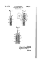
Figure 1 is a view in longitudinal section of a portion of a tubular type heater prior to applil cation of a terminal seal,
Fig. 2 is like Fig. 1 but showing the heater at one stage during the application of a terminal seal, and showing in broken lines parts of the processing apparatus which may be employed, and
end is unfilled and provides a recess I0 to receive the component elements of the terminal seal.
The insulating material 1 may be of any of the well-known types of refractory materials, such as magnesium oxide and it is assumed that the heater has been completely worked as by swaging to the desired cross-sectional dimensions and also formed in the desired configuration. It is further assumed that the heater has been subjected to an annealing treatment to remove the stresses incurred during working and to remove the greater percentage of the moisture entrained in the insulating material 1.. It is also assumed that in preparation of the application of the improved terminal seal the inner surface of sheath 8 surrounding recess Ill has been suitably cleaned.
Referring to Fig. 2 a quantity of glass frit Il preferably in powdered form is placed in recess I 0. A glass tube l2 of circular cross section is then partially inserted in recess l0 so as to have contact with and to extend into the frit I l Tube I2 is preferably greater in length than the recess I 0, and preferably has an appreciable but small clearance from the sheath 8. A metal bushing i3 preferably of steel is slipped -onto the terminal S and into the glass tube l2, said bushing having appreciable but small clearance from terminal 9 and glass tube l2.
Bushing I3 preferably is provided with an enlarged end portion I6 which is adapted to overlie the outer end of tube l2 and preferably the bushing 53 exclusive of portion IS is of the same length as tube i2.
The aforementioned clearances provided between sheath 8, tube i2, bushing I3 and the terminal 9 are desirable for sealing purposes as will later appear. Preferably the tube l2 and the bushing I3 are formed of materials having approximately the same coefficients of expansion as the material forming sheath 8 to insure maintenance of the aforementioned clearance openings during heating of the terminal end of the heater for sealing.
After the frit Il, tube l2 and bushing i3 have been assembled within recess I0 as afoi'edescribed, that portionof sheath 8 coextensive with the recess l is subjected to a localized heating to cause fusion and/or liquiflcation of the frit H and to render the tube l2 plastic, the remaining portion of the heater being maintained cool and thereby avoiding generation of troublesome gases within the body of the heater.
Preferably, the localized heating is obtained by placing the aforementioned end portion of 7the heater in a high frequency induced electromagnetic field isee broken line showing of excited coil) while supporting the heater vertically, with its terminal end uppermost, by means of a fluid cooled clamp or support (see broken line showing of clamp) immediately adjacent the portion subjected to the iield. The frequency of the field to be used can vary between 25,000 and 400,000 cycles per second; depending upon the thickness of sheath 8, the mass of bushing I3, etc. 200,000 cycles per second has been found to be a suitable average working value. It has been found that if the aforedescribed assembled elements are subjected to the latter frequency for a matter of a. few seconds, this is suillcient to cause complete fusion and liquication of the frit I I and to render tube I2 plastic.
When the heater has been thus heated, pressure is exerted inwardly on the bushing I3 towards the bottom of recess I and when the outer end of tube I 2 is engaged by the inner face of the enlarged end portion I6 of bushing I3 the tube I2 is moved inwardly therewith. This causes the fused frit to flow into the aforementioned clearance spaces between sheath 8, tube I2, bushing I3, and terminal 9. Then the terminal end of the heater is permitted to cool and in a matter of a few seconds the fused frit solidies thereby affording a bond and seal between adjacent portions respectively of sheath 8, tube I2, bushing I3 and terminal S, such bond also extending between the insulation 'I and the tube I2 and bushing i3.
Preferably, a sufficient quantity of the frit l I in powdered form is initially introduced in the recess I0 as aforedescribed to insure complete sealing throughout the perimeters and lengths of all the aforementioned clearance spaces.
The completed terminal seal which is eected by the method and means aforedescribed is shown in Fig. 3. The solidified frit is shown between the inner ends of tube I2 and bushing I3, and the insulating material 1 as II, between sheath 8 and tube I2 as IIb, between tube I2 and bushing I3 as IIC, and between bushing I3 and terminal 9 as IId.
v,As will be noted, tube I2 and bushing I3 extend beyond the end of sheath 8. The tube I2 provides a suitable electrical insulating barrier between the sheath and the bushing I3.
While the bushing I3 may be of any metallic conducting material it is preferably made of steel to insure even and rapid heating from within and without the terminal end of the heater when the latter is placed in the induction field as aforedescribed. The use of a steel bushing also enhances the strength of the completed terminal seal.
Referring to the broken line showing in Fig. 2 of the processing apparatus, the high frequency heating means is depicted schematically as comprising a heating coil supplied by a high frequency generator 2 I. prises tubing for quick cooling. Thel clamping means depicted in Fig. 2 may be assumed to comprise two clamping blocks 23 and 24 forming an annulus to bear against the sheath and having passages 25 for circulation therethrough of cooling iiuid. The two blocks are indicated as interconnected by tubing and it may be assumed that the circulating fluid enters one block and exhausts from the other. Obviously the heating means inherently tends to localize the heating of the sheath and enclosed parts and with the fluid cooled clamp it has been found that the body of the heater being sealed will remain sufficiently Preferably the coil 20 com- 4 cool to avoid generation of troublesome gases therein. n,
Whereas the sheath 8 has been described as being circular in cross sectional form, it will be apparent that a terminal seal of the aforementioned improved type may be applied to sheathed heaters of whatever cross sectional form by suitably forming the tube I2 and the bushing I3 to conform to the particular cross sectional form of the heater sheath.
Also localized heating may be effected in any other desired way, high frequency heating being preferred because of its rapidity.
What I claim as new and desire to secure by letters Patent is:
1. The method of sealing the terminal end ofA an electric heater wherein a resistor enclosed in an open end tubular sheath is embedded in insulatlon terminating at a distance from the end of the sheath to leave the sheath with an open end recess, and wherein the resistor has a terminal portion projecting through such recess to a point beyond the sheath and such terminal portion is loosely surrounded by a metal bushing lwhich in turn is loosely surrounded by an insulating tube to loosely fit within the end recess in the sheath, which comprises placing a quantity of glass frit in the end recess in the sheath, inserting into the end recess portions of the insulating tube and the metal bushing to contact the glass frit, heating locally and quickly the end of the sheath to fusevthe glass frit, and pressing into the fused glass frit the insulating tube and the metal bushing to force the fused frit into the spaces between adjacent surfaces of the sheath, the insulating tube, the metalbushing and the resistor terminal portion to seal such spaces.
2. The method of sealing the terminal end of an electric heater wherein a resistor enclosed in an open end tubular sheath is embedded in insulation terminating at a distance from the end of the sheath to leave the sheath with an open end recess, and wherein the resistor has a terminal portion projecting through such recess to a point beyond the sheath and such terminal portion is loosely surrounded by a metal bushing which in turn is loosely surrounded by an insulating tube to loosely fit within the end recess in the sheath, which comprises subjecting the sheath adjacent the point of termination of the insulation within the sheath to the influence of a cooling medium, placing a quantity of glass frit in the end recess in the sheath, inserting into the end recess portions of the insulating tube and the metal bushing to contact the glass frit, heating locally and quickly the end of the sheath to fuse the glass frit and pressing into the fused frit the insulating tube and the metal bushing to force the fused frit into the spaces between adjacent surfaces of the sheath, the insulating tube, the metal bushing and the resistor terminal portion to seal such spaces.
3. The method of sealing the terminal end of an electric heater wherein a resistor enclosed in an open end tubular sheath is embedded in insulation terminating at a distance from the end of the sheath to leave the sheath with an open end recess, and wherein the resistor has a terminal portion projecting through such recess to a. point beyond the sheath and such terminal portion is loosely surrounded by a metal bushing which in turn is loosely surrounded by an insulating tube to loosely f'lt within the end recess in the sheath, which comprises subjecting the sheath adjacent the point of termination of the insulation within the sheath to the influence of a cooling medium, placing a quantity of glass frit in the end recess in the sheath, inserting into the end recess portions of the insulating tube and the metal bushing to contact the glass frit, subjecting locally the end of the sheath to high frequency heating to flue the glass frit and pressing into the fused frit the insulating tube and the metal bushing to force the fused frit into the spaces between adjacent surfaces of the sheath, the insulating tube, the metal bushing and the resistor terminal portion to seal such spaces.
4. The method of sealing the terminal end of an electric heater wherein a resistor enclosed in an open end tubular sheath is embedded in insulation terminating at a distance from the end l of the sheath to leave the sheath with anopen end recess, and wherein the resistor has a terminal portion projecting through such recess to a point beyond the sheath and such terminal -portion is loosely surrounded by a steel bushing which in turn is loosely surrounded by a glass tube to loosely t within the end recess in the sheath, which comprises subjecting the sheath adjacent the point of termination of the insulation within the sheath to the influence of a cooling medium, placing a quantity of glass frit in the end recess in the sheath, inserting into the end recess portions of the glass tube and the steel bushing to contact the glass frit, subjecting locally the end of the sheath to high frequency heating to fuse the glass frit and pressing into the fused frit the glass tube and steel bushing to force the fused frit into the spaces between adjacent surfaces of the sheath, the glass tube, the steel bushing and the resistor terminal portion to seal such spaces.
5. The combination with a tubular heater comprising a resistor having a terminal portion, an open end tubular sheath surrounding said resistor and also its terminal portion in part, and insulation in said sheath retaining said resistor in spaced relation to said sheath, said insulation terminating at a distance from the end of said sheath leaving said sheath with an open end recess through which said terminal portion projects, of a seal for the terminal end of said heater constructed for sealing by brief heating localized thereto thereby to` avoid generation of gases within the insulation containing portion of said heater and furthermore constructed for sealing at all essential points as one operation, said seal comprising a metal bushing loosely surrounding the terminal portion of said resistor, an insulating tube loosely surrounding said bushing and havin;r clearance from said sheath, and sealing material, such seal components occupying the open end recess in said sheath and said sealing material comprising glass frit heated in situ and filling the spaces between said sheath, said insulating tube, said bushing and said terminal portion of said resistor.
6. The combination with a tubular heater comprising a resistor having a terminal portion, an open end tubular sheath surrounding said resistor and also its terminal portion in part, and insulation in said sheath retaining said resistor in spaced relation to said sheath, said insulation terminating at distance from end of said sheath leaving said sheath with an open end recess through which said terminal portion projects, of a seal for the terminal end of said heater constructed for sealing by brief heating localized thereto thereby to avoid generation of gases within the insulation containing portion of said heater and furthermore constructed for sealing at al1 essential points as one operation, said seal comprising a steel bushing loosely surrounding the terminal portion of said resistor, a glass tube loosely surrounding said bushing and having clearance from said sheath, and sealing material, such' seal components occupying the open end recess in said sheath and said sealing material comprising glass frit heated in situ and tilling the spaces between said sheath, said glass tube, said bushing and said terminal portion of said resistor.
ALLAN P. CHARBONNEAU.
REFERENCES CITED The following references file of this patent:
UNITED STATES PATENTS are of record in the Schmitt Aug. 28, 1945
Priority Applications (1)
| Application Number | Priority Date | Filing Date | Title |
|---|---|---|---|
| US757045A US2480903A (en) | 1947-06-25 | 1947-06-25 | Tubular heater terminal seal |
Applications Claiming Priority (1)
| Application Number | Priority Date | Filing Date | Title |
|---|---|---|---|
| US757045A US2480903A (en) | 1947-06-25 | 1947-06-25 | Tubular heater terminal seal |
Publications (1)
| Publication Number | Publication Date |
|---|---|
| US2480903A true US2480903A (en) | 1949-09-06 |
Family
ID=25046128
Family Applications (1)
| Application Number | Title | Priority Date | Filing Date |
|---|---|---|---|
| US757045A Expired - Lifetime US2480903A (en) | 1947-06-25 | 1947-06-25 | Tubular heater terminal seal |
Country Status (1)
| Country | Link |
|---|---|
| US (1) | US2480903A (en) |
Cited By (15)
| Publication number | Priority date | Publication date | Assignee | Title |
|---|---|---|---|---|
| US2617002A (en) * | 1951-11-27 | 1952-11-04 | Wiegand Co Edwin L | Electric heater |
| US2846537A (en) * | 1954-03-03 | 1958-08-05 | Wiegand Co Edwin L | Electric heaters |
| US2861162A (en) * | 1956-05-17 | 1958-11-18 | John Van Inthoudt | Methods of constructing sheathed electric heaters |
| US2873342A (en) * | 1955-12-05 | 1959-02-10 | Wiegand Co Edwin L | Electric heating |
| US3037266A (en) * | 1957-01-30 | 1962-06-05 | Allen Bradley Co | Method for making sealed resistors |
| US3065538A (en) * | 1956-12-05 | 1962-11-27 | Kuppers Metallwerk G M B H | Soldering method and composition |
| US3122718A (en) * | 1961-08-16 | 1964-02-25 | Wiegand Co Edwin L | Hermetically sealed, sheathed electric heating elements |
| US3183361A (en) * | 1959-08-07 | 1965-05-11 | Texas Instruments Inc | Method of making glass sealed electric circuit devices and article resulting therefrom |
| US3195093A (en) * | 1961-11-01 | 1965-07-13 | Gen Electric | Sheathed electric heating units |
| US3331913A (en) * | 1965-02-08 | 1967-07-18 | Texas Instruments Inc | Ceramic-glass sealing means for encapsulation of electrical devices |
| US3337948A (en) * | 1964-06-25 | 1967-08-29 | James H Schulman | Method of manufacture of miniature radiation dosimeters |
| US3476916A (en) * | 1967-12-11 | 1969-11-04 | American Standard Inc | Electrical heater |
| US3549451A (en) * | 1968-03-06 | 1970-12-22 | Emanuel Kugler | Method of manufacturing satchel bottom bags |
| DE29703756U1 (en) * | 1997-03-01 | 1997-04-30 | Ego Elektro Geraetebau Gmbh | Fire-proof pipe end sealing |
| USD906383S1 (en) * | 2018-08-17 | 2020-12-29 | Hotset Gmbh | Electrical heater for injection-molding machine |
Citations (5)
| Publication number | Priority date | Publication date | Assignee | Title |
|---|---|---|---|---|
| US2043196A (en) * | 1932-11-11 | 1936-06-02 | Gen Electric | Electric heater |
| US2167494A (en) * | 1936-02-28 | 1939-07-25 | Gen Electric | Electric heater |
| US2216375A (en) * | 1938-08-10 | 1940-10-01 | Breeze Corp | Resistance thermometer |
| US2372212A (en) * | 1942-03-03 | 1945-03-27 | American Electro Metal Corp | Electrical heating element |
| US2383823A (en) * | 1943-06-15 | 1945-08-28 | Gen Electric | Electric resistor |
-
1947
- 1947-06-25 US US757045A patent/US2480903A/en not_active Expired - Lifetime
Patent Citations (5)
| Publication number | Priority date | Publication date | Assignee | Title |
|---|---|---|---|---|
| US2043196A (en) * | 1932-11-11 | 1936-06-02 | Gen Electric | Electric heater |
| US2167494A (en) * | 1936-02-28 | 1939-07-25 | Gen Electric | Electric heater |
| US2216375A (en) * | 1938-08-10 | 1940-10-01 | Breeze Corp | Resistance thermometer |
| US2372212A (en) * | 1942-03-03 | 1945-03-27 | American Electro Metal Corp | Electrical heating element |
| US2383823A (en) * | 1943-06-15 | 1945-08-28 | Gen Electric | Electric resistor |
Cited By (15)
| Publication number | Priority date | Publication date | Assignee | Title |
|---|---|---|---|---|
| US2617002A (en) * | 1951-11-27 | 1952-11-04 | Wiegand Co Edwin L | Electric heater |
| US2846537A (en) * | 1954-03-03 | 1958-08-05 | Wiegand Co Edwin L | Electric heaters |
| US2873342A (en) * | 1955-12-05 | 1959-02-10 | Wiegand Co Edwin L | Electric heating |
| US2861162A (en) * | 1956-05-17 | 1958-11-18 | John Van Inthoudt | Methods of constructing sheathed electric heaters |
| US3065538A (en) * | 1956-12-05 | 1962-11-27 | Kuppers Metallwerk G M B H | Soldering method and composition |
| US3037266A (en) * | 1957-01-30 | 1962-06-05 | Allen Bradley Co | Method for making sealed resistors |
| US3183361A (en) * | 1959-08-07 | 1965-05-11 | Texas Instruments Inc | Method of making glass sealed electric circuit devices and article resulting therefrom |
| US3122718A (en) * | 1961-08-16 | 1964-02-25 | Wiegand Co Edwin L | Hermetically sealed, sheathed electric heating elements |
| US3195093A (en) * | 1961-11-01 | 1965-07-13 | Gen Electric | Sheathed electric heating units |
| US3337948A (en) * | 1964-06-25 | 1967-08-29 | James H Schulman | Method of manufacture of miniature radiation dosimeters |
| US3331913A (en) * | 1965-02-08 | 1967-07-18 | Texas Instruments Inc | Ceramic-glass sealing means for encapsulation of electrical devices |
| US3476916A (en) * | 1967-12-11 | 1969-11-04 | American Standard Inc | Electrical heater |
| US3549451A (en) * | 1968-03-06 | 1970-12-22 | Emanuel Kugler | Method of manufacturing satchel bottom bags |
| DE29703756U1 (en) * | 1997-03-01 | 1997-04-30 | Ego Elektro Geraetebau Gmbh | Fire-proof pipe end sealing |
| USD906383S1 (en) * | 2018-08-17 | 2020-12-29 | Hotset Gmbh | Electrical heater for injection-molding machine |
Similar Documents
| Publication | Publication Date | Title |
|---|---|---|
| US2480903A (en) | Tubular heater terminal seal | |
| US2489998A (en) | Electric tubular heater terminal seal | |
| CN108701910B (en) | Method and device for sealing contacts on a wire connection | |
| US2043195A (en) | Electric heater | |
| US2652622A (en) | Method of making electric heaters | |
| US2768424A (en) | Method of making a thermopile | |
| US2389587A (en) | Heating apparatus | |
| US2527890A (en) | Tubular heater terminal seal | |
| US3017483A (en) | Method of induction welding of stranded aluminum cable | |
| US1974298A (en) | Method of making a seal for electric discharge devices | |
| US4142881A (en) | Process for welding glass so that metallic elements pass through the weld bead | |
| US5298101A (en) | Method of welding together cable insulation | |
| US1992787A (en) | Electric heater | |
| US2899664A (en) | Electric heating units and methods of making the same | |
| US2273488A (en) | Method of sealing electrical conductors to quartz | |
| USRE23679E (en) | Electric tubular heater | |
| US2264817A (en) | Method of electrically severing flexible shafting | |
| US2259281A (en) | Method and apparatus for soldering connections to cable sheaths | |
| US4021770A (en) | Electrical resistance element | |
| US1270860A (en) | Electric welding process. | |
| US1298609A (en) | Sheathed-wire terminal. | |
| SU1185117A1 (en) | Method of producing the thermocouple hot junction | |
| US496592A (en) | Working brass by electricity | |
| US2475756A (en) | Method for manufacture of electrical resistances | |
| JP2678430B2 (en) | Pipe heater and manufacturing method thereof |