US2473961A - Machine or apparatus for surfacing roads - Google Patents
Machine or apparatus for surfacing roads Download PDFInfo
- Publication number
- US2473961A US2473961A US565306A US56530644A US2473961A US 2473961 A US2473961 A US 2473961A US 565306 A US565306 A US 565306A US 56530644 A US56530644 A US 56530644A US 2473961 A US2473961 A US 2473961A
- Authority
- US
- United States
- Prior art keywords
- screed
- bar
- plates
- cut
- machine
- Prior art date
- Legal status (The legal status is an assumption and is not a legal conclusion. Google has not performed a legal analysis and makes no representation as to the accuracy of the status listed.)
- Expired - Lifetime
Links
Images

Classifications
-
- E—FIXED CONSTRUCTIONS
- E01—CONSTRUCTION OF ROADS, RAILWAYS, OR BRIDGES
- E01C—CONSTRUCTION OF, OR SURFACES FOR, ROADS, SPORTS GROUNDS, OR THE LIKE; MACHINES OR AUXILIARY TOOLS FOR CONSTRUCTION OR REPAIR
- E01C19/00—Machines, tools or auxiliary devices for preparing or distributing paving materials, for working the placed materials, or for forming, consolidating, or finishing the paving
- E01C19/48—Machines, tools or auxiliary devices for preparing or distributing paving materials, for working the placed materials, or for forming, consolidating, or finishing the paving for laying-down the materials and consolidating them, or finishing the surface, e.g. slip forms therefor, forming kerbs or gutters in a continuous operation in situ
- E01C19/4866—Machines, tools or auxiliary devices for preparing or distributing paving materials, for working the placed materials, or for forming, consolidating, or finishing the paving for laying-down the materials and consolidating them, or finishing the surface, e.g. slip forms therefor, forming kerbs or gutters in a continuous operation in situ with solely non-vibratory or non-percussive pressing or smoothing means for consolidating or finishing
- E01C19/4873—Apparatus designed for railless operation
Definitions
- Our invention relates to a machine or apparatus for surfacing roads. It has to do particularly with a machine or apparatus for producing a smooth and level surface on a layer of material which is being applied to an old road surface or to a rough graded surface. More particularly, it has to do with an oscillating cut-off and compactor bar associated with a non-oscillating screed unit for application to such a machine or apparatus, and to means for supporting and operating said cut-off bar.
- the improved apparatus or machine of our invention is particularly useful in connection with the laying and/or repairing of road and other surfaces formed from various materials, such as bituminous mixes, concrete, et cetera.
- One of the objects of our invention is to provide a machine or apparatus of the foregoing character which includes an oscillata'ble cut-off and compactor bar operable at high speed to thereby give better compaction or density of the material being laid than has been possible with previously known apparatus of this general na--' ture.
- Another object of our invention is to provide a combined high speed cut-off bar and compactor of the oscillating type adapted to be associated with an ordinary non-oscillating or so-called' dead screed unit, in which the compactor and cut-off bar is movable back and 'forth in substan tially a horizontal plane lengthwise of the screed unit.
- a further object of our invention is to provide ing and cutting the newly laid-material and which eliminates the use of previously employed relatively narrow tampers which produced finehair checks on the finished surface.
- a further object of our invention is to provide an improved screed unit which is capable of easy and quick adjustments vertically and angul'a'rly with respect to the newly laid material.
- Another object of the invention is to provide an improved screed unit in which the-screed' 'is of a length corresponding to thewidth of the newly laid surface and in which -the'osc'illating 2 cut-off bar-is of somewhat shorter length and oscillatable within the limits of surface width.
- the machine or apparatus of our invention consists, preferably, of a power driven tractor unit, a screed unit'having a nonoscillatable or dead screed, and a rapidly oscillating' combined compactor and cut-off bar operatively associated with the forward or leading edge of the screed and movable back and forth lengthwise of the screed and crosswise of the machine.
- the screed is adjustable vertically with relation to the surface and is mounted fortilting movement relative to the surface, as well as for crowning adjustment. Since the cut-off bar is carried by the screed, it is likewise correspondingly adjustable vertically and angularly, that is tiltable, with relation to the surface.
- Power operated means such as an electric motor, is provided for oscillating the cut-off bar at a high rate of speed such, for example, as approximately 1000 to 1500 R. P. M.
- Fig. 1 is a side elevational view showing a machine or apparatus embodying the present invention.
- Fig. 2 is an enlarged fragmentary perspective view-of the screed unit of the machina showing the oscillating cut-01f bar of the present invention applied thereto.
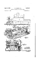
- Fig. 3 is a vertical transverse sectional View taken substantiallyalong the line 33 of Fig. 4, looking in the direction of the arrows.
- Fig. 4 is an enlarged vertical 'elevational view, partly in section and partly broken away, taken substantially along the line 4-4 in the direction of the arrows.
- Fig. 5 is a top plan view of the apparatus of Fig. 4.
- Fig 6 is an enlarged vertical sectional View taken substantially along the line 6-5 of Fig. 4 looking in the direction of the arrows.
- the machine or apparatus comprises a power driven tractor unit, shown as a whole at Ill, a trailing screed unit, shown as a whole at H, and an oscillating combined compactor and cut-off bar, shown as a whole at I2.
- the screed unit I i is connected in any suitable manner to the rear end of the tractor unit it) so as to be drawn along over the surface by said tractor unit.
- the screed unit comprises pairs of upright supporting members or channels [3 located at opposite sides of the machine and interconnected at their upper ends by cross frame members or channels Hi.
- the upper ends of each pair of channels l3 are provided with brackets i5 having bearing portions l5 through which extend vertically adjustable supporting rods or shafts ll having threaded upper end portions onto which hand wheels l8 are threaded.
- the lower ends of the rods ll carry hanger blocks 59 on which the lower portion of the screed unit, shown as a whole at 20, Fig. 2, is mounted.
- the lower portion of the screed unit 2!] comprises a pair of spaced channels 2i secured at their opposite ends to adjustable supporting plates 22 by means of off-set portions 23, Fig. 2.
- Each of the plates 22 is provided with a projec ing ear 24, Fig. 6.
- Each of the outer plates 25 carries a pair of opposed outwardly extending arms or channels 21 secured to the plates by angle clips 28, or by welding.
- the channels 21 carrying shafts 29 whose ends extend beyond the channels and into the hanger blocks I 9, Figs. 2 and 6.
- the shafts are surrounded by sleeves 29a which serve to maintain the channels in spaced relation.
- the members 27, shafts 29, blocks 19 and the rods [1 together serve to support the lower portion 20 of the screed unit for vertical adjustment which is effected by operating the hand wheels 18.
- the screed member 30 which is supported from the lower portion 20 of the screed unit by means of adjusting rods 3l secured at their lower ends to angles 32 carried by the screed 33.
- are threaded and extend through bearing sleeves 33 which in turn are supported by pairs of cross bars 34 secured to the upper flanges of the channels 2
- Nuts 35 are threaded onto the rods and engage the bearing sleeves 33, as best seen in Figs. 2 and 3.
- the rods 3! and nuts 35 provide means for adjusting the screed member 38 to the desired crown.
- the forward or lead end of the screed 35 carries an angle 36 welded thereto which extends me full length of the screed.
- a wear plate 3'5 is secured to the front face of the upright flange of the angle 36.
- a plate 38 Secured to the rear face of this flange is a plate 38 which extends the full length of the screed 30.
- the upper portion of this plate is provided with several forwardly extending roller supporting pins 39 carrying idler rollers 40, three such being shown, see. Figs. 4,
- the cut-off bar I2 is carried by a combined sup porting and wear plate [2a cooperating with the wear plate 31 of the screed.
- the plate I20. carries at its upper portion spaced hanger blocks 4! having longitudinal slots 42 formed therein. These slots receive the idler rollers of the screed, the parts being held together in operative relationship by washers 43, see Figs. 2 and 3.
- the cut-on bar is supported by the non-oscillatable or dead screed 30 for oscillating movement relative to said screed.
- the cut-off bar I2 is provided with a series of forwardly projecting teeth l2b which, as shown, are wedge-shaped and bevelled on their under surfaces. With its wedge-shape bevelled teeth oscillating at high speed as they advance, the cut-off bar contacts and crowds every bit of the material under equal pressure, works and presses stones and material into all low spots, firmly compacts the entire mass, then cuts it off clean at level of the finishing screed 35.
- the tilting of the screed may be accomplished by adjusting or moving the portion 20 including the plates 22 relative to the plates 25. Suitable means is provided for this purpose.
- the plates 25, suspended from rods 11, are provided with projecting portions 251) at their upper rear corners which provide means for supporting rotatable blocks 250.
- These blocks are provided with transverse bores having internal threads through which threaded adjustment rods 25d extend.
- the forward ends of the rods are rotatably mounted in supporting blocks 22a carried by the vertically swingable plates 22 in line with the blocks 250.
- the blocks 22a are provided.
- the plates 22 carry bolts 220 whose outer end portions extend through arcuate slots 25 and are provided with tightening nuts.
- the threaded rods 25d carry at their free ends hand wheels 25g for operating the rods to tilt the unit 25 relative to the plates 25, as shown in broken lines, Fig. 6.
- the front edge of the screed member 30 is normally maintained at a higher level than the rear edge thereof.
- Suitable power means is provided for oscillating the cut-off bar l2 at a high rate of speed. As shown, such means comprises an electric motor 44 mounted upon the channels 2!, see Figs. 2, 4'
- the motor shaft 45 carries a pulley 46 which is drivingly connected to a pulley 41 by means of a belt 48. upon a shaft 49 carrying at its forward end an eccentric 50.- A crank arm 5! is connected at one of its ends to the eccentric 50 and at its other end by a pin 52 to a bracket 53 mounted upon the supporting plate l2a. of the oscillating cut-off bar l2.
- the shaft 49 extends through the channels 2
- a stationary guard plate or shield 55 is mounted upon the forward end of the screed unit lower
- the pulley 41 is mountedportion by means of brackets 56 secured to the channels 2
- the lower end portion of the guard plate extends inwardly or rearwardly at 5511 and terminates in the region of the oscillating cut-off bar l2.
- This plate 55 serves as means for pushing the loose material ahead and protects the mechanism for operating the oscillating cut-01f bar [2.
- Floating side plates or forms 58 are mounted upon the uprights l3 at opposite ends of the screed unit. These plates are provided with vertical slots 59 with which suitable bolts 60 cooperate to permit them to have free up and down movement over the uneven road surfaces at opposite sides of the machine beyond the ends of the screed unit.
- the plates 58 provide means movable with the machine for determining the side edges of the newly laid material.
- the screed 30 extends throughout the entire width or space between the forms or plates 58. With all known prior art machines wherein the screeds themselves were oscillated, the screeds could not be long enough to bridge the space between the side plates, there being spaces left between their ends and the side plates or forms. For this reason, finishing operations were required to be performed on the edges of the new surface to correct the irregular or uneven edges of said surface.
- the high speed of oscillation of the cut-off bar [2, at approximately 1000 to 1500 R. P. M. provides for better compaction of the newly laid material due to several factors, viz: the oscillation of the 'bar, the tilt in the screed 30 and also the induced vibration from the high speed oscillation.
- a screed unit including a dead screed member extending transversely of the machine, side form plates carried by said screed unit and disposed at the ends of said dead screed member, a compacting and cut-off bar supported on said screed unit at the forward side of said dead screed member within said side form plates for engaging and compacting material into which said screed unit is crowed before the material reaches said dead screed member, said compacting and cut-off bar being supported on the screed unit for reciprocating movement thereof lengthwise of the dead screed member and transversely of the machine whereby to contact material into which the bar is crowded and compact and cut it off at a desired level, said bar being of less length than the space between said side plates so as to permit the reciprocation thereof but traversing substantially the full length of such space in its reciprocations, and means carried by the machine and operatively connected to said bar for reciprocating said bar relative to said dead screed member between said side form plates.
- cut-01f bar has its horizontal lower surface substantially level with the horizontal lower surface of the dead screed member and is provided at its forward edge with a series of forwardly projecting teeth having beveled under surfaces.
- a structure according to claim 3 including a guard plate supported by the screed unit and extending from side form plate to side form plate, said teeth on said bar projecting beneath and forwardly beyond the lower edge of said guard plate.
- Apparatus according to claim 1 wherein means is provided for supporting the compacting and cut-off bar directly from the dead screed member, said means including rollers carried by one of said members and horizontally disposed guide members carried by the other of said members.
- Apparatus according to claim 1 including means carried by the screed unit for adjusting the dead screed member vertically, and means carried by said unit for adjustably tilting said dead screed member forwardly or rearwardly.
- the vertical adjusting means comprises adjustable means for suspending both ends of the dead screed member
- the tilting means comprises vertically disposed relatively fixed plates connected with the suspending means and adjacent vertically disposed relatively tiltable plates which carry the dead screed member, and means connected with said adjacent fixed and tiltable plates for moving them relatively to tilt said dead screed member.
- Apparatus according to claim 9 including means for securing said plates in relatively adjusted positions.
Description
June 21, 1949. o. e. MANDT ET AL MACHINE OR APPARATUS FOR SURFACING ROADS 2 Sheets-Sheet -2 Filed Nov. 27. l944 v S Y mww M M R 3 m VG/ A wm i 0 A. a m 5 wmfiaum m, J 3. fin. all Y L r: a B V r cfl ma 4 W 5 I o Q n n 6 l 2 I u F n 3 F i a m 5 2 x m r l mw fi m, Flu I 6 Patented June 21, 1949 ROA Obert G. Mandt and Arnold S; Millikin, :Columbus, Ohio, assignors to The Jaeger Machine Company, Columbus, Ohio, a corporation of Ohio ApplicationNovember 2'7, 1944, Serial No. 565,306
(Cll 94-45) 10 Claims.
Our invention relates to a machine or apparatus for surfacing roads. It has to do particularly with a machine or apparatus for producing a smooth and level surface on a layer of material which is being applied to an old road surface or to a rough graded surface. More particularly, it has to do with an oscillating cut-off and compactor bar associated with a non-oscillating screed unit for application to such a machine or apparatus, and to means for supporting and operating said cut-off bar.
The improved apparatus or machine of our invention is particularly useful in connection with the laying and/or repairing of road and other surfaces formed from various materials, such as bituminous mixes, concrete, et cetera.
One of the objects of our invention is to provide a machine or apparatus of the foregoing character which includes an oscillata'ble cut-off and compactor bar operable at high speed to thereby give better compaction or density of the material being laid than has been possible with previously known apparatus of this general na--' ture.
Another object of our invention is to provide a combined high speed cut-off bar and compactor of the oscillating type adapted to be associated with an ordinary non-oscillating or so-called' dead screed unit, in which the compactor and cut-off bar is movable back and 'forth in substan tially a horizontal plane lengthwise of the screed unit.
A further object of our invention is to provide ing and cutting the newly laid-material and which eliminates the use of previously employed relatively narrow tampers which produced finehair checks on the finished surface.
A further object of our invention is to provide an improved screed unit which is capable of easy and quick adjustments vertically and angul'a'rly with respect to the newly laid material.
Another object of the invention is to provide an improved screed unit in which the-screed' 'is of a length corresponding to thewidth of the newly laid surface and in which -the'osc'illating 2 cut-off bar-is of somewhat shorter length and oscillatable within the limits of surface width.
Generally speaking the machine or apparatus of our invention consists, preferably, of a power driven tractor unit, a screed unit'having a nonoscillatable or dead screed, and a rapidly oscillating' combined compactor and cut-off bar operatively associated with the forward or leading edge of the screed and movable back and forth lengthwise of the screed and crosswise of the machine. The screed is adjustable vertically with relation to the surface and is mounted fortilting movement relative to the surface, as well as for crowning adjustment. Since the cut-off bar is carried by the screed, it is likewise correspondingly adjustable vertically and angularly, that is tiltable, with relation to the surface. Power operated means, such as an electric motor, is provided for oscillating the cut-off bar at a high rate of speed such, for example, as approximately 1000 to 1500 R. P. M.
The foregoing and other objects and advantages of our invention will be apparent from the following description and appended claims when considered in conjunction with the accompanying drawings forming a part of this specification, wherein like reference characters designate corresponding parts in the several views.
In said drawings:
Fig. 1 is a side elevational view showing a machine or apparatus embodying the present invention.
Fig. 2 is an enlarged fragmentary perspective view-of the screed unit of the machina showing the oscillating cut-01f bar of the present invention applied thereto.
Fig. 3 is a vertical transverse sectional View taken substantiallyalong the line 33 of Fig. 4, looking in the direction of the arrows.
Fig. 4 is an enlarged vertical 'elevational view, partly in section and partly broken away, taken substantially along the line 4-4 in the direction of the arrows.
Fig. 5 is a top plan view of the apparatus of Fig. 4; and
Fig 6 is an enlarged vertical sectional View taken substantially along the line 6-5 of Fig. 4 looking in the direction of the arrows.
Before explaining in detail the present invention it is to be understood that the invention is not limited'in its application to the details of construction and arrangement of parts illustrated in the accompanying drawings,-since the invention is capable of other embodiments and of being practiced or carried out in various ways.
of Fig. 1, looking- It is to be understood also that the phraseology or terminology employed herein is for the purpose of description and. not of limitation, and it is not intended to limit the invention herein claimed beyond the requirements of the prior art.
Referring now to the drawings, we have shown therein one embodiment of our present invention. In Fig. 1, the machine or apparatus comprises a power driven tractor unit, shown as a whole at Ill, a trailing screed unit, shown as a whole at H, and an oscillating combined compactor and cut-off bar, shown as a whole at I2.
The screed unit I i is connected in any suitable manner to the rear end of the tractor unit it) so as to be drawn along over the surface by said tractor unit. The screed unit comprises pairs of upright supporting members or channels [3 located at opposite sides of the machine and interconnected at their upper ends by cross frame members or channels Hi. The upper ends of each pair of channels l3 are provided with brackets i5 having bearing portions l5 through which extend vertically adjustable supporting rods or shafts ll having threaded upper end portions onto which hand wheels l8 are threaded. The lower ends of the rods ll carry hanger blocks 59 on which the lower portion of the screed unit, shown as a whole at 20, Fig. 2, is mounted.
The lower portion of the screed unit 2!] comprises a pair of spaced channels 2i secured at their opposite ends to adjustable supporting plates 22 by means of off-set portions 23, Fig. 2. Each of the plates 22 is provided with a projec ing ear 24, Fig. 6.
Forming a part of the screed unit is the screed member 30 which is supported from the lower portion 20 of the screed unit by means of adjusting rods 3l secured at their lower ends to angles 32 carried by the screed 33. The upper ends of the rods 3| are threaded and extend through bearing sleeves 33 Which in turn are supported by pairs of cross bars 34 secured to the upper flanges of the channels 2| and mounted thereon. Nuts 35 are threaded onto the rods and engage the bearing sleeves 33, as best seen in Figs. 2 and 3. The rods 3! and nuts 35 provide means for adjusting the screed member 38 to the desired crown.
The forward or lead end of the screed 35 carries an angle 36 welded thereto which extends me full length of the screed. A wear plate 3'5 is secured to the front face of the upright flange of the angle 36. Secured to the rear face of this flange is a plate 38 which extends the full length of the screed 30. The upper portion of this plate is provided with several forwardly extending roller supporting pins 39 carrying idler rollers 40, three such being shown, see. Figs. 4,
and 5.
Associated with the forward portion of the screed 30 and carried thereby for oscillation relative thereto lengthwise of the screed and transversely of the machine, is the combined compactor and cut-01f bar l2, previously mentioned. The cut-off bar I2 is carried by a combined sup porting and wear plate [2a cooperating with the wear plate 31 of the screed. The plate I20. carries at its upper portion spaced hanger blocks 4! having longitudinal slots 42 formed therein. These slots receive the idler rollers of the screed, the parts being held together in operative relationship by washers 43, see Figs. 2 and 3. Thus, it will be seen that the cut-on bar is supported by the non-oscillatable or dead screed 30 for oscillating movement relative to said screed. The cut-off bar I2 is provided with a series of forwardly projecting teeth l2b which, as shown, are wedge-shaped and bevelled on their under surfaces. With its wedge-shape bevelled teeth oscillating at high speed as they advance, the cut-off bar contacts and crowds every bit of the material under equal pressure, works and presses stones and material into all low spots, firmly compacts the entire mass, then cuts it off clean at level of the finishing screed 35.
The non-oscillating screed portion 20, in addition to being capable of vertical adjustment as mentioned above, is also capable of being tilted with relation to the newly laid surface. As best seen in Figs. 2 and 6, the tilting of the screed may be accomplished by adjusting or moving the portion 20 including the plates 22 relative to the plates 25. Suitable means is provided for this purpose. As shown, the plates 25, suspended from rods 11, are provided with projecting portions 251) at their upper rear corners which provide means for supporting rotatable blocks 250. These blocks are provided with transverse bores having internal threads through which threaded adjustment rods 25d extend. The forward ends of the rods are rotatably mounted in supporting blocks 22a carried by the vertically swingable plates 22 in line with the blocks 250. The blocks 22a. are provided with projecting headed pins 221) which extend through arcuate slots 252 formed in the relatively fixed plates 25. The plates 22 carry bolts 220 whose outer end portions extend through arcuate slots 25 and are provided with tightening nuts. The threaded rods 25d carry at their free ends hand wheels 25g for operating the rods to tilt the unit 25 relative to the plates 25, as shown in broken lines, Fig. 6.
The front edge of the screed member 30 is normally maintained at a higher level than the rear edge thereof.
Suitable power means is provided for oscillating the cut-off bar l2 at a high rate of speed. As shown, such means comprises an electric motor 44 mounted upon the channels 2!, see Figs. 2, 4'
and 5. The motor shaft 45 carries a pulley 46 which is drivingly connected to a pulley 41 by means of a belt 48. upon a shaft 49 carrying at its forward end an eccentric 50.- A crank arm 5! is connected at one of its ends to the eccentric 50 and at its other end by a pin 52 to a bracket 53 mounted upon the supporting plate l2a. of the oscillating cut-off bar l2. The shaft 49 extends through the channels 2| and is enclosed by abearing housing 54, see Fig. 3.
A stationary guard plate or shield 55 is mounted upon the forward end of the screed unit lower The pulley 41 is mountedportion by means of brackets 56 secured to the channels 2|. by bolts or the like 51. The lower end portion of the guard plate extends inwardly or rearwardly at 5511 and terminates in the region of the oscillating cut-off bar l2. This plate 55 serves as means for pushing the loose material ahead and protects the mechanism for operating the oscillating cut-01f bar [2.
Floating side plates or forms 58 are mounted upon the uprights l3 at opposite ends of the screed unit. These plates are provided with vertical slots 59 with which suitable bolts 60 cooperate to permit them to have free up and down movement over the uneven road surfaces at opposite sides of the machine beyond the ends of the screed unit. The plates 58 provide means movable with the machine for determining the side edges of the newly laid material. The screed 30 extends throughout the entire width or space between the forms or plates 58. With all known prior art machines wherein the screeds themselves were oscillated, the screeds could not be long enough to bridge the space between the side plates, there being spaces left between their ends and the side plates or forms. For this reason, finishing operations were required to be performed on the edges of the new surface to correct the irregular or uneven edges of said surface.
The high speed of oscillation of the cut-off bar [2, at approximately 1000 to 1500 R. P. M. provides for better compaction of the newly laid material due to several factors, viz: the oscillation of the 'bar, the tilt in the screed 30 and also the induced vibration from the high speed oscillation.
Having thus described our invention, what we claim is:
1. In a road-surfacing machine, a screed unit, said screed unit including a dead screed member extending transversely of the machine, side form plates carried by said screed unit and disposed at the ends of said dead screed member, a compacting and cut-off bar supported on said screed unit at the forward side of said dead screed member within said side form plates for engaging and compacting material into which said screed unit is crowed before the material reaches said dead screed member, said compacting and cut-off bar being supported on the screed unit for reciprocating movement thereof lengthwise of the dead screed member and transversely of the machine whereby to contact material into which the bar is crowded and compact and cut it off at a desired level, said bar being of less length than the space between said side plates so as to permit the reciprocation thereof but traversing substantially the full length of such space in its reciprocations, and means carried by the machine and operatively connected to said bar for reciprocating said bar relative to said dead screed member between said side form plates.
2. A structure according to claim 1 wherein said side form plates are supported for vertical floating movement directly adjacent the ends of said dead screed member.
3. A structure according to claim 1 wherein the cut-01f bar has its horizontal lower surface substantially level with the horizontal lower surface of the dead screed member and is provided at its forward edge with a series of forwardly projecting teeth having beveled under surfaces.
4. A structure according to claim 3 including a guard plate supported by the screed unit and extending from side form plate to side form plate, said teeth on said bar projecting beneath and forwardly beyond the lower edge of said guard plate.
5. A structure according to claim 1 wherein said side form plates are supported directly adjacent the ends of said dead screed member, said dead screed member and said bar having lower horizontal surfaces which are substantially at the same level, a guard plate supported by the screed unit and extending from side form plate to side form plate, said bar having a material-engaging edge projecting beneath and forwardly beyond the lower edge of said guard plate.
6. Apparatus according to claim 1 wherein means is provided for supporting the compacting and cut-off bar directly from the dead screed member, said means including rollers carried by one of said members and horizontally disposed guide members carried by the other of said members.
7. Apparatus according to claim 6 wherein an eccentric drive is provided between said dead screed member and said bar to produce reciprocation thereof, said drive being connected to a power unit carried by the screed unit.
8. Apparatus according to claim 1 including means carried by the screed unit for adjusting the dead screed member vertically, and means carried by said unit for adjustably tilting said dead screed member forwardly or rearwardly.
9. Apparatus according to claim 8 wherein the vertical adjusting means comprises adjustable means for suspending both ends of the dead screed member, and wherein the tilting means comprises vertically disposed relatively fixed plates connected with the suspending means and adjacent vertically disposed relatively tiltable plates which carry the dead screed member, and means connected with said adjacent fixed and tiltable plates for moving them relatively to tilt said dead screed member.
10. Apparatus according to claim 9 including means for securing said plates in relatively adjusted positions.
OBERT G. MANDT. ARNOLD S. MILLIKIN.
REFERENCES CITED The following references are of record in the file of this patent:
UNITED STATES PATENTS Number Name Date 1,388,690 Baker Aug. 23, 1921 2,185,645 Mose] Jan 2, 1940 2,215,455 Abernathy Sept. 2 1940 2,241,299 Finley May 6, 1941 2,248,247 Nichols July 8, 1941 2,306,125 Jackson 1- Dec. 22, 1942 2,351,592 Barber June 20, 1944
Priority Applications (1)
| Application Number | Priority Date | Filing Date | Title |
|---|---|---|---|
| US565306A US2473961A (en) | 1944-11-27 | 1944-11-27 | Machine or apparatus for surfacing roads |
Applications Claiming Priority (1)
| Application Number | Priority Date | Filing Date | Title |
|---|---|---|---|
| US565306A US2473961A (en) | 1944-11-27 | 1944-11-27 | Machine or apparatus for surfacing roads |
Publications (1)
| Publication Number | Publication Date |
|---|---|
| US2473961A true US2473961A (en) | 1949-06-21 |
Family
ID=24258028
Family Applications (1)
| Application Number | Title | Priority Date | Filing Date |
|---|---|---|---|
| US565306A Expired - Lifetime US2473961A (en) | 1944-11-27 | 1944-11-27 | Machine or apparatus for surfacing roads |
Country Status (1)
| Country | Link |
|---|---|
| US (1) | US2473961A (en) |
Cited By (17)
| Publication number | Priority date | Publication date | Assignee | Title |
|---|---|---|---|---|
| US2589257A (en) * | 1948-07-01 | 1952-03-18 | Jaeger Machine Co | Road-finishing machine |
| US2589256A (en) * | 1948-07-01 | 1952-03-18 | Jaeger Machine Co | Road-paving machine |
| US2591502A (en) * | 1949-04-02 | 1952-04-01 | Jaeger Machine Co | Road paving machine |
| US2947230A (en) * | 1957-02-21 | 1960-08-02 | Poor & Co | Bituminous paver |
| US3035499A (en) * | 1955-02-02 | 1962-05-22 | Domenighetti Costante | Finisher for laying and tamping bituminous conglomerates over road pavings |
| US3051062A (en) * | 1959-09-11 | 1962-08-28 | Jaeger Machine Co | Screed unit and suspending means |
| US3080798A (en) * | 1958-07-15 | 1963-03-12 | Blaw Knox Co | Adjustable screed and adjustment linkage therefor |
| US3453988A (en) * | 1967-10-09 | 1969-07-08 | Shell Oil Co | Portable flooring spreader |
| US4741643A (en) * | 1983-01-13 | 1988-05-03 | Allen Engineering Corporation | Laterally translatable, carriage-mounted, concrete finishing apparatus |
| US4798494A (en) * | 1987-10-28 | 1989-01-17 | Allen Engineering Corporation | Floating vibrational screed |
| WO1992020870A1 (en) * | 1991-05-17 | 1992-11-26 | Caterpillar Paving Products Inc. | Tow point for an asphalt paver |
| US6129481A (en) * | 1998-03-31 | 2000-10-10 | Delaware Capital Formation, Inc. | Screed assembly and oscillating member kit therefor |
| US20030161684A1 (en) * | 2002-02-27 | 2003-08-28 | Quenzi Philip J. | Apparatus and method for subgrade preparation |
| US20060008323A1 (en) * | 2004-07-06 | 2006-01-12 | Torvinen Jeffrey W | Apparatus and method for subgrade preparation |
| US8764342B1 (en) | 2013-02-14 | 2014-07-01 | Caterpillar Paving Products Inc. | System and method for mounting wear bar to screed assembly |
| US9982402B2 (en) * | 2014-08-25 | 2018-05-29 | Gaeart Co., Ltd. | Paving construction method, pavement structure, and longitudinal groove forming instrument for pavement |
| US10100537B1 (en) | 2017-06-20 | 2018-10-16 | Allen Engineering Corporation | Ventilated high capacity hydraulic riding trowel |
Citations (7)
| Publication number | Priority date | Publication date | Assignee | Title |
|---|---|---|---|---|
| US1388690A (en) * | 1915-08-11 | 1921-08-23 | Robert D Baker | Paving apparatus |
| US2185645A (en) * | 1938-03-21 | 1940-01-02 | Jaeger Machine Co | Road-building apparatus |
| US2215455A (en) * | 1936-12-15 | 1940-09-24 | Clyde G Abernathy | Road paver |
| US2241299A (en) * | 1937-10-30 | 1941-05-06 | Sam E Finley | Road building apparatus |
| US2248247A (en) * | 1939-11-18 | 1941-07-08 | Harry H Nichols | Screeding and floating machine for cement floors |
| US2306125A (en) * | 1941-05-05 | 1942-12-22 | Jackson Corwill | Concrete placing machine |
| US2351592A (en) * | 1940-08-01 | 1944-06-20 | Barber Greene Co | Tamper, screed, and deflector construction for road finishing machines |
-
1944
- 1944-11-27 US US565306A patent/US2473961A/en not_active Expired - Lifetime
Patent Citations (7)
| Publication number | Priority date | Publication date | Assignee | Title |
|---|---|---|---|---|
| US1388690A (en) * | 1915-08-11 | 1921-08-23 | Robert D Baker | Paving apparatus |
| US2215455A (en) * | 1936-12-15 | 1940-09-24 | Clyde G Abernathy | Road paver |
| US2241299A (en) * | 1937-10-30 | 1941-05-06 | Sam E Finley | Road building apparatus |
| US2185645A (en) * | 1938-03-21 | 1940-01-02 | Jaeger Machine Co | Road-building apparatus |
| US2248247A (en) * | 1939-11-18 | 1941-07-08 | Harry H Nichols | Screeding and floating machine for cement floors |
| US2351592A (en) * | 1940-08-01 | 1944-06-20 | Barber Greene Co | Tamper, screed, and deflector construction for road finishing machines |
| US2306125A (en) * | 1941-05-05 | 1942-12-22 | Jackson Corwill | Concrete placing machine |
Cited By (21)
| Publication number | Priority date | Publication date | Assignee | Title |
|---|---|---|---|---|
| US2589257A (en) * | 1948-07-01 | 1952-03-18 | Jaeger Machine Co | Road-finishing machine |
| US2589256A (en) * | 1948-07-01 | 1952-03-18 | Jaeger Machine Co | Road-paving machine |
| US2591502A (en) * | 1949-04-02 | 1952-04-01 | Jaeger Machine Co | Road paving machine |
| US3035499A (en) * | 1955-02-02 | 1962-05-22 | Domenighetti Costante | Finisher for laying and tamping bituminous conglomerates over road pavings |
| US2947230A (en) * | 1957-02-21 | 1960-08-02 | Poor & Co | Bituminous paver |
| US3080798A (en) * | 1958-07-15 | 1963-03-12 | Blaw Knox Co | Adjustable screed and adjustment linkage therefor |
| US3051062A (en) * | 1959-09-11 | 1962-08-28 | Jaeger Machine Co | Screed unit and suspending means |
| US3453988A (en) * | 1967-10-09 | 1969-07-08 | Shell Oil Co | Portable flooring spreader |
| US4741643A (en) * | 1983-01-13 | 1988-05-03 | Allen Engineering Corporation | Laterally translatable, carriage-mounted, concrete finishing apparatus |
| US4798494A (en) * | 1987-10-28 | 1989-01-17 | Allen Engineering Corporation | Floating vibrational screed |
| WO1992020870A1 (en) * | 1991-05-17 | 1992-11-26 | Caterpillar Paving Products Inc. | Tow point for an asphalt paver |
| US5201603A (en) * | 1991-05-17 | 1993-04-13 | Caterpillar Paving Products Inc. | Tow point for an asphalt paver |
| US6129481A (en) * | 1998-03-31 | 2000-10-10 | Delaware Capital Formation, Inc. | Screed assembly and oscillating member kit therefor |
| US6152647A (en) * | 1998-03-31 | 2000-11-28 | Delaware Capital Formation, Inc. | Screeding method incorporating oscillating member |
| US6183160B1 (en) | 1998-03-31 | 2001-02-06 | Delaware Capital Formation, Inc. | Screeding apparatus and method incorporating oscillating attachment |
| US20030161684A1 (en) * | 2002-02-27 | 2003-08-28 | Quenzi Philip J. | Apparatus and method for subgrade preparation |
| US20060008323A1 (en) * | 2004-07-06 | 2006-01-12 | Torvinen Jeffrey W | Apparatus and method for subgrade preparation |
| US7311466B2 (en) | 2004-07-06 | 2007-12-25 | Somero Enterprises, Inc. | Apparatus and method for subgrade preparation |
| US8764342B1 (en) | 2013-02-14 | 2014-07-01 | Caterpillar Paving Products Inc. | System and method for mounting wear bar to screed assembly |
| US9982402B2 (en) * | 2014-08-25 | 2018-05-29 | Gaeart Co., Ltd. | Paving construction method, pavement structure, and longitudinal groove forming instrument for pavement |
| US10100537B1 (en) | 2017-06-20 | 2018-10-16 | Allen Engineering Corporation | Ventilated high capacity hydraulic riding trowel |
Similar Documents
| Publication | Publication Date | Title |
|---|---|---|
| US2473961A (en) | Machine or apparatus for surfacing roads | |
| JP3632184B2 (en) | Paving method with asphalt mixture | |
| US4828428A (en) | Double tamping bar vibratory screed | |
| US2603132A (en) | Finishing machine for concrete slabs | |
| US3560050A (en) | Machines for removing worn road surfaces | |
| US2589257A (en) | Road-finishing machine | |
| US3396642A (en) | Subgrading machine | |
| US2380435A (en) | Combination road building machine and concrete spreader | |
| US3035499A (en) | Finisher for laying and tamping bituminous conglomerates over road pavings | |
| US2779258A (en) | Road construction machine | |
| US1467243A (en) | Road-making machine | |
| US2888864A (en) | Base paver | |
| US1840970A (en) | Road paving machine | |
| US3614916A (en) | Compacting apparatus for finishing hot mix pavement | |
| US3753621A (en) | Concrete-working machine with walking vibrators | |
| US2511589A (en) | Machine or apparatus for surfacing roads | |
| US3409330A (en) | Tandem pavement surfacing machine | |
| US2092458A (en) | Combination road machine | |
| US4312602A (en) | Wet concrete pavement spreading machine and reinforcing rod layer | |
| US3545349A (en) | Self-propelling paving machine | |
| US2426703A (en) | Machine for surface-finishing road paving | |
| US3247770A (en) | Road making | |
| US2244297A (en) | Vacuum screed | |
| US1817161A (en) | Machine for spreading and surfacing construction material | |
| US2162665A (en) | Road-building apparatus |