US2472425A - Pipe joint - Google Patents
Pipe joint Download PDFInfo
- Publication number
- US2472425A US2472425A US697891A US69789146A US2472425A US 2472425 A US2472425 A US 2472425A US 697891 A US697891 A US 697891A US 69789146 A US69789146 A US 69789146A US 2472425 A US2472425 A US 2472425A
- Authority
- US
- United States
- Prior art keywords
- pipe
- roll
- tube
- passage
- bore
- Prior art date
- Legal status (The legal status is an assumption and is not a legal conclusion. Google has not performed a legal analysis and makes no representation as to the accuracy of the status listed.)
- Expired - Lifetime
Links
- 238000001035 drying Methods 0.000 description 10
- XLYOFNOQVPJJNP-UHFFFAOYSA-N water Substances O XLYOFNOQVPJJNP-UHFFFAOYSA-N 0.000 description 6
- 238000004891 communication Methods 0.000 description 3
- 238000010276 construction Methods 0.000 description 3
- 210000004907 gland Anatomy 0.000 description 3
- 238000012856 packing Methods 0.000 description 3
- 238000010168 coupling process Methods 0.000 description 2
- 238000005859 coupling reaction Methods 0.000 description 2
- 238000003780 insertion Methods 0.000 description 2
- 230000037431 insertion Effects 0.000 description 2
- 241000969130 Atthis Species 0.000 description 1
- 101100345589 Mus musculus Mical1 gene Proteins 0.000 description 1
- 230000000295 complement effect Effects 0.000 description 1
- 230000008878 coupling Effects 0.000 description 1
- 238000011065 in-situ storage Methods 0.000 description 1
- 230000000717 retained effect Effects 0.000 description 1
- 235000002020 sage Nutrition 0.000 description 1
Images
Classifications
-
- D—TEXTILES; PAPER
- D21—PAPER-MAKING; PRODUCTION OF CELLULOSE
- D21F—PAPER-MAKING MACHINES; METHODS OF PRODUCING PAPER THEREON
- D21F5/00—Dryer section of machines for making continuous webs of paper
- D21F5/02—Drying on cylinders
- D21F5/10—Removing condensate from the interior of the cylinders
-
- Y—GENERAL TAGGING OF NEW TECHNOLOGICAL DEVELOPMENTS; GENERAL TAGGING OF CROSS-SECTIONAL TECHNOLOGIES SPANNING OVER SEVERAL SECTIONS OF THE IPC; TECHNICAL SUBJECTS COVERED BY FORMER USPC CROSS-REFERENCE ART COLLECTIONS [XRACs] AND DIGESTS
- Y10—TECHNICAL SUBJECTS COVERED BY FORMER USPC
- Y10T—TECHNICAL SUBJECTS COVERED BY FORMER US CLASSIFICATION
- Y10T403/00—Joints and connections
- Y10T403/32—Articulated members
- Y10T403/32549—Articulated members including limit means
- Y10T403/32557—Articulated members including limit means for pivotal motion
- Y10T403/32565—Ball and socket with restricted movement about one axis
- Y10T403/32573—Ball stud passes through confining opening
Definitions
- This invention relates to new and useful improvements and structural refinements in siphons, more specically, in siphons such as are employed in association with drying cylinders or rolls of paper making machines, or the like, and the principal object of the invention is to provide a device of the character herein described, which may be easily and conveniently inserted into the drying roll and which may be removed therefrom with equal expediency.
- the drying roll herein referred to usually assumes the form of a horizontally disposed, hollow cylinder which is rotatably mounted and into which steam is admitted for the purpose of drying the paper, or the like, passing therearound.
- a considerable amount of steam condenses into water which gathers in the lower portion of the roll, thereby impairing the efficiency of the drying process.
- Another object of the invention is to provide a Siphon which will not easily become damaged and which is otherwise well adapted for the purpose for which it is intended.
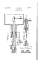
- Figure 1 is a cross sectional view of the drying roll, showing the invention in situ therein.
- Figure 2 is a cross sectional view of the invention per se
- Figure 3 is an end view, taken in the direction of the arrow 3 in Figure 2.
- the invention consists of a siphon designated generally by the reference character Ii), the same being associated with a cylindrical drying roll II. Only one end portion of this roll is shown in the drawings, and it will be noted that the roll is provided with a journal I2, the latter in turn, being formed with an axial steam passage I 3, counter-bored at the outer end thereof as at I4.
- a steam duct assuming the form of a length of pipe I5, is provided at one end thereof with an out-turned flange I6, the latter being receivable in the counter-bore I4.
- the duct I5 constitutes a continuation of the passage I3 and a suitable packing gland I'l and a packing sleeve I8 are also positioned in the counter-bore, to prevent leakage of steam.
- the gland I1 is, of course, located between the flange I 6 and the sleeve I8, and the latter is formed with a. flange IS, whereby the packing gland may be properly compressed by means of a plurality of screws and nuts 20.
- the free end of the duct or pipe I5 is screw v threaded as at 2l into one arm of a T-coupling 22, the laterally projecting arm 23 of the coupling communicating with asource of steam.
- the collar 26 is formed at one end thereof with a frusto-co'nical nose-piece 23, while its remaining end is provided with an enlarged head 29. The latter also engages the aforementioned seat 25 and the nose-piece 28 facilitates insertion of the collar 26 into the seat, as will be clearly understood.
- , is positioned in the arm 24 of the T 22 and effectively maintains the collar 26 in the seat 25 by bearing against the head 29.
- the nut 30 is provided with an outlet passage or bore 32 which communicates with the tube 2l and is screw threaded at the outer end thereof as at 33.
- a suitable hose, or the like may be secured in the threaded portion 33 for exhausting or siphoning the water through the tube 21, as will be hereinafter more clearly apparent.
- the nut 26, as a whole, is, of course, also provided with a central bore or passage 34, whereby the communication of the bore 32 with the tube 21 is facilitated.
- the tube 21 extends in a spaced relation through the duct I and through the passage I3 into the roll II andcarriesatits inner end a swivel head designated generally by the reference character 35.
- This head consists of a substantially cylindrical body 36 formed with a longitudinal bore 31 and provided at one end thereof with a cap 38.
- the cap 38 is removably secured to the body 36 by a plurality of screws 39 and is also formed with an axial passage 40 through which the tube 21 may freely pass into the bore 31.
- the remaining end of the body 36 constitutes what may be referred toas a socket member 4I and is formed with a' diametrically extending slot or recess 42.
- A- further socket member 43 assuming the form of a simple plunger, is slidably and rotatably positioned in the bore 31 and is rigidly mounted at the inner end of the tube 21, as will be clearly apparent from the accompanying drawings.
- a ball or sphere' 44' is positioned between the socket members 4
- aforementioned slot4 or recess 42 and a suitable weight 46 is adjustably secured to the pipe 45 by means of a set screw 41.
- the pipe 45 normally depends downwardly from the head 35 byvirtue-of the weight 46, and when in this position, thepipe communicates with the aforementioned tube 21- through the medium of a passage or bore 48 provided in the ball 44.
- Means are provided for urging the socket member 43A andthe ball 44 against the socket member 4I, said means consisting of a coil spring 49 positioned on the tube 21 between the member 43 and a at washer 50, the latter bearingagainst the inner end of the cap-38;
- the pipe 45 isA movable in the socket members 4I, 43 in the directiony of the arrow 5I, whereby the pipe 45 may be longitudinally aligned with the tube 21.
- a set screw 52 is provided onthe ball 44, the head of this screw engaging the slot 42.
- the device When the invention is placed in use, the device isv assembled as illustrated in Figure 1 and it will be observed that during theassembly step, the insertion of the siphon into the roll II is facilitated by simply placing the pipe 45in longitudinal alignment with the tube 21 and passing the same through the T 22, the duct I5, and the pas-- sage I3 into the-drying roll.
- the weight 46 will automatically lower the pipe to the vertical position as shown, thereby establishing communication between the tube 21 and the pipe 45, as will be clearly understood. It will be also noted that the free extremity of the pipe 45 is disposed adjacent the lateral wall of the roll I I, so that the siphoning of water from the lower portion of the roll is facilitated.
- the aforementioned socket member 43 is formed with a seat 53 which is complementary to the ball 44 and this feature, together with the provision of the spring ⁇ 43, will prevent leakage of steam or water through the flexible joint thus formed.
- the collar 26 will engage the seat 25 as has already been explained, and the entire device is securely retained together by the aforementioned nut 30.
- a drying roll siphon including a suction pipe and a delivery tube, a joint comprising a tubular body forming a, socket in one end thereof, said socket being provided with a slot extending diametrically of said body, said pipe extend-v ing through said slot, a ball movable in said socket and secured to said pipe, said tube extending through the remaining end of said body and communicating with said pipe through the medium of said ball, and a spring-pressed follower in said body in engagement with said ball.
Landscapes
- Paper (AREA)
Description
June 7, 1949.v cfw. HOWARD 2,472,425
PIPE JOINT Filed Sept. 19, 194e Inventor Z2 a WIW Patented June 7, 1949 UNITED STATES PATENT OFFICE 2 Claims.
This invention relates to new and useful improvements and structural refinements in siphons, more specically, in siphons such as are employed in association with drying cylinders or rolls of paper making machines, or the like, and the principal object of the invention is to provide a device of the character herein described, which may be easily and conveniently inserted into the drying roll and which may be removed therefrom with equal expediency.
The drying roll herein referred to usually assumes the form of a horizontally disposed, hollow cylinder which is rotatably mounted and into which steam is admitted for the purpose of drying the paper, or the like, passing therearound. When the roll is in operation, a considerable amount of steam condenses into water which gathers in the lower portion of the roll, thereby impairing the efficiency of the drying process.
It is thus apparent that means must be provided ior removing the accumulated water from the drying rolls, and for this purpose, several siphoning devices are in existence which communicate with the interior of the roll through the medium of a steam passage formed in the roll journal. However, since the journal is, of course, axially disposed with respect to the roll, considerable difliculty has been experienced in insorting the Siphon through the axially disposed journal passage and establishing communication with the body of water accumulated in the lower portion of the roll. Additional difficulties were also encountered in reducing the size of the siphon so as to prevent interference with free passage of steam.
Itis, therefore, a further object of the invention to eliminate the disadvantages above set forth and to provide a siphon which is simple in construction, dependable in operation, and which may be easily manipulated.
Another object of the invention is to provide a Siphon which will not easily become damaged and which is otherwise weil adapted for the purpose for which it is intended.
With the above more important objects in view, and such other objects as may become apparent as this specification proceeds, the invention con-` sists essentially of the arrangement and construction of parts as illustrated in the accompanying drawings, in which:
Figure 1 is a cross sectional view of the drying roll, showing the invention in situ therein.
Figure 2 is a cross sectional view of the invention per se, and
Figure 3 is an end view, taken in the direction of the arrow 3 in Figure 2.
Like characters of reference are used to designate like parts in the specification and throughout the several views.
Referring now to the accompanying drawings in detail, the invention consists of a siphon designated generally by the reference character Ii), the same being associated with a cylindrical drying roll II. Only one end portion of this roll is shown in the drawings, and it will be noted that the roll is provided with a journal I2, the latter in turn, being formed with an axial steam passage I 3, counter-bored at the outer end thereof as at I4.
A steam duct, assuming the form of a length of pipe I5, is provided at one end thereof with an out-turned flange I6, the latter being receivable in the counter-bore I4. It will be observed that the duct I5 constitutes a continuation of the passage I3 and a suitable packing gland I'l and a packing sleeve I8 are also positioned in the counter-bore, to prevent leakage of steam. The gland I1 is, of course, located between the flange I 6 and the sleeve I8, and the latter is formed with a. flange IS, whereby the packing gland may be properly compressed by means of a plurality of screws and nuts 20.
The free end of the duct or pipe I5 is screw v threaded as at 2l into one arm of a T-coupling 22, the laterally projecting arm 23 of the coupling communicating with asource of steam.
The remaining arm 24 of the T 22, that is, the arm which is longitudinally aligned with the duct I5, is formed with an annular seat 25, this being adapted to removably receivea cylindrical collar 26 secured to one end of a substantially straight tube 21. The collar 26 is formed at one end thereof with a frusto-co'nical nose-piece 23, while its remaining end is provided with an enlarged head 29. The latter also engages the aforementioned seat 25 and the nose-piece 28 facilitates insertion of the collar 26 into the seat, as will be clearly understood.
A retaining nut 30, screw threaded as at 3|, is positioned in the arm 24 of the T 22 and effectively maintains the collar 26 in the seat 25 by bearing against the head 29. It will be noted that the nut 30 is provided with an outlet passage or bore 32 which communicates with the tube 2l and is screw threaded at the outer end thereof as at 33. A suitable hose, or the like (not shown) may be secured in the threaded portion 33 for exhausting or siphoning the water through the tube 21, as will be hereinafter more clearly apparent. The nut 26, as a whole, is, of course, also provided with a central bore or passage 34, whereby the communication of the bore 32 with the tube 21 is facilitated.
The tube 21 extends in a spaced relation through the duct I and through the passage I3 into the roll II andcarriesatits inner end a swivel head designated generally by the reference character 35. This head consists of a substantially cylindrical body 36 formed with a longitudinal bore 31 and provided at one end thereof with a cap 38.
The cap 38 is removably secured to the body 36 by a plurality of screws 39 and is also formed with an axial passage 40 through which the tube 21 may freely pass into the bore 31.
The remaining end of the body 36 constitutes what may be referred toas a socket member 4I and is formed with a' diametrically extending slot or recess 42. A- further socket member 43, assuming the form of a simple plunger, is slidably and rotatably positioned in the bore 31 and is rigidly mounted at the inner end of the tube 21, as will be clearly apparent from the accompanying drawings.
A ball or sphere' 44' is positioned between the socket members 4| and 43 and isrigidly mounted at one end of a suction pipe 45; This pipe projects outwardly from the bodyl 36 through the.
aforementioned slot4 or recess 42 and a suitable weight 46 is adjustably secured to the pipe 45 by means of a set screw 41.
The pipe 45 normally depends downwardly from the head 35 byvirtue-of the weight 46, and when in this position, thepipe communicates with the aforementioned tube 21- through the medium of a passage or bore 48 provided in the ball 44.
Means are provided for urging the socket member 43A andthe ball 44 against the socket member 4I, said means consisting of a coil spring 49 positioned on the tube 21 between the member 43 and a at washer 50, the latter bearingagainst the inner end of the cap-38;
It will be readily understood that the pipe 45 isA movable in the socket members 4I, 43 in the directiony of the arrow 5I, whereby the pipe 45 may be longitudinally aligned with the tube 21. To maintain the bore 48 in, alignment with the tube 21 when the device is in the position shown in Figure 2, and to-guide the, pipe 45 in its movement as shownV by the arrow 5|, a set screw 52 is provided onthe ball 44, the head of this screw engaging the slot 42.
When the invention is placed in use, the device isv assembled as illustrated in Figure 1 and it will be observed that during theassembly step, the insertion of the siphon into the roll II is facilitated by simply placing the pipe 45in longitudinal alignment with the tube 21 and passing the same through the T 22, the duct I5, and the pas-- sage I3 into the-drying roll.
As soon as the head emerges from the inner end of the passage I3, the weight 46 will automatically lower the pipe to the vertical position as shown, thereby establishing communication between the tube 21 and the pipe 45, as will be clearly understood. It will be also noted that the free extremity of the pipe 45 is disposed adjacent the lateral wall of the roll I I, so that the siphoning of water from the lower portion of the roll is facilitated.
The aforementioned socket member 43 is formed with a seat 53 which is complementary to the ball 44 and this feature, together with the provision of the spring` 43, will prevent leakage of steam or water through the flexible joint thus formed.
After the Siphon has been installed in position, the collar 26 will engage the seat 25 as has already been explained, and the entire device is securely retained together by the aforementioned nut 30.
It is believed that the advantages and use of the invention will be clearly understood from the aforegoing disclosure and accordingly, further description thereof atthis point is considered unnecessary.
While in the foregoing there has been shown and described the preferred embodiment of this invention it is to be understood that minor changes in the details of construction, combination and arrangement of parts may be resorted to without departing from the spirit and scope of the invention as claimed.
What I claim as my invention is:
1. In a drying roll siphon including a suction pipe and a delivery tube, a joint comprising a tubular body forming a, socket in one end thereof, said socket being provided with a slot extending diametrically of said body, said pipe extend-v ing through said slot, a ball movable in said socket and secured to said pipe, said tube extending through the remaining end of said body and communicating with said pipe through the medium of said ball, and a spring-pressed follower in said body in engagement with said ball.
2. The device as. defined in claim 1 wherein said ball is formed with a pair of connecting radial passages disposed substantially at right angles to each other, one of said passages communicating with said pipe and the remaining passage communicating with. said tube, and a detent provided on said ball and engaging said slot.
CHARLES W. HOWARD.
REFERENCES CITED The following references are of record in the le of this patent:
UNITED STATES PATENTS Number Name Date 1,503,125 Iddings July 29, 1924 2,000,087 Meeker et al May 7, 1935 2,056,562 Bridge Oct. 6, 1936 2,299,530 Cram Oct. 20, 1942
Priority Applications (1)
| Application Number | Priority Date | Filing Date | Title |
|---|---|---|---|
| US697891A US2472425A (en) | 1946-09-19 | 1946-09-19 | Pipe joint |
Applications Claiming Priority (1)
| Application Number | Priority Date | Filing Date | Title |
|---|---|---|---|
| US697891A US2472425A (en) | 1946-09-19 | 1946-09-19 | Pipe joint |
Publications (1)
| Publication Number | Publication Date |
|---|---|
| US2472425A true US2472425A (en) | 1949-06-07 |
Family
ID=24803012
Family Applications (1)
| Application Number | Title | Priority Date | Filing Date |
|---|---|---|---|
| US697891A Expired - Lifetime US2472425A (en) | 1946-09-19 | 1946-09-19 | Pipe joint |
Country Status (1)
| Country | Link |
|---|---|
| US (1) | US2472425A (en) |
Cited By (4)
| Publication number | Priority date | Publication date | Assignee | Title |
|---|---|---|---|---|
| US2685370A (en) * | 1950-09-02 | 1954-08-03 | Escher Wyss Ag | Centrifugal machine for continuous operation |
| US2926527A (en) * | 1958-03-07 | 1960-03-01 | Cons Edison Co New York Inc | Fluid sampling apparatus |
| US4068865A (en) * | 1975-12-29 | 1978-01-17 | Vetco Offshore, Inc. | Pipe connectors |
| US4691452A (en) * | 1986-07-18 | 1987-09-08 | Duff Norton Company | Articulable siphon tube assembly for dryer drum |
Citations (4)
| Publication number | Priority date | Publication date | Assignee | Title |
|---|---|---|---|---|
| US1503125A (en) * | 1919-04-10 | 1924-07-29 | Fyr Fyter Co | Fire extinguisher with a single delivery tube |
| US2000087A (en) * | 1931-12-31 | 1935-05-07 | Black Clawson Co | Siphon |
| US2056562A (en) * | 1934-03-10 | 1936-10-06 | Black Clawson Co | Paper machinery |
| US2299530A (en) * | 1937-09-16 | 1942-10-20 | Hervey G Cram | Siphon for drier drainage systems |
-
1946
- 1946-09-19 US US697891A patent/US2472425A/en not_active Expired - Lifetime
Patent Citations (4)
| Publication number | Priority date | Publication date | Assignee | Title |
|---|---|---|---|---|
| US1503125A (en) * | 1919-04-10 | 1924-07-29 | Fyr Fyter Co | Fire extinguisher with a single delivery tube |
| US2000087A (en) * | 1931-12-31 | 1935-05-07 | Black Clawson Co | Siphon |
| US2056562A (en) * | 1934-03-10 | 1936-10-06 | Black Clawson Co | Paper machinery |
| US2299530A (en) * | 1937-09-16 | 1942-10-20 | Hervey G Cram | Siphon for drier drainage systems |
Cited By (4)
| Publication number | Priority date | Publication date | Assignee | Title |
|---|---|---|---|---|
| US2685370A (en) * | 1950-09-02 | 1954-08-03 | Escher Wyss Ag | Centrifugal machine for continuous operation |
| US2926527A (en) * | 1958-03-07 | 1960-03-01 | Cons Edison Co New York Inc | Fluid sampling apparatus |
| US4068865A (en) * | 1975-12-29 | 1978-01-17 | Vetco Offshore, Inc. | Pipe connectors |
| US4691452A (en) * | 1986-07-18 | 1987-09-08 | Duff Norton Company | Articulable siphon tube assembly for dryer drum |
Similar Documents
| Publication | Publication Date | Title |
|---|---|---|
| US3554659A (en) | Paint applicator roll with internal paint supply | |
| US2472425A (en) | Pipe joint | |
| US2482687A (en) | Service tau | |
| US2101938A (en) | Lubricated swivel pipe joint | |
| US2062519A (en) | Testing plug | |
| US1760704A (en) | Sink-pipe cleaner | |
| US2334395A (en) | Fire hose nozzle | |
| US2177429A (en) | Shower pipe cleaner | |
| US2135148A (en) | Suction apparatus | |
| GB230949A (en) | Improved means for supporting hose and like flexible pipes, particularly applicable to fire-extinguishing | |
| US1727962A (en) | Spraying device | |
| US2830563A (en) | Automatic jack leg | |
| US1159977A (en) | Valve-cleaner. | |
| US2651511A (en) | Device for tempering steam | |
| US2044699A (en) | Lifting jack | |
| US1128156A (en) | Hose-billing press. | |
| US2389486A (en) | Homogenizing machine | |
| US2143296A (en) | Cleaning nozzle | |
| US2574756A (en) | Means for injecting a flowable substance into a stream of liquid | |
| US2643739A (en) | Relief device for lubricating systems | |
| US2164552A (en) | Fluid operated vacuum device | |
| US2101937A (en) | Swivel pipe joint | |
| US1887561A (en) | Sleeve steamer | |
| US2998845A (en) | Foam killing spray system for vacuum control assembly | |
| DE894089C (en) | Combined steam jet and air suction valve for clothes ironing machines |