US2467663A - Saddle stirrup hanger - Google Patents
Saddle stirrup hanger Download PDFInfo
- Publication number
- US2467663A US2467663A US767484A US76748447A US2467663A US 2467663 A US2467663 A US 2467663A US 767484 A US767484 A US 767484A US 76748447 A US76748447 A US 76748447A US 2467663 A US2467663 A US 2467663A
- Authority
- US
- United States
- Prior art keywords
- sleeve
- saddle
- hanger
- tree
- stirrup
- Prior art date
- Legal status (The legal status is an assumption and is not a legal conclusion. Google has not performed a legal analysis and makes no representation as to the accuracy of the status listed.)
- Expired - Lifetime
Links
- 238000010276 construction Methods 0.000 description 3
- 238000005452 bending Methods 0.000 description 1
- 239000004568 cement Substances 0.000 description 1
Images
Classifications
-
- B—PERFORMING OPERATIONS; TRANSPORTING
- B68—SADDLERY; UPHOLSTERY
- B68C—SADDLES; STIRRUPS
- B68C1/00—Saddling equipment for riding- or pack-animals
- B68C1/16—Fastening stirrups to saddles; Stirrup-leathers
Definitions
- This invention relates to saddles and is particularly adapted to be used in connection with saddles used in range riding, breaking or bucking saddles and work saddles.
- the primary object of the invention is to attach the stirrups to the saddle in such a manner as to increase the freedom of stirrup swing and their operation without interference from the rigging.
- a further object of the invention is to increase the swing of the stirrup with a minimum of efiort and without bending or deforming the stirrup leathers.
- Figure 1 is a side view of a working saddle, partially broken away for illustrating my new and improved stirrup mounting.
- FIG. 2 is an enlarged fragmentary sectional view of the stirrup mounting, taken on line 2-2 of Figure 1.
- Figure 3 is a perspective view of the mount fitting which is adapted to be mounted within the saddle tree.
- Figure 4 illustrates in perspective the fitting that is associated with the fitting indicated in Figure 3 and that is fixedly secured to the stirrup hanger.
- Figure 5 is a fragmentary perspective view of the upper end of the stirrup hanger.
- the saddle is indicated in general by numeral I and is of the type that is employed for range riding, bucking, breaking and working.
- the saddle tree is indicated at 2 and is of the usual construction. Fixedly mounted within the saddle tree 2 is the fitting or hearing 3 which is secured in place by the screws 4 passing through the holes 5 located in the ofiset flange B forming part of the sleeve 1 of the fitting 3. The fitting 3 is further secured within the saddle tree 2 by the knurling 3B and cement 3A.
- a spindle fitting 8 is journalled within the sleeve 1 and has a flange 9 for contacting the end IU of the sleeve 1. This flange also rests upon the saddle skirt ll best illustrated in Figure 2.
- the opposite end of the spindle 8 has a cone shaped bearing 12 formed therein, adapted to receive the cone I3 formed on the underside of the hanger l4 (Figs. 4 and 5).
- the hanger and its cone I3 are maintained within the cone recess I2 of the spindle 8 by the screwv l5, which is threaded within the spindle. Suflicient clearance I6 is provided between the hanger and the flange 6 to permit freedom of 2 movement.
- the stirrup leathers H are secured to the hanger M by the rivets I8.
- the fender portion 19 is also secured to the upper rivets I8. I do not wish to be limited to any particular type of stirrup straps or fenders as any well known stirrup assembly may be employed.
- a saddle comprising a tree and a seat including a sub-seat, an aperture formed in said tree beneath said seat and adjacent said sub-seat, an internally threaded bearing sleeve mounted in said aperture and having an outwardly extending flange underlying said tree, the outer end of said sleeve being conically recessed, a stirrup hanger transversely overlying the outer end of said sleeve and having an aperture aligned with the threaded bore of said bearing sleeve, and a conically headed screw extending through said aperture and threaded in said bearing sleeve to bind said hanger between the cone of said screw head and the conical wall of said recess.
- a saddle including a tree, a seat, a sub-seat, an aperture formed in the tree beneath said seat and adjacent said sub-seat, av bearing sleeve fitted in said aperture and having a flange at its outer end which overlies the tree and is secured thereto,
- a rotatable sleeve fitted in the bearing sleeve said rotatable sleeve having a flange at its inner end to overlie the inner end of the bearing sleeve and tree, the outer end of the rotatable sleeve extending slightly above the outer end of the bearing sleeve and formed with a cone-shaped recess, a stirrup hanger overlying the upper ends of the bearing sleeve and rotatable sleeve, said hanger having a cone-shaped projection to engage in the cone-shaped recess in the rotatable sleeve, and a screw engaging an opening formed in the hanger and through the cone-shaped projection and a threaded opening formed in the rotatable bearing whereby the stirrup hanger may oscillate with the rotatable sleeve independently of the bearing sleeve.
- a saddle comprising a tree and a seat including a sub-seat, an aperture formed in said tree, a bearing composed of an inner sleeve and an outer sleeve, mounted in the aperture, the inner sleeve having a flange engaging the inner surface of the tree and overlapping the inner end of the outer sleeve, the outer sleeve having a. flange to engage HERBERT L. FUNK.
Landscapes
- Engineering & Computer Science (AREA)
- Mechanical Engineering (AREA)
- Mutual Connection Of Rods And Tubes (AREA)
Description
April 19, 1949. H.1 FUNK SADDLE STIRRUP HANGER Filed Aug. '8, 1947 INVENTOR. HERBERT L. FU NK ATTORNEY Patented Apr. 19,1949
UNITED STATES PATENT OFFICE SADDLE STIRRUP HANGER Herbert .L. Funk, Philomath, Greg.
Application August 8, 1947, Serial No. 767,484
Claims.
This invention relates to saddles and is particularly adapted to be used in connection with saddles used in range riding, breaking or bucking saddles and work saddles.
The primary object of the invention is to attach the stirrups to the saddle in such a manner as to increase the freedom of stirrup swing and their operation without interference from the rigging.
A further object of the invention is to increase the swing of the stirrup with a minimum of efiort and without bending or deforming the stirrup leathers.
These and other incidental objects will be apparent in the drawings, specification and claims.
Referring to the drawings:
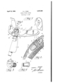
Figure 1 is a side view of a working saddle, partially broken away for illustrating my new and improved stirrup mounting.
Figure 2 is an enlarged fragmentary sectional view of the stirrup mounting, taken on line 2-2 of Figure 1.
Figure 3 is a perspective view of the mount fitting which is adapted to be mounted within the saddle tree.
Figure 4 illustrates in perspective the fitting that is associated with the fitting indicated in Figure 3 and that is fixedly secured to the stirrup hanger.
Figure 5 is a fragmentary perspective view of the upper end of the stirrup hanger.
In the drawings:
The saddle is indicated in general by numeral I and is of the type that is employed for range riding, bucking, breaking and working. The saddle tree is indicated at 2 and is of the usual construction. Fixedly mounted within the saddle tree 2 is the fitting or hearing 3 which is secured in place by the screws 4 passing through the holes 5 located in the ofiset flange B forming part of the sleeve 1 of the fitting 3. The fitting 3 is further secured within the saddle tree 2 by the knurling 3B and cement 3A.
A spindle fitting 8 is journalled within the sleeve 1 and has a flange 9 for contacting the end IU of the sleeve 1. This flange also rests upon the saddle skirt ll best illustrated in Figure 2. The opposite end of the spindle 8 has a cone shaped bearing 12 formed therein, adapted to receive the cone I3 formed on the underside of the hanger l4 (Figs. 4 and 5).
The hanger and its cone I3 are maintained within the cone recess I2 of the spindle 8 by the screwv l5, which is threaded within the spindle. Suflicient clearance I6 is provided between the hanger and the flange 6 to permit freedom of 2 movement. The stirrup leathers H are secured to the hanger M by the rivets I8. The fender portion 19 is also secured to the upper rivets I8. I do not wish to be limited to any particular type of stirrup straps or fenders as any well known stirrup assembly may be employed.
By observing Figure 1 it will be noted that the hanger and stirrup assembly has considerable freedom of swing. The sub-seat 20 of the saddle is cut away at 2| allowing the hanger [4 to operate in this space freely swinging through the action of the spindle 8 revolving in the bearing 1 of the fitting 3.
With my new and improved stirrup mounting it will be noted that the same comes over the top of the rigging ring 22 and the rigging straps 23. This is what allows for the freedom of operation or swing of my stirrup mounting and it is, as stated above, the primary object of my invention.
I do not wish to be limited to the exact mechanical details as other mechanical equivalents may be substituted still coming within the scope of my claims.
What I claim as new is:
1. In a saddle comprising a tree and a seat including a sub-seat, an aperture formed in said tree beneath said seat and adjacent said sub-seat, an internally threaded bearing sleeve mounted in said aperture and having an outwardly extending flange underlying said tree, the outer end of said sleeve being conically recessed, a stirrup hanger transversely overlying the outer end of said sleeve and having an aperture aligned with the threaded bore of said bearing sleeve, and a conically headed screw extending through said aperture and threaded in said bearing sleeve to bind said hanger between the cone of said screw head and the conical wall of said recess.
2. A saddle construction as set forth in claim 1, wherein the overlying flange of said outer sleeve is rigidly secured to said tree.
3. A saddle construction as set forth in claim 1, wherein a sleeve is telescoped around said bearing sleeve and has an outwardly extending flange overlying said tree, the outer surface of saidsleeve being roughened to adhere to the wall of the tree aperture.
4. A saddle including a tree, a seat, a sub-seat, an aperture formed in the tree beneath said seat and adjacent said sub-seat, av bearing sleeve fitted in said aperture and having a flange at its outer end which overlies the tree and is secured thereto,
a rotatable sleeve fitted in the bearing sleeve, said rotatable sleeve having a flange at its inner end to overlie the inner end of the bearing sleeve and tree, the outer end of the rotatable sleeve extending slightly above the outer end of the bearing sleeve and formed with a cone-shaped recess, a stirrup hanger overlying the upper ends of the bearing sleeve and rotatable sleeve, said hanger having a cone-shaped projection to engage in the cone-shaped recess in the rotatable sleeve, and a screw engaging an opening formed in the hanger and through the cone-shaped projection and a threaded opening formed in the rotatable bearing whereby the stirrup hanger may oscillate with the rotatable sleeve independently of the bearing sleeve.
5. A saddle comprising a tree and a seat including a sub-seat, an aperture formed in said tree, a bearing composed of an inner sleeve and an outer sleeve, mounted in the aperture, the inner sleeve having a flange engaging the inner surface of the tree and overlapping the inner end of the outer sleeve, the outer sleeve having a. flange to engage HERBERT L. FUNK.
REFERENCES CITED The following references are of record in the file of this patent:
UNITED STATES PATENTS Number Name Date 2,207,982 Hamley July 16, 1940 FOREIGN PATENTS Number Country Date 14,289 Great Britain 1886
Priority Applications (1)
| Application Number | Priority Date | Filing Date | Title |
|---|---|---|---|
| US767484A US2467663A (en) | 1947-08-08 | 1947-08-08 | Saddle stirrup hanger |
Applications Claiming Priority (1)
| Application Number | Priority Date | Filing Date | Title |
|---|---|---|---|
| US767484A US2467663A (en) | 1947-08-08 | 1947-08-08 | Saddle stirrup hanger |
Publications (1)
| Publication Number | Publication Date |
|---|---|
| US2467663A true US2467663A (en) | 1949-04-19 |
Family
ID=25079628
Family Applications (1)
| Application Number | Title | Priority Date | Filing Date |
|---|---|---|---|
| US767484A Expired - Lifetime US2467663A (en) | 1947-08-08 | 1947-08-08 | Saddle stirrup hanger |
Country Status (1)
| Country | Link |
|---|---|
| US (1) | US2467663A (en) |
Cited By (5)
| Publication number | Priority date | Publication date | Assignee | Title |
|---|---|---|---|---|
| US2624167A (en) * | 1951-02-27 | 1953-01-06 | Porter Saddle And Harness Comp | Saddle structure |
| US2730853A (en) * | 1953-08-31 | 1956-01-17 | Tex Tan Of Yoakum | Stirrup leather attaching means for saddles |
| US2845766A (en) * | 1957-10-04 | 1958-08-05 | Frank H Leddy | Saddle |
| WO2003011746A1 (en) * | 2001-08-02 | 2003-02-13 | James, Beverley, Joan | A rotatable stirrup bar for a saddle tree |
| USD591010S1 (en) * | 2008-04-17 | 2009-04-21 | Sabine Ullmann | Treeless saddle |
Citations (1)
| Publication number | Priority date | Publication date | Assignee | Title |
|---|---|---|---|---|
| US2207982A (en) * | 1939-02-18 | 1940-07-16 | Lester H Hamley | Saddletree and rigging therefor |
-
1947
- 1947-08-08 US US767484A patent/US2467663A/en not_active Expired - Lifetime
Patent Citations (1)
| Publication number | Priority date | Publication date | Assignee | Title |
|---|---|---|---|---|
| US2207982A (en) * | 1939-02-18 | 1940-07-16 | Lester H Hamley | Saddletree and rigging therefor |
Cited By (7)
| Publication number | Priority date | Publication date | Assignee | Title |
|---|---|---|---|---|
| US2624167A (en) * | 1951-02-27 | 1953-01-06 | Porter Saddle And Harness Comp | Saddle structure |
| US2730853A (en) * | 1953-08-31 | 1956-01-17 | Tex Tan Of Yoakum | Stirrup leather attaching means for saddles |
| US2845766A (en) * | 1957-10-04 | 1958-08-05 | Frank H Leddy | Saddle |
| WO2003011746A1 (en) * | 2001-08-02 | 2003-02-13 | James, Beverley, Joan | A rotatable stirrup bar for a saddle tree |
| US20060144023A1 (en) * | 2001-08-02 | 2006-07-06 | James Trevor G | Rotatable stirrup bar for a saddle tree |
| US7472530B2 (en) | 2001-08-02 | 2009-01-06 | Trevor Graham James | Rotatable stirrup bar for a saddle tree |
| USD591010S1 (en) * | 2008-04-17 | 2009-04-21 | Sabine Ullmann | Treeless saddle |
Similar Documents
| Publication | Publication Date | Title |
|---|---|---|
| US694875A (en) | Bicycle-saddle. | |
| US2467663A (en) | Saddle stirrup hanger | |
| US2342449A (en) | Bridle and hackamore bit | |
| US3981124A (en) | Concho | |
| US2743461A (en) | Insert nut and flange | |
| US2418103A (en) | Adjustable stirrup suspension for saddles | |
| US2252971A (en) | Miniature saddle | |
| US1433783A (en) | Stud | |
| US1793825A (en) | Valve | |
| US662564A (en) | Riding-saddle. | |
| US1954521A (en) | Brake shoe | |
| US834201A (en) | Harness-pad. | |
| US1572796A (en) | Saddle ring | |
| US2237163A (en) | Shackle arm construction | |
| US681940A (en) | Harness-saddle. | |
| US1125533A (en) | Hame and trace connection. | |
| US457739A (en) | George newton | |
| US435537A (en) | Harness-girth | |
| US676627A (en) | Harness-saddle. | |
| US1316891A (en) | Horse-collar | |
| US424622A (en) | Shire | |
| US424625A (en) | Saddle-tree | |
| US236553A (en) | Winfield e | |
| US424623A (en) | Shire | |
| US971655A (en) | Trace and backer loop. |