US2444809A - Reverse flow cleaner - Google Patents
Reverse flow cleaner Download PDFInfo
- Publication number
- US2444809A US2444809A US572270A US57227045A US2444809A US 2444809 A US2444809 A US 2444809A US 572270 A US572270 A US 572270A US 57227045 A US57227045 A US 57227045A US 2444809 A US2444809 A US 2444809A
- Authority
- US
- United States
- Prior art keywords
- air
- dust
- flow
- compartment
- dirt
- Prior art date
- Legal status (The legal status is an assumption and is not a legal conclusion. Google has not performed a legal analysis and makes no representation as to the accuracy of the status listed.)
- Expired - Lifetime
Links
Images


Classifications
-
- A—HUMAN NECESSITIES
- A47—FURNITURE; DOMESTIC ARTICLES OR APPLIANCES; COFFEE MILLS; SPICE MILLS; SUCTION CLEANERS IN GENERAL
- A47L—DOMESTIC WASHING OR CLEANING; SUCTION CLEANERS IN GENERAL
- A47L9/00—Details or accessories of suction cleaners, e.g. mechanical means for controlling the suction or for effecting pulsating action; Storing devices specially adapted to suction cleaners or parts thereof; Carrying-vehicles specially adapted for suction cleaners
- A47L9/20—Means for cleaning filters
Definitions
- This invention relates to suction cleaners and is particularly concerned with means for the removal of accumulated dust and dirt from the dust bag or chamber of the cleaner.
- suction cleaners have long been a common element of household equipment. Most of such devices operate by the application of suction to the surface to be cleaned whereby the resulting flow of air will pick up and entrain dust, dirt and like fine particles, the air being then directed through a separating means, usually a porous receptacle such as a bag which restrains and filters out such foreign matter, the air passing through the walls of the porous member. In all such devices considerable difficulty and nuisance has been experienced in the subsequent removal of the accumulated dirt and dust from the bag or receptacle.
- a further object of the invention is to provide means whereby the porous receptacle of a suction cleaner may be discharged of its accumulated dust and dirt and whereby the walls of the receptacle are cleaned so as to insure maximum efliciency of the apparatus after discharging the foreign matter.
- Another object of the invention is to provide a cleaner including pressure operated means operable to move a piston through a dirt receiving compartment so as to eject accumulated dirt therefrom.
- a further object of the invention is to provide means for reversing the air flow of a vacuum cleaner so as to cause a reverse air flow through a dirt receiving compartment of the cleaner whereby accumulated dust and dirt will be ejected therefrom.
- the inventive concept may be defined as embracing the thought of reversing the flow of air in a suction cleaner in order to expel the accumulated dirt and foreign matter therefrom. More specifically the invention provides a valve system by which the air 'flow may be reversed and it also provides a pusher or piston which is preferably operated by such reversed air flow to move through the dust chambar and eject the dust and dirt therefrom.
- the present invention is shown applied to a vacuum cleaner of the tank type, wherein the motor, fan and dust receptacle are mounted within a single housing which is normally stationary while a suction hose conducts air flow from a suction nozzle which is movable over the surfaces to be cleaned.
- porous receptacle of the present embodiment of the invention is shown as a fixed cylindrical member. Obviously various aspects of the invention may be directly applied or modified for application to other types of cleaners and numerous variations in the structure for the removal of dust and dirt from the incoming air may be resorted to.
- Fig. 1 is a side elevation showing the cleaner as used during a cleaning operation
- Fig. 2 is a similar view showing the position of the parts when the foreign matter is being discharged from the cleaner
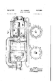
- Fig. 3 is a more detailed view with the parts in the position shown in Fig. 1;
- Fig. 4 is a sectional view taken on lines 4-4 of Fig. l;
- Fig. 5 is a sectional view taken on lines 5-5 of Fig. 2;
- Fig. 6 is a sectional view taken on lines 6-6 of Fig. 1;
- Fig. '7 is a vertical sectional view taken on lines 1-! of Fig. 2, and
- Fig. 8 is a sectional view taken on lines 8--8 of Fig. 2.
- the housing is of generally cylindrical form constituted by a body Ill which is supported on runners ll so as to be easily moved along the fioor.
- the housing encloses a rear motor compartment l2 and a forward cleaning compartment [3.
- a motor fan unit I4 is mounted within the motor compartment l2 while the forward cleaning compartment is provided with horizontally extending spider engages the outer walls of the flange to be readily removed therefrom.
- the fitting 19 extends inwardly of the flange l8 and is provided with a hose receiving adapter indicated at 23.
- the adapter 20 is adapted to receive one end of a suction hose '2! as shown in Fig. 1.
- the front face of the front end closure I! also carries a hinged retainer member 24, the pivoted element 25 of which is arcuately-iormed to conform in configuration to the curved outer surface of the flange it -(see Fig. 8).---W-hen moved downwardly the element 25 contacts the side walls of the fitting l9 and assists in retaining the fitting l9 against accidental "displacement.
- the element 25 also carries an'eyelet 26 and a button 21.
- a coil spring 28 is secured to the eyelet 2B- atone end. its opposite end being --removably secured to the.
- Thescrews 3I engage ⁇ KISSES-s35 of the plate 34, while oppoasitelyzdirect-screws 36-secure'ears 31 of a guide support--38 to thelbosses '35,the bosses, serving to space the support 38 from the plate 34.
- zinneruend ofthe receptacle i6 is secured between the plate 34 and the arms [5..whilethe riforward' end is secured between the armsjtiand an inwardly extending lip 39 of thefront end .--enclosure H.
- the support 38 carriesa forwardly extending hollow rectangular guideabar 43, within which is,
- winner-surface of thescreen iE.- Thenarrange- .zzment is'such that-when air is admitted forward- :rly through the central aperture of the plate.
- an operating link 50 is connected at one end with the slide valve 41 while its opposite upper end is connected with an externally mounted flap valve
- is mounted over an 5 intake aperture 52 of the body and is adapted to be manually moved (see Figs. 6 and 7)
- 1 the flap valve .5] is open asinll'ig. 7 air is ad- "mitted directly to the compartment l2 through the aperture 52 and suction is cut off from the .-compartment I3 by closure of the aperture 48 in the baiiie 45.
- is closed as in-Fig.
- the aperture 48 of the baflle and the aperturea49xof the lide valve are in registration nwcandsairisgdrawn through the compartment l3 5mp ssin'gsrthroughithe motor fan unit to be discharged at the rear through an elbow 53 and a 4 reciprocally-mounted port 54.
- Port 54 is mount- ..ed, on aslide 55 carried by guides 56.
- the slide 55 also carries with it.
- a vertically movable closure 51 which in the raised position as shown in 'Figs::1-'and fi-"engages irrthe-lowerend of aforwardly extending-duct- SB-to prevent the discharge of air therethrough during the cleaning operation.
- the forwardend "of the duct 58 leads to 5, the central aperture of the'plate 34.
- the present invention provides a suction cleaner operable in the normal fashion to accomplish the usual suction cleaner function, but which may be readily adjusted to provide for a reverse flow of the air through the cleaning chamber and which further provides for the action of a mechanical pusher or piston having power operated means" to cause it to move within thecleaning chamber to discharge accumulated dust and dirt therefrom.
- a portable domestic suction cleaner the combination of means for producing an air flow, a compartment for removing dust and dirt entrained by air flowing under the influence of said means, means for reversing the flow of air through said compartment, and a pusher mounted within said compartment including an impervious element responsive to reversal of air flow to be moved by such reversal to cause said pusher to move in said compartment to eject accumulated dust and dirt therefrom.
- a portable domestic suction cleaner the combination of means for producing an air flow, a compartment through which air flows under the influence of said means, a porous member in said compartment for removing dust and dirt entrained by air flowing through the compartment, means for reversing the flow of air through said compartment, and a pusher mounted within said compartment including an impervious element responsive to reversal of air flow to be moved by such reversal to cause said pusher to move in said compartment to eject accumulated dust and dirt therefrom.
- a portable domestic suction cleaner the combination of means for producing an air flow, a compartment through which air flows under the influence of said means, a fixed substantially rigid porous member in said compartment for removing dust and dirt entrained by air flowing through the compartment, means for reversing the how of air through said compartment, and a pusher mounted within said compartment including an impervious element responsive to reversal of air flow to be moved by suchreversal to cause said pusher to move in said compartment to eject accumulated dust and dirt therefrom.
- a piston within said receptacle, means for drawing dust laden air in through said compartment and receptacle whereby the walls of the receptacle will collect the dust of said air, means for reversing the flow of air through said compartment, and an impervious element engageable by the reversed air flow for moving said piston to eject dirt and dust from said receptacle.
- a piston within said receptacle, means for drawing dust laden air in through said compartment and receptacle whereby the walls of the receptacle willcollcct the; dust of said air, means for reversing theflow of air through said compartment, and an impervious element engageable bythereversed air flow for moving said piston to eject dirt and dust from said receptacle.
- a piston within.
- unidirectional impeller means for drawing dust laden air in through said compartment and receptacle where by the walls of the receptacle will collect the dust of said air
- an impervious casing means for causing a flow of air through said casing, means for reversing the flow of air through said casing, a pervious chamber within said casing through which the flow of air may be directed, and-an impervious piston within said chamber, said piston being constructed and'arranged to be actuated by the flow of air in one direction to move in said chamber to eject accumulated dust and dirt therefrom.
- an impervious casing means for causing a flow of air through said casing, means for reversing the flow of air through said casing, a horizontal pervious dust and dirt collecting chamber within said casing through which the flow of air may be directed, and an impervious piston within said chamber, said piston being constructed and arranged to be actuated by the flow of air in one direction to move in said chamber to eject accumulated dust and dirt therefrom.
- an impervious casing means for causing a flow of air through said casing, means for reversing the flow of air through said casing, a horizontal pervious dust and dirt collecting chamber within said casing through which the flow of air may be directed, an impervious piston within said chamber, said piston being constructed and arranged to be actuated by the flow of air in one direction to move in said chamber to eject accumulated dust and dirt therefrom, and a spring means for returning said piston to its original position when flow of air in the actuating direction is terminated.
- a portable domestic vacuum cleaner a horizontal substantially cylindrical casing, unidirectional means for producing a flow of air through said casing, a pervious dust collecting and receiving chamber in said casing, a normally retracted impervious piston within said chamber conforming to the size and shape of said chamber, and means for reversing the flow of air through said chamber, said piston being constructed and arranged to be actuated by the reverse air fiow to move through said chamber to eject dust and dirt therefrom.
- - 12 In a,- portable domestic -vacuum c1eaner,; a horizontal substantially: cylindrical casing, unidirectional means for producing a flow of .air through -said casing, a horizontal-substantially cylindrical pervious r-igid dust collectingand receivingehamberin said-casing, a.
Landscapes
- Engineering & Computer Science (AREA)
- Mechanical Engineering (AREA)
- Electric Vacuum Cleaner (AREA)
Description
July 6, 1948. G. HJCRANMER REVERSE FLOW CLEANER 3 Sheets-Sheet 1 Filed Jan. 11, 1945 nu Y INVZJ TOR Z ATTORN Y s. HLCRANMER REVERSE FLOW CLEANER July 6, 1948.
3 Sheets-Sheet 2 Filed Jan. .11, 1945 y 15948- G. HI'CRANMER 2,444,809
REVERSE FLOW CLEANER Filed Jan. 11, 1945 l 3 Sheets-Sheet 3 INVENTOR Patented July 6, 1948 REVERSE FLOW CLEANER George H. Cranmer, Philadelphia, Pa., assignor to Electrolux Corporation, New York, N. Y., a corporation of Delaware Application January 11, 1945, Serial No. 572,270
1 12 Claims.
This invention relates to suction cleaners and is particularly concerned with means for the removal of accumulated dust and dirt from the dust bag or chamber of the cleaner.
Various types of suction cleaners have long been a common element of household equipment. Most of such devices operate by the application of suction to the surface to be cleaned whereby the resulting flow of air will pick up and entrain dust, dirt and like fine particles, the air being then directed through a separating means, usually a porous receptacle such as a bag which restrains and filters out such foreign matter, the air passing through the walls of the porous member. In all such devices considerable difficulty and nuisance has been experienced in the subsequent removal of the accumulated dirt and dust from the bag or receptacle.
It is an object of the present invention to provide means for removing the accumulated dust and dirt from suction cleaners without requiring either removal or manual handling of the porous receptacle which receives such foreign matter.
A further object of the invention is to provide means whereby the porous receptacle of a suction cleaner may be discharged of its accumulated dust and dirt and whereby the walls of the receptacle are cleaned so as to insure maximum efliciency of the apparatus after discharging the foreign matter.
Another object of the invention is to provide a cleaner including pressure operated means operable to move a piston through a dirt receiving compartment so as to eject accumulated dirt therefrom.
A further object of the invention is to provide means for reversing the air flow of a vacuum cleaner so as to cause a reverse air flow through a dirt receiving compartment of the cleaner whereby accumulated dust and dirt will be ejected therefrom.
Numerous other objects and features of the invention will be apparent from the foregoing specification taken in connection with the accompanying drawings.
In quite general terms the inventive concept may be defined as embracing the thought of reversing the flow of air in a suction cleaner in order to expel the accumulated dirt and foreign matter therefrom. More specifically the invention provides a valve system by which the air 'flow may be reversed and it also provides a pusher or piston which is preferably operated by such reversed air flow to move through the dust chambar and eject the dust and dirt therefrom. By way of illustration, the present invention is shown applied to a vacuum cleaner of the tank type, wherein the motor, fan and dust receptacle are mounted within a single housing which is normally stationary while a suction hose conducts air flow from a suction nozzle which is movable over the surfaces to be cleaned. The porous receptacle of the present embodiment of the invention is shown as a fixed cylindrical member. Obviously various aspects of the invention may be directly applied or modified for application to other types of cleaners and numerous variations in the structure for the removal of dust and dirt from the incoming air may be resorted to.
In the drawings:
Fig. 1 is a side elevation showing the cleaner as used during a cleaning operation;
Fig. 2 is a similar view showing the position of the parts when the foreign matter is being discharged from the cleaner;
Fig. 3 is a more detailed view with the parts in the position shown in Fig. 1;
Fig. 4 is a sectional view taken on lines 4-4 of Fig. l;
Fig. 5 is a sectional view taken on lines 5-5 of Fig. 2;
Fig. 6 is a sectional view taken on lines 6-6 of Fig. 1;
Fig. '7 is a vertical sectional view taken on lines 1-! of Fig. 2, and
Fig. 8 is a sectional view taken on lines 8--8 of Fig. 2.
In the present disclosure, the housing is of generally cylindrical form constituted by a body Ill which is supported on runners ll so as to be easily moved along the fioor. The housing encloses a rear motor compartment l2 and a forward cleaning compartment [3. A motor fan unit I4 is mounted within the motor compartment l2 while the forward cleaning compartment is provided with horizontally extending spider engages the outer walls of the flange to be readily removed therefrom. The fitting 19 extends inwardly of the flange l8 and is provided with a hose receiving adapter indicated at 23. The adapter 20 is adapted to receive one end of a suction hose '2! as shown in Fig. 1. The hose 2| in turn is :adaptedto receive the conventional wand or-=handle 22, which in turn receives a nozzle or other suction tool as indicated at 23.
The front face of the front end closure I! also carries a hinged retainer member 24, the pivoted element 25 of which is arcuately-iormed to conform in configuration to the curved outer surface of the flange it -(see Fig. 8).---W-hen moved downwardly the element 25 contacts the side walls of the fitting l9 and assists in retaining the fitting l9 against accidental "displacement. The element 25 also carries an'eyelet 26 and a button 21. A coil spring 28 is secured to the eyelet 2B- atone end. its opposite end being --removably secured to the. button 2'1; Whendust ordirt is to beremoved-fromthecleaner the fit- --ting--|9 is-removed-and a receiver suchas abag ..-29-as shown in Fig- 2 isfitted-over the.flange l.8-;- the. spring2-8 being passed around themouth 'of-thabag-andsecured tothebutton 2-1 to'secure -=the,.bag in-place while the element 25 also engages the mouthof'thebag to assist in such securement.
; :illheinner faceofthe-front end member if! re- 'rceives the-forwardends of the four symmetrically ISD2C6diSDidGI arms" IS. The opposite ends 38 of the-:arms I 5. extend through, and are inturned ;.-and"securedas byscrews 3| to a circulanplate ".34.--Between-the spider arms IS the plate .34 is provided with arms 33 for securement to the body in to thus provide free passage of air.-between -theedge of: the plate an-dthe body. Thescrews 3I engage {KISSES-s35 of the plate 34, while oppoasitelyzdirect-screws 36-secure'ears 31 of a guide support--38 to thelbosses '35,the bosses, serving to space the support 38 from the plate 34. By
mthis construction it will-be seen. that air...entering a central aperture of theplate- 3.4.. can. pass i-zwforwardlyaround theedges of the support 38 between the bosses 35 and the ears 31-1 ..The
zinneruend ofthe receptacle i6 is secured between the plate 34 and the arms [5..whilethe riforward' end is secured between the armsjtiand an inwardly extending lip 39 of thefront end .--enclosure H.
The support 38 carriesa forwardly extending hollow rectangular guideabar 43, within which is,
mounted a retracting coil spring 4!. -.Over-the 1111101059? proximity .to-the lower portion of .the
winner-surface of thescreen iE.- Thenarrange- .zzment is'such that-when air is admitted forward- :rly through the central aperture of the plate. it
-:wl1l':impinge upon the rearface of the plate 43, :imbving the plate forwardly within the screen I 6 1' rand-against the. tension of the spring4i.
pzrCompartments l2'and Iii-are divided-by a -.:baiiler45 on the rear face of'which are mounted channeled guides 46-.which supportand-guide a '-;:slide'.i'v.alve41.";The"baffle 45 is provided with ..an.-aperture with which an aperture of the zxgslider valveflregisterswhen the valve is in its rrzlowerzpositionian'd the device is usedas a cleaner as in Fig. 6. For reciprocating the slide valve 41, an operating link 50 is connected at one end with the slide valve 41 while its opposite upper end is connected with an externally mounted flap valve The fiap valve 5| is mounted over an 5 intake aperture 52 of the body and is adapted to be manually moved (see Figs. 6 and 7) When 1 the flap valve .5] is open asinll'ig. 7 air is ad- "mitted directly to the compartment l2 through the aperture 52 and suction is cut off from the .-compartment I3 by closure of the aperture 48 in the baiiie 45. When the flap valve 5| is closed as in-Fig. .6, the aperture 48 of the baflle and the aperturea49xof the lide valve are in registration nwcandsairisgdrawn through the compartment l3 5mp ssin'gsrthroughithe motor fan unit to be discharged at the rear through an elbow 53 and a 4 reciprocally-mounted port 54. Port 54 is mount- ..ed, on aslide 55 carried by guides 56. The slide 55 also carries with it. a vertically movable closure 51 which in the raised position as shown in 'Figs::1-'and fi-"engages irrthe-lowerend of aforwardly extending-duct- SB-to prevent the discharge of air therethrough during the cleaning operation. The forwardend "of the duct 58 leads to 5, the central aperture of the'plate 34.
.In-the operation-of the deviceduring cleaning itwill be seen thairwith' the-motor-fan unit l4 in'goperation; and-with port 54' moved upwardly for-registrationwtilrthe horizontal passage of the elbow 53,- while: apertures lil 'ani-l 49 'are in registration, air; is drawn rearwa-rdly through the compartment I3 -and--with the hose applied to the adapte'r lfl 'of' the fitting I9 as in Fig. 1; air ,willbe drawniu througlrthe nozzle 23, 'wand 22 and hose 21; passing outwardly-through the screen l 6, .which retains" the entrained dust anddirt, while the screened air passes rearwardly around the outer edge of plate3'4between-thearms 33 tothe: aperture 48.5-For-dust-and dirt discharge,
'40 thewalves 4'! and-5|:areshifted to the position shown intFig. Yvandtheslide 55-is lowered to the'position shown iITfFig, 2*,"whereby' egress of air from the elbow 53-to the-atmosphere is precluded and air under pressure is forced to' flow into the duct-"58--pas-t closure 51'; such air having 'been admittedypasttheopen flap-valve 5l'.- The *duct'ifltleadstover the housing, entering the body J0 forwardlypf'thebafile-45; the forward end of the duct '58 peingimounted in" the central-aperture of the plate'34. -'With air pressure 50 applied through the central apertureof the plate 34 such air,will yi mping e upontheLD lSher plate '43. moving-it forwardly against the tension of springfll, thus pushing. accumulateddust and dirt forwardly through the flanged aperture of theiront. .endnclosure, 11, from which. the fitting j 19.,has been removed and t'olwhich has been apapliedthebag 29.
.In. the..-.forfward ,.movement toithe p1ate-43 it ,will be noted.- that. air g under pressure escapes through the lower edge apertures 4,4,...bloyving dirtvand dust forwardly along the screensurf ce .and. assisting. insdischarge oi the ,dirt and, dust throughthe flangedaperture of, the. front -cover. It will also be noted that ,asthe.pusher,p1a'te 43 .moves forwardly air. underpressure will pass outwardly ,throughthescreen L6 in. the rear .of the .tpushernplateland such, air will move, forwardly inthecbamber. L3, and reenter. th s r n .from 70.the.;outside so asto. cause a revers l f the n .mal lflownduring cleah ngr through the screen. Thus such reversal will not nly. aid in discharge of. the foreign. .matterlthrough jhe jlange". I 8 but .wilL also. act, to..r.emov.e..dust.. and dirt from the interstices of the screen.
From the foregoing it will be seen that the present invention provides a suction cleaner operable in the normal fashion to accomplish the usual suction cleaner function, but which may be readily adjusted to provide for a reverse flow of the air through the cleaning chamber and which further provides for the action of a mechanical pusher or piston having power operated means" to cause it to move within thecleaning chamber to discharge accumulated dust and dirt therefrom.
It will be understood, of course, that the invention is notlimited to the specific features of construction and operation here shown by way of example, and it willbe appreciated that numerous changes and modifications of the structure set forth may be resorted to without departure from the spirit or scope of the invention as outlined in the appended claims.
What I claim is:
1. In a portable domestic suction cleaner the combination of means for producing an air flow, a compartment for removing dust and dirt entrained by air flowing under the influence of said means, means for reversing the flow of air through said compartment, and a pusher mounted within said compartment including an impervious element responsive to reversal of air flow to be moved by such reversal to cause said pusher to move in said compartment to eject accumulated dust and dirt therefrom.
2. In a portable domestic suction cleaner the combination of means for producing an air flow, a compartment through which air flows under the influence of said means, a porous member in said compartment for removing dust and dirt entrained by air flowing through the compartment, means for reversing the flow of air through said compartment, and a pusher mounted within said compartment including an impervious element responsive to reversal of air flow to be moved by such reversal to cause said pusher to move in said compartment to eject accumulated dust and dirt therefrom.
3. In a portable domestic suction cleaner the combination of means for producing an air flow, a compartment through which air flows under the influence of said means, a fixed substantially rigid porous member in said compartment for removing dust and dirt entrained by air flowing through the compartment, means for reversing the how of air through said compartment, and a pusher mounted within said compartment including an impervious element responsive to reversal of air flow to be moved by suchreversal to cause said pusher to move in said compartment to eject accumulated dust and dirt therefrom.
4. In a portable domestic suction cleaner having a dust receiving compartment and a porous walled dust separating receptacle therein, a piston within said receptacle, means for drawing dust laden air in through said compartment and receptacle whereby the walls of the receptacle will collect the dust of said air, means for reversing the flow of air through said compartment, and an impervious element engageable by the reversed air flow for moving said piston to eject dirt and dust from said receptacle.
5. In a portable domestic suction cleaner having a dust receiving compartment and a fixed normally rigid cylindrical porous walled dust separating receptacle therein, a piston within said receptacle, means for drawing dust laden air in through said compartment and receptacle whereby the walls of the receptacle willcollcct the; dust of said air, means for reversing theflow of air through said compartment, and an impervious element engageable bythereversed air flow for moving said piston to eject dirt and dust from said receptacle. I 6. In a portable domestic suction cleaner having a dust receiving compartment and a porous walled dust separatingreceptacle therein, a piston within. said receptacle, unidirectional impeller means for drawing dust laden air in through said compartment and receptacle where by the walls of the receptacle will collect the dust of said air, means for reversing the flow of air through said compartment,- and an impervious element engageable by the reversed .air flow; for moving said piston to eject dirt and dust from said receptacle.
7. In a portable domestic vacuum cleaner, an impervious casing, means for causing a flow of air through said casing, means for reversing the flow of air through said casing, a pervious chamber within said casing through which the flow of air may be directed, and-an impervious piston within said chamber, said piston being constructed and'arranged to be actuated by the flow of air in one direction to move in said chamber to eject accumulated dust and dirt therefrom.
8. In a portable domestic vacuum cleaner, an impervious casing, means for causing a flow of air through said casing, means for reversing the flow of air through said casing, a horizontal pervious dust and dirt collecting chamber within said casing through which the flow of air may be directed, and an impervious piston within said chamber, said piston being constructed and arranged to be actuated by the flow of air in one direction to move in said chamber to eject accumulated dust and dirt therefrom.
9. In a portable domestic vacuum cleaner, an impervious casing, means for causing a flow of air through said casing, means for reversing the flow of air through said casing, a horizontal pervious dust and dirt collecting chamber within said casing through which the flow of air may be directed, an impervious piston within said chamber, said piston being constructed and arranged to be actuated by the flow of air in one direction to move in said chamber to eject accumulated dust and dirt therefrom, and a spring means for returning said piston to its original position when flow of air in the actuating direction is terminated.
10. In a portable domestic vacuum cleaner, a horizontal substantially cylindrical casing, unidirectional means for producing a flow of air through said casing, a pervious dust collecting and receiving chamber in said casing, a normally retracted impervious piston within said chamber conforming to the size and shape of said chamber, and means for reversing the flow of air through said chamber, said piston being constructed and arranged to be actuated by the reverse air fiow to move through said chamber to eject dust and dirt therefrom.
11. In a portable domestic vacuum cleaner, a horizontal substantially cylindrical casing, unidirectional means for producing a flow of air through said casing, a horizontal substantially cylindrical pervious rigid dust collecting and receiving chamber in said casing, a normally retracted impervious piston within said chamber conforming to the size and shape of said chamber, and valve means for reversing the flow of air through said chamber, said piston being constructed apdarmnged" to-be-actuated= by the-Iraverse air flow-to move through said; chamber to ejectdustand dirt therefmm. 7
- 12: In a,- portable domestic -vacuum c1eaner,; a horizontal substantially: cylindrical casing, unidirectional means for producing a flow of .air through -said casing, a horizontal-substantially cylindrical pervious r-igid dust collectingand receivingehamberin said-casing, a. normallyretracted-dmpervious pistomwithin said chamber conformingto the-size and shape of said chamber,=--va1ve--means -for reversing the .fioW-of air throughwaid chamber, saidpiston being-cons-tructed and arrangedio be actuated by the reverse=air1fiowto-move through said chamber toeject dust -:and J dirttherefrom, -means in said chamber to guide said piston, an'dmeans on said casing for attaching a dust and-dirtreceiving reeeptz'aeIe-s -GEORGE H.- CRANMZER:
'BEFERENQES' CITED eizfolle n fer n a f- IZQQOIQ: in @11 of-th sr ate t;
5 UNITED sTA-TEs PATENTS;-
be am Dat 1,341,129 H kins r s May-25,19 0. 1,628,601 Fe ndvht-re-t-q ---l\ I y- 2 10 1,784,339 Glasen n all. r De c.,9, .19 0 2,325,188 Lofgren July 2 77;194:3- 2,286,421 Kahn June 16,1342 87 2 h t v----v-.--. ne i .4 228192 I White .t t Ju 15 FOREIGN PATENTS Number Country Date 1 ,4 v ustr l a ,-fl-- ..--r.-.-..--
1. 91 rmany O t, 17,,19H
Priority Applications (1)
| Application Number | Priority Date | Filing Date | Title |
|---|---|---|---|
| US572270A US2444809A (en) | 1945-01-11 | 1945-01-11 | Reverse flow cleaner |
Applications Claiming Priority (1)
| Application Number | Priority Date | Filing Date | Title |
|---|---|---|---|
| US572270A US2444809A (en) | 1945-01-11 | 1945-01-11 | Reverse flow cleaner |
Publications (1)
| Publication Number | Publication Date |
|---|---|
| US2444809A true US2444809A (en) | 1948-07-06 |
Family
ID=24287072
Family Applications (1)
| Application Number | Title | Priority Date | Filing Date |
|---|---|---|---|
| US572270A Expired - Lifetime US2444809A (en) | 1945-01-11 | 1945-01-11 | Reverse flow cleaner |
Country Status (1)
| Country | Link |
|---|---|
| US (1) | US2444809A (en) |
Cited By (6)
| Publication number | Priority date | Publication date | Assignee | Title |
|---|---|---|---|---|
| US2528763A (en) * | 1948-06-16 | 1950-11-07 | Continental Car Na Var Corp | Vacuum cleaning machine |
| US2534171A (en) * | 1947-06-14 | 1950-12-12 | James B Kirby | Filter cleaner for vacuum dust collectors |
| US2615531A (en) * | 1947-07-26 | 1952-10-28 | Electrolux Corp | Rearwardly discharging tank type suction cleaner |
| US2649926A (en) * | 1945-09-22 | 1953-08-25 | Electrolux Corp | Means to eject dust bag from vacuum cleaner casing |
| US2796143A (en) * | 1952-08-08 | 1957-06-18 | Jacobsen Mfg Co | Air purifier |
| US3279157A (en) * | 1962-01-19 | 1966-10-18 | Electrolux Ab | Suction cleaner |
Citations (8)
| Publication number | Priority date | Publication date | Assignee | Title |
|---|---|---|---|---|
| DE279424C (en) * | ||||
| US1341129A (en) * | 1920-01-28 | 1920-05-25 | Ernest R Hopkins | Dust-collector |
| US1628601A (en) * | 1923-07-20 | 1927-05-10 | Allis Chalmers Mfg Co | Dust collector |
| US1784339A (en) * | 1928-10-01 | 1930-12-09 | Beth Ag Maschf | Filtering apparatus |
| US2286421A (en) * | 1939-04-25 | 1942-06-16 | Kahn Rudolph | Suction cleaner |
| US2287921A (en) * | 1939-11-18 | 1942-06-30 | Hoover Co | Suction cleaner |
| US2287924A (en) * | 1940-12-21 | 1942-06-30 | Hoover Co | Suction cleaner |
| US2325188A (en) * | 1940-12-06 | 1943-07-27 | Electrolux Corp | Vacuum cleaner |
-
1945
- 1945-01-11 US US572270A patent/US2444809A/en not_active Expired - Lifetime
Patent Citations (8)
| Publication number | Priority date | Publication date | Assignee | Title |
|---|---|---|---|---|
| DE279424C (en) * | ||||
| US1341129A (en) * | 1920-01-28 | 1920-05-25 | Ernest R Hopkins | Dust-collector |
| US1628601A (en) * | 1923-07-20 | 1927-05-10 | Allis Chalmers Mfg Co | Dust collector |
| US1784339A (en) * | 1928-10-01 | 1930-12-09 | Beth Ag Maschf | Filtering apparatus |
| US2286421A (en) * | 1939-04-25 | 1942-06-16 | Kahn Rudolph | Suction cleaner |
| US2287921A (en) * | 1939-11-18 | 1942-06-30 | Hoover Co | Suction cleaner |
| US2325188A (en) * | 1940-12-06 | 1943-07-27 | Electrolux Corp | Vacuum cleaner |
| US2287924A (en) * | 1940-12-21 | 1942-06-30 | Hoover Co | Suction cleaner |
Cited By (6)
| Publication number | Priority date | Publication date | Assignee | Title |
|---|---|---|---|---|
| US2649926A (en) * | 1945-09-22 | 1953-08-25 | Electrolux Corp | Means to eject dust bag from vacuum cleaner casing |
| US2534171A (en) * | 1947-06-14 | 1950-12-12 | James B Kirby | Filter cleaner for vacuum dust collectors |
| US2615531A (en) * | 1947-07-26 | 1952-10-28 | Electrolux Corp | Rearwardly discharging tank type suction cleaner |
| US2528763A (en) * | 1948-06-16 | 1950-11-07 | Continental Car Na Var Corp | Vacuum cleaning machine |
| US2796143A (en) * | 1952-08-08 | 1957-06-18 | Jacobsen Mfg Co | Air purifier |
| US3279157A (en) * | 1962-01-19 | 1966-10-18 | Electrolux Ab | Suction cleaner |
Similar Documents
| Publication | Publication Date | Title |
|---|---|---|
| US1480562A (en) | Crumb collector | |
| US2596806A (en) | Vacuum cleaner dust bag | |
| US4129920A (en) | Hose coupling for upright vacuum cleaner | |
| US2591567A (en) | Vacuum cleaner | |
| US3226758A (en) | Vacuum cleaners | |
| US2707527A (en) | Collapsible suction cleaner | |
| US2639005A (en) | Liquid suction device | |
| US2444809A (en) | Reverse flow cleaner | |
| US2187164A (en) | Push-broom-type vacuum cleaner | |
| US2022249A (en) | Vacuum cleaner | |
| US1768617A (en) | Domestic appliance | |
| US2771152A (en) | Suction cleaner and disposable dust bag therefor | |
| US2758667A (en) | Suction cleaners | |
| US2616517A (en) | Tank type cleaner | |
| US1230827A (en) | Vacuum cleaning apparatus. | |
| US1999826A (en) | Vacuum cleaner bag | |
| US2241785A (en) | Vacuum cleaner | |
| US1729103A (en) | Method of collecting dust | |
| US2330621A (en) | Suction cleaner | |
| US1949052A (en) | Suction cleaning apparatus | |
| US1655875A (en) | Suction cleaner | |
| US1403112A (en) | Dustproof vacuum-cleaner bag | |
| US2566153A (en) | Suction cleaner | |
| US2532933A (en) | Dust collecting bag for suction cleaners | |
| US1774062A (en) | Vacuum cleaner |