US2437109A - Dipping machine - Google Patents
Dipping machine Download PDFInfo
- Publication number
- US2437109A US2437109A US380452A US38045241A US2437109A US 2437109 A US2437109 A US 2437109A US 380452 A US380452 A US 380452A US 38045241 A US38045241 A US 38045241A US 2437109 A US2437109 A US 2437109A
- Authority
- US
- United States
- Prior art keywords
- valve
- switch
- bar
- carrier
- piston
- Prior art date
- Legal status (The legal status is an assumption and is not a legal conclusion. Google has not performed a legal analysis and makes no representation as to the accuracy of the status listed.)
- Expired - Lifetime
Links
Images


Classifications
-
- B—PERFORMING OPERATIONS; TRANSPORTING
- B29—WORKING OF PLASTICS; WORKING OF SUBSTANCES IN A PLASTIC STATE IN GENERAL
- B29C—SHAPING OR JOINING OF PLASTICS; SHAPING OF MATERIAL IN A PLASTIC STATE, NOT OTHERWISE PROVIDED FOR; AFTER-TREATMENT OF THE SHAPED PRODUCTS, e.g. REPAIRING
- B29C41/00—Shaping by coating a mould, core or other substrate, i.e. by depositing material and stripping-off the shaped article; Apparatus therefor
- B29C41/02—Shaping by coating a mould, core or other substrate, i.e. by depositing material and stripping-off the shaped article; Apparatus therefor for making articles of definite length, i.e. discrete articles
- B29C41/14—Dipping a core
-
- B—PERFORMING OPERATIONS; TRANSPORTING
- B29—WORKING OF PLASTICS; WORKING OF SUBSTANCES IN A PLASTIC STATE IN GENERAL
- B29K—INDEXING SCHEME ASSOCIATED WITH SUBCLASSES B29B, B29C OR B29D, RELATING TO MOULDING MATERIALS OR TO MATERIALS FOR MOULDS, REINFORCEMENTS, FILLERS OR PREFORMED PARTS, e.g. INSERTS
- B29K2021/00—Use of unspecified rubbers as moulding material
Definitions
- DIPPING MACHINE Filed Feb. 25, 1941 4 SheeS-Shee';l 2 l Marh 2', 194s.
- DIPF ING MACHINE Filed Feb. 25, 1941 4 Sheets-Sheet 4 Y r WAL-mil Annul 'www 199% r11/fa AA IAMMM Liagd Mafu Patented Mar. 2, 1948 reo s TATES PAT-ENT v*orrlzciz DIPPING MACHINE Lloyd .E. Magnat, Easton, Conn., assigner to'The .'Bla'ck Rock Manufacturing Company, Bridgeport, Conn., a vcorporation of Connecticut Application February 25, 1941,-Serial No. 380,452
- This invention .relates to new :andnsefu'l improvements in. rubber dippingmachines and yhas .particular relation .to anautomaticmachine having adenitecycle .of operation and .adapted for the-making'ofdinped .rubber articles made from any .solution ofrubberor rubber-.like material or of any.rubber'or-.rubber-like latex.
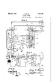
- .Eig 4 is a .diagrammatic ⁇ View .showing the .pi-ping arrangement #and .the Wiring-diagram;
- Fig. 5 is a wiring diagrambf La As'lowmotion .control valve
- Eig. .5a is a ⁇ detail view-.showing .a locking ⁇ .or latching means employed .in .the Acontrol of the .s1ow.m,otion valve Fig. 6-is ⁇ a-,detail elevational vview of thernount- .ing of .a .guide roller;
- Fig .7 is a :sectional View taken .as .along .the line .'l-'l of Fig...6;
- Fig. 8 is a sectional view taken as alongtheline ⁇ E-Bof Fig. 3;
- ythe machine of the .invention comprises a -baseincluding side members I0 and a A.cross -member Il. .
- the -machine Yframe mounted ⁇ on the .base-includes vertical side .members ,I2 .and .a vtop cross mem- :ber --I 3. All .of' the structural members mentionedare I-beams .or channel members of sufcient .dimensionsto givethe vmachine :the de- .lsired rigidity.
- Vertical .side members .I2 Vare channel members .and :are arranged with vtheir .open -sides .facing one another.
- a piston 34 Within cylinder 33 is a piston 34 (see Fig. 4) and a piston rod 35 passes through both ends of the cylinder and is connected with the piston 34. Since the piston rod extends from both sides of the piston the latter has the same exposed area at each of its sides.
- a pipe 36 is provided for supplying and exhausting fluid under pressure to and from the upper end portion of cylinder 33while a similar pipe 31 performs the same functions in connection with the lower end portion of the cylinder.
- the fluid rubber or latex in the tank I'I is slowly circulated therein to prevent the formation of a skin thereon.
- the circulation must not serve to agitate the upper surface of the liCluid in any such manner as to trap air therein.
- the liquid is circulated by a pump generally designated 45 the impeller carrying shaft 45 of which is rotated by a driven belt (not shown) trained over a pulley 41 on the outer end of such shaft.
- the impeller serves to feed the liquid rubber slowly through a pipe 48 into one end of the tank.
- a high baffle plate 49 is disposed so that the liquid enters the tank in a portion thereof which is not to be entered by a form during a dipping operation.
- Baille 49 is raised from the bottom of the tank to leave a passage 5I! and inwardly of the baffle 49 is a second baille 5I reaching from the bottom of the tank to a point below the upper end of baille 45.
- a baffle 53 similar to baffle 5I.
- the space between the baffles 5I and 53 is that into which the forms are dipped during the use of the machine.
- the height which the liquid rubber may reach in the space 55 is indicated by the line 55.
- the level of the liquid rubber into which the forms are dipped is just over the upper edges of the bailles 5I and 53.
- a slight head is built up in the space 55 by the pump 45 and this head is the force used for moving the rubber through the space 5I! and over the baille 5I into the main portion of the tank.
- Necessarily a very slight flow of the liquid rubber results and any excess of the liquid rubber overflows into the space 55 between the baille 53 and the tank end and is removed from the tank through a pipe 5l connected (in a manner not shown) with the intake pipe 4 58 to the pump 45.
- the liquid rubber is kept in constant circulation and the upper or top portion thereof does not have an opportunity to form a skin.
- a control panel mounted on one of the vertical side members i2 of the main frame of the machine.
- this panel comprises a sheet of brass or the like bent to a channel formation as shown best in Fig. 9.
- Starting and stopping switches and 6I are mounted on the upper portion of panel 53.
- speed control switches 62 and 33 On an intermediate portion of the panel are located speed control switches 62 and 33 while on the lower portion of the panel is a reversing switch 54.
- Switch 5E) is a normally open switch while switch 5I is a normally closed switch.
- switch 6I is mounted on the rear side ofpanel 59 as by means of a strap 65 and includes an operating arm 63 carrying a roller 5l at its upper end.
- the panel In alignment with the switch arm 55 the panel is provided with a slot 58 opening through the upper end of the panel. Slidable in and guided by the edges of the slot is a block 69 secured to a rod I9 located at the forward side of the panel and movable through a bearing 1i.
- a screw 'I2 serves to secure the block and rod together in the desired positions of adjustment.
- a coil spring 'I3 has one end secured to the block 69 and has its other end anchored as to the panel 59 and this spring constantly tends to move the block and rod downwardly from the switch arm roller 61. When the block is in a lowered position the switch is free to close.
- Switch 62 comprises upper and lower fixed contacts 'i4 and 'I5 and a movable contact element 'I5 adapted to engage either of said fixed contacts.
- This switch operates with a toggle-like action and when the movable element is forced from engagement with one of the Xed contacts and through a dead center position it is snapped into engagement with the other of the fixed contacts.
- the movable contact element 'i6 is in position engaging one of the fixed contacts at substantially all times.
- Switch G3 (which is in the same housing as the switch 62 and is 'operated by the saine means and at the same times as in Figs. 3 and 9) comprises two fixed contacts 'i8 and 13.
- a movable contact element 8! in said switch is adapted to engage either of said contacts as described in connection with the element 16 of switch 62 and is in fact operated in unison with ⁇ said element 'i6 as will appear.
- Switch 54 is of substantially the same construction as either of the switches 52 and 53 and comprises two fixed contacts SI and 82 and a movable contact element 83 adapted to engage either of the fixed contacts.
- This movable contact element is also operated with a snap action and when moved through a dead center position from engagement with one of the Xed contacts immediately snaps into engagement with the other xed contact.
- the switches 52 and 53 are adapted to be operated by the lower end of a bar 34 vertically movable on the panel 59.
- the switches include an operating rod or button 85 against the outer end of which is located one end portion of an arm 85 pivotally mounted as at 8'! and on its intermediate portion carrying a roller 88 adapted to be engaged by the lower end of the bar 34 as will appear. Movement of bar 85 relative to the panel 59 is guided as the panel is provided with a slot 89 opening through its lower ⁇ end and the bar is movable in said slot as suggested in Fig. 9.
- a coil spring 90 having its upper end anchored to the panel as at 9
- a scale 92 is marked off on the panel or on a separate plate secured to the panel as may be desired. Movable over this scale and carried by the bar 84 is a pointer 93 secured to the bar as by means of a screw 94 having a relatively long exposed shank portion 95.
- Reversing switch 84 includes a crescent shaped operating member 96 the free ends of the arms 91 and 98 of which are disposed above and below, respectively, a lug 99 on a block
- Switch 64 is located at the rear of panel 59 but the latter is provided with a slot
- 08 adjustably secures the block on the rod.
- 8 projects over the panel 59 in a manner to bring about operation of the switches. At the end of a dipping cycle said arm engages the lower end of rod and moves the same upwardly against the action of spring 13 opening the switch 5
- a constantly operating hydraulic pump taking liquid from a supply tank
- the discharge of the pump is through a pipe
- the pipe H4 discharges into a pair of branches
- Branches H1 and H8 discharge into a pipe
- Said reversing valve supplies liquid under pressure to and provides for exhausting of liquid from the pipes 39 and 31 above mentioned and which are connected with the upper and lower portions of the cylinder.
- are manually adjusted to permit of a maximum rate of flow through the respective branches H1 and H8 of the pipe line to valve
- 20 is. called a fast valve as it opens and closes fast and is in the fast line to distributing valve
- 22 is herein identified as a slow valve since it is in the slow line to valve
- 24l are electrically controlled. To simplify the drawing the various circuits are shown as grounded.
- Current supply line from any suitable source includes wires
- switch 60 is closed to start the machine a circuit is closed through the contacts 14 of switch 62 and through a wire
- 05 At a predetermined point in the upward movement -of the carrier the bar
- the switch element l5 As the switch element l5 is thus moved ⁇ it leaves contact 'l5 opening the circuit to the slow valve
- the rod l0 By loosening screw l2 the rod l0 is made free for adjustment through the block 69 and the location ,of the lower end of the rod determines the point at which the carrier
- the point of stoppage of the machine may be determined by locating the loweiend .of the rod with reference to the graduations
- Fig. diagrammatically illustrates the immediate control of the slow valve
- 45 respectively drives a cam.
- Fixed to the bar
- 51 controls a locking bar
- the locking bar is pivotally mounted as in Fig. 5a and includes a bevelled portion 66 which is pulled into a notch in the bar
- the solenoid is connected with the latch V
- has a handle
- ' is open its handle being held in the full line position by the finger
- 55 a circuit is completed to motor
- the cam turns it shifts the bar
- 43 continues to operate and nally the nger
- 53 is functioning the valve
- 22 is returned to normal condition ready for use when line
- 25 is balanced and no additional fluid under pressure is being fed the cylinder 33 and the carrier is temporarily stationary.
- This described operation takes place just as the forms are leaving the rubber contents of the receptacle Il and gives the forms a chance to drain While yet approximately in contact with the contents of the tank.
- closes the circuit to the solenoid
- a carrier mounted by said frame for guided movements toward and from the contents of the receptacle, means for mounting forms on said carrier, hydraulic means for moving said carrier in the frame to carry the forms into and out of the contents of the receptacle, said hydraulic means including a piston and cylinder construction, a source of liquid under pressure, valve means for distributing such liquid to the cylinder at opposite sides of the piston to lower and raise the carrier, a pair of valves comprising a fast and a slow valve controlling the passage of said liquid under pressure to the.
- said fast valve is open and said slow valve is closed during movements of the forms toward and from the contents of the receptacle and said fast valve is closed and said slow valve is open during movement of the forms into and out of and while in the said contents of the receptacle
- said means for opening said slow valve including a cam whereby the rate 'of opening of said slow valve is controlled by the contour of said cam.
- a piston and cylinder construction means movable by said piston to projected and retracted positions, a source of liquid under pressure, valve means for distributing such liquid to the cylinder at opposite sides of the piston to project and retract said means, fast and slow valves controlling the rate at which said liquid is supplied to the cylinder, means controlling said valves whereby said liquid is supplied at a higher rate during initial movement of the rst mentioned means toward and its nal movement from projected position than during iinal movement of said first mentioned means toward projected position and its initial movement from projected position whereby said first mentioned means is moved at a faster rate during the first mentioned times than during the latter mentioned times, said means controlling said valves comprising electrical means, switch means controlling said electrical means, means whereby on its movements to and from projected position the means movable by the piston trips said switch means to close said fast valve and open said slow valve as said means completes the initial part of its movement toward projected position and to close said slow valve and open said fast valve as the said means movable by the piston completes the initial part
- a hydraulic means a piston and cylinder construction, a carrier connected to be moved by said piston, a source of liquid under pressure, valve means for distributing such liquid to the cylinder at opposite sides of the piston to raise and lower said carrier, automatic means controlling said valve means whereby the liquid under pressure is supplied to the respective sides of the piston at predetermined times, a line for supplying said liquid under pressure to said valve means for distribution thereby to said piston, a second line for supplying said liquid under pressure to said valve means for distribution thereby to said piston, independently adjustable manually operable valves located one in each of said lines and controlling the maximum rate at which such liquid under pressure may be supplied the valve means by the respective lines, a quick opening and closingI valve in the line with one of said manually operated valves, and a slow opening valve in the line with the other of said manually operable valves.
- a piston and cylinder construction a carrier movable by said piston, a source of liquid under pressure, valve means for distributing such liquid to the cylinder at opposite sides of said piston to raise and lower the carrier, electrical means controlling the position of said valve means and thus the side of the piston to which said liquid is supplied, a normally open manually operable starting switch for controlling said electrical means to have said valve direct said liquid to a side of the piston to cause movement of the carrier downwardly, a normally closed stopping switch connected in parallel with said starting switch and located to be opened by said carrier at the end of its return movement'and to be held open by said carrier until the latter starts its next downward movement on closing of the starting switch, a reversing switch connecd in series caemos with Ysaiid starting and stopping switches and operable by the carrier on'- lts downward movel 'ment from one circuit closing vposition to another to Icause said electrical means to 'reverse 'said valve and supply said liquidunder pressure to the 'other side
- a receptacle a frame, a carrier mounted by said frame for guided movements toward and from the contents of the receptacle, means for mounting forms on said carrier, hydraulic means yfor moving said carrier in the frame to carry the forms into and out oi the contents of the receptacle, said hydraulic 'means including -apiston and cylinder construction, Ia source of ⁇ liquid under pressure, valve Linean's for distributing such liquid to the cylinder' at' opposite sides of the 'piston to lower 'and raise the carri-er, a pair of lines for supplying liquid under pressure to the distributing valve, a l'fast/valve in one of said lines, a slow valve in the other of said lines, independently adjustable manually operable valves located one in each of said lines for controlling the maximum rate at which uid under pressure may be supplied the distributing valve by the respective lines.
- a receptacle a frame, a carrier mounted by said frame for guided movements toward and from the contents of the receptacle, means for mounting forms on said carrier, hydraulic means for moving said carrier in the frame to carry the forms into and out of the contents of the receptacle, said hydraulic means including a piston and cylinder construction, a source of liquid under pressure, valve means for distributing such liquid to the cylinder at opposite sides of the piston to lower and raise the carrier,v a pair of lines for supplying liquid under pressure to the distributing valve, a fast valve in one of said lines, a slow valve in the other of said lines, independently adjustable manually operable valves located one in each of said lines for controlling the maximum rate at which uid under pressure may be supplied the distributing valve by the respective lines, and said means for opening said slow valve including a cam whereby the rate of opening of said valve is controlled by the contour of said cam.
- a hydraulic means a piston and cylinder construction, 'a carrier connected to be moved by said piston, a source of liquid under pressure, valve means for distributing such liquid to the cylinder atopposite sides of the piston to ⁇ raise and lower said carrier, automatic means controlling said valve means whereby the liquid under pressure is supplied to the respective sides of the piston at predetermined times, a line for supplying said liquid under pressure to said valve means for distribution thereby to said piston, a second line for supplying said liquid under pressure to said valve means for distribution y thereby to said piston, independently adjustable 15 manuaiiy operable valves located one in each of said lines and controlling the maximum rate at which such liquid under pressure may be supplied the valve means by the respective lines, a quick opening and closing Valve in the line with one of said manually operated valves, a slow opening Valve in the line with the other of said manually operable Valves, and a cam for opening said slow opening Valve whereby the rate of opening thereof is controlled by the contour of said cam.
Description
- March 2, 1948. 1 E; MAQUAT 2,437,109
- DIP'PING MACHINE Filed FeB. 25', `1941 4 sheets-sheet 1 March 2,1948. E, MAQUAT 2,437,109
DIPPING MACHINE Filed Feb. 25, 1941 4 SheeS-Shee';l 2 l Marh 2', 194s.
L. E. MAQUAT 2,437,109
DIPPING MACHINE Fi1ed`Feb. 25, 1941 4 Sheets-Sheet 3 March 2, 194:5.l E, M'AUT 2,437,109
DIPF ING MACHINE Filed Feb. 25, 1941 4 Sheets-Sheet 4 Y r WAL-mil Annul 'www 199% r11/fa AA IAMMM Liagd Mafu Patented Mar. 2, 1948 reo s TATES PAT-ENT v*orrlzciz DIPPING MACHINE Lloyd .E. Magnat, Easton, Conn., assigner to'The .'Bla'ck Rock Manufacturing Company, Bridgeport, Conn., a vcorporation of Connecticut Application February 25, 1941,-Serial No. 380,452
This invention .relates to new :andnsefu'l improvements in. rubber dippingmachines and yhas .particular relation .to anautomaticmachine having adenitecycle .of operation and .adapted for the-making'ofdinped .rubber articles made from any .solution ofrubberor rubber-.like material or of any.rubber'or-.rubber-like latex.
The objects .and -advantages of the .invention will become apparent .from .a consideration of Atl'xeiollowing `detailed .descriptiontaken in connection with .the :accompanying drawings -Whereina-satisfactory embodiment of the. invention .is shown. .'However, 4itis .tol-beunderstood that `the .invention .isnot :limited `to :the .details disclosed but includes all such variations and modifications as .fall within the .spiritof .the Y.invention and the .scope -of the .appended claims.
Inthe drawings- .Fig.1f-is.a.front elevational .view of .the ;ma chine. of the invention;
Fig. `2..is .a side elevational view thereof.;
Fig ..3 .is .an enlarged ...front elevational .view jof .--t-he .control .panel .of the machine;
.Eig 4 is a .diagrammatic `View .showing the .pi-ping arrangement #and .the Wiring-diagram;
Fig. 5 is a wiring diagrambf La As'lowmotion .control valve;
Eig. .5a ,is a `detail view-.showing .a locking `.or latching means employed .in .the Acontrol of the .s1ow.m,otion valve Fig. 6-is`a-,detail elevational vview of thernount- .ing of .a .guide roller;
Fig .7 is a :sectional View taken .as .along .the line .'l-'l of Fig...6;
Fig. 8 is a sectional view taken as alongtheline `E-Bof Fig. 3;
.Eigvfl-O .fis afsectional .vieu/.taken .as along the lline llll0 .of Fig. 3; `and fFig. 11 visa view 'takenas .looking .from the left inflig. .10.
.Referring in :detail .to the drawings ythe machine of the .invention comprises a -baseincluding side members I0 and a A.cross -member Il. .The -machine Yframe mounted `on the .base-includes vertical side .members ,I2 .and .a vtop cross mem- :ber --I=3. All .of' the structural members mentionedare I-beams .or channel members of sufcient .dimensionsto givethe vmachine :the de- .lsired rigidity. Vertical .side members .I2 Vare channel members .and :are arranged with vtheir .open -sides .facing one another. :Within said channelmembersare mounted verticalguides I4 .and `I5. respectively .secured .in .place as .by .bolts I'S and .eachfhaving a .V-shaped .channel k therein receiving `and rforming runways'forrollers as will appear.
.Supported on .the cross .member 'lil of the machine baseis a tank il containing arubber solution orcontaining latex as -the case may be.
v-Vertioally movable in .the machine v4frame .is .a carriergenerally Vdesignated 13 and comprising .tormjboardsl' on which are mounted any de- .,sirediorins I4.
.Passing through an opposite pair of the .chan- .nel members `of .therack I2.2 .are ,the longer .arms
.of clampsf. At the upper vsijdexjifthe rackthe .,-ends ofthesearms .arepivotally connected .with
.cam-.levers .25 .and it Ywill 'be clear, especially from Fig. l, .that .the vcam-.levers ,are movable .frompositions wherein .their -lovverends .21 .are clamping the -iormlboards `'23 .against ,the undere .sideof .the rack .topositions Whereinsaidends .arelloweredwith.respect 'to .the Vsaid sides o'f the rack. Whenthe .cam-flevers'have j been manually rocked to lower the form boards the latter may `be .removedfrom the .rac-k .for .placement in a .drieras isusuallin .the art.
;Fixedfto...one ofthe shortshafts yITM is a .crank .23 adapted .to .be .manually manipulated torock @the rrack,ithrinighan.arc of degrees whereby .to .dispose the -form boards .at the Aupper side -of .the-rack. The-.purpose .of .thisswinging yof lthe v.rack will later `be described.
.'Mounted `.on theshait with .the .crank I.ijs a .ratchet disc .29..and mounted on .a bar am by the .next notch of the .ratchetdisc and secures .the parts .in their new positions. For .thepres- .entpurpose Vthe .ratchet-disc has but two .notches .arranged 180 degrees apart.
[Vertical movement y.isimparted to .the .carrier .|.8 .bylhydrauliomeans v,luclrfmeans as .herein .disclosed includes a cylinder 3'3.mountedon the .top cross .bar .or .member r.lf3-.of .the machine frame.
ed into tapped openings in the plates.
Within cylinder 33 is a piston 34 (see Fig. 4) and a piston rod 35 passes through both ends of the cylinder and is connected with the piston 34. Since the piston rod extends from both sides of the piston the latter has the same exposed area at each of its sides. A pipe 36 is provided for supplying and exhausting fluid under pressure to and from the upper end portion of cylinder 33while a similar pipe 31 performs the same functions in connection with the lower end portion of the cylinder.
Mounted on the carrier I8 (see Fig. 1) and located at the outer sides of the rods 20 are short vertically disposed sections 4i] of I-beams. These parts serve to mount small rollers 4I having V- shaped edge portions received or operating in the channels of the vertical guides I4 and I5 above described. Each of these rollers is mounted on the outer end of a bar 42. Plates 43 are welded to the I-beans i] (see Figs, '7 and 8) and the bars 42 are secured to said plates as through the use of bolts 44 passing through the bars and thread- To provide for proper adjustment of the rollers with relation to the guideways or tracks I4 and I5 the bars are slotted at 44a for the passage of the bolts 44. Owing to the'use of the pair of vertically spaced rollers at each side of the carrier should the top bar I9 of the carrier spring slightly under load there will be no binding of the rollers in the guideways such as would occur if elongated guide members were engaged in the guideways.
The fluid rubber or latex in the tank I'I is slowly circulated therein to prevent the formation of a skin thereon. However the circulation must not serve to agitate the upper surface of the liCluid in any such manner as to trap air therein. As herein disclosed the liquid is circulated by a pump generally designated 45 the impeller carrying shaft 45 of which is rotated by a driven belt (not shown) trained over a pulley 41 on the outer end of such shaft. The impeller serves to feed the liquid rubber slowly through a pipe 48 into one end of the tank. At such end of the tank is a high baffle plate 49 is disposed so that the liquid enters the tank in a portion thereof which is not to be entered by a form during a dipping operation.
The level of the liquid rubber into which the forms are dipped is just over the upper edges of the bailles 5I and 53. Thus a slight head is built up in the space 55 by the pump 45 and this head is the force used for moving the rubber through the space 5I! and over the baille 5I into the main portion of the tank. Necessarily a very slight flow of the liquid rubber results and any excess of the liquid rubber overflows into the space 55 between the baille 53 and the tank end and is removed from the tank through a pipe 5l connected (in a manner not shown) with the intake pipe 4 58 to the pump 45. Thus the liquid rubber is kept in constant circulation and the upper or top portion thereof does not have an opportunity to form a skin.
Mounted on one of the vertical side members i2 of the main frame of the machine is a control panel generally designated 59. Preferably this panel comprises a sheet of brass or the like bent to a channel formation as shown best in Fig. 9. Starting and stopping switches and 6I, respectively, are mounted on the upper portion of panel 53. On an intermediate portion of the panel are located speed control switches 62 and 33 while on the lower portion of the panel is a reversing switch 54. Switch 5E) is a normally open switch while switch 5I is a normally closed switch.
As shown in detail in Fig. 3 switch 6I is mounted on the rear side ofpanel 59 as by means of a strap 65 and includes an operating arm 63 carrying a roller 5l at its upper end. In alignment with the switch arm 55 the panel is provided with a slot 58 opening through the upper end of the panel. Slidable in and guided by the edges of the slot is a block 69 secured to a rod I9 located at the forward side of the panel and movable through a bearing 1i. A screw 'I2 serves to secure the block and rod together in the desired positions of adjustment. A coil spring 'I3 has one end secured to the block 69 and has its other end anchored as to the panel 59 and this spring constantly tends to move the block and rod downwardly from the switch arm roller 61. When the block is in a lowered position the switch is free to close.
Switch G3 (which is in the same housing as the switch 62 and is 'operated by the saine means and at the same times as in Figs. 3 and 9) comprises two fixed contacts 'i8 and 13. A movable contact element 8!! in said switch is adapted to engage either of said contacts as described in connection with the element 16 of switch 62 and is in fact operated in unison with` said element 'i6 as will appear.
As shown in Fig. 3 the switches 52 and 53 are adapted to be operated by the lower end of a bar 34 vertically movable on the panel 59. To this end the switches include an operating rod or button 85 against the outer end of which is located one end portion of an arm 85 pivotally mounted as at 8'! and on its intermediate portion carrying a roller 88 adapted to be engaged by the lower end of the bar 34 as will appear. Movement of bar 85 relative to the panel 59 is guided as the panel is provided with a slot 89 opening through its lower` end and the bar is movable in said slot as suggested in Fig. 9.
Attached to the upper end of the bar 84 is a coil spring 90 having its upper end anchored to the panel as at 9| and it will be clear that this spring is constantly tending to move the bar 84 upwardly and that upward movement of the bar is limited by the upper end of the slot 89. A scale 92 is marked off on the panel or on a separate plate secured to the panel as may be desired. Movable over this scale and carried by the bar 84 is a pointer 93 secured to the bar as by means of a screw 94 having a relatively long exposed shank portion 95.
It is to be understood that as the bar 89 is moved downwardly its lower end engages the roller 88 and shifts the movable contact elements of the switches 62 and 63 from engagement with the upper contacts of said switches into engagement with their lower contacts. Then as the spring 90 moves the bar upwardly releasing the roller 88 the switches return to normal and the movable elements of the switches return to positions engaging the upper contacts.
As pointer 93 is secured to the bar 84 by the screw 94 it will be understood that the pointer may be adjusted along the bar and the purpose of this arrangement will appear. During downward movement of bar 84 the latter rides against the roller 88 maintaining the switches in the positions to which they have been moved as when the upward movement of the bar, under the action of the coil spring, carries the bar above the roller 88 the switches return to normal.
Reversing switch 84 includes a crescent shaped operating member 96 the free ends of the arms 91 and 98 of which are disposed above and below, respectively, a lug 99 on a block |00 adjustably secured on a rod located at the forward side of the panel 59 and vertically movable in bearings |02. Switch 64 is located at the rear of panel 59 but the latter is provided with a slot |03 opening through its lower end and into which slot the lug 99 projects for cooperation with the switch arms 91 and 98 and also to guide the movements of the block |00 and rod |0|. A screw or other suitable means |08 adjustably secures the block on the rod.
With the arrangement described it will be understood that on the lug 99 being moved downwardly (from the position of Fig. 3) it will .engage the switch arm 98 and reverse the movable Contact element of the switch 64. Similarly on the lug 99 being thereafter moved upwardly it will engage the switch arm 91 and restore the .switch to normal. This is true since the switch is a snap switch and when the arm 98 is engaged and moved to carry the movable contact element of switch 64 through a dead center position the arm 91 also moves and then is carried to a position over the lug 99 when the switch snaps over to close a circuit through the lower of its fixed contacts.
A rigid arm |05 movable with the carrier |8 projects over the panel 59 in a manner to bring about operation of the switches. At the end of a dipping cycle said arm engages the lower end of rod and moves the same upwardly against the action of spring 13 opening the switch 5| and bringing the machine to a stop.
To start the machine the operator manipulates a handle |98 to close the normally open switch 90 and at the same time the required movement of the handle results in an upward movement being given a rod V|01 extending vertically along the panel. At its lower end this rod is threaded or otherwise secured in a block |08 carrying a short bar |09 xed in the block |00 above mentioned. Thus as the handle isk manipulated to close the starting switch t0 the block |00 is moved upwardly whereby its lug 99 engages the upper switch arm 91 and returns. the switch 64 to normal.
Referring now to `diagrammatic Fig. 4 at is indicated a constantly operating hydraulic pump taking liquid from a supply tank ||2 through a pipe ||3. The discharge of the pump is through a pipe ||l| having a pressure regulating and relief valve ||5 therein and which serves to control the pressure at which the liquid is delivered to the cylinder 33 by by-passing excessive liquid back to the tank ||2 through pipe H6.
Beyond the relief valve 5 the pipe H4 discharges into a pair of branches ||1 and ||8 in the former of which is located a manually adjustable needle valve I |9 and a fast valve |20 while in the latter is located a manually adjustablev needle valve |2| and a slow valve |22. Branches H1 and H8 discharge into a pipe |23 connected with a four-way reversing valve |24. Said reversing valve supplies liquid under pressure to and provides for exhausting of liquid from the pipes 39 and 31 above mentioned and which are connected with the upper and lower portions of the cylinder.
Needle valves ||9 and |2| are manually adjusted to permit of a maximum rate of flow through the respective branches H1 and H8 of the pipe line to valve |24. The adjustments made will depend -on any particular job to be performed by the machine. Usually valve A|2| is. more nearly closed than is valve ||9 whereby a more restricted flow is possible through line H8 than through line |.|1 and line H8 may therefore be referred to as a slow line..
Valve |20 is. called a fast valve as it opens and closes fast and is in the fast line to distributing valve |24. While the particularly ccnstruction of valve |20 is not important it may be of the construction of the valve shown on page 13 (May 1, 1939) of the Industrial Control Handbook, `published by General Electric Company, of Schenectady, New York. Valve |22 is herein identified as a slow valve since it is in the slow line to valve |24 and is opened slowly by the cam |49 as hereinafter more fully set forth.
Valves |20, |22 and |24l are electrically controlled. To simplify the drawing the various circuits are shown as grounded. Current supply line from any suitable source includes wires |25 and |28 in which are located a main switch |21. Starting and stopping switches B9 and 6| are connected in parallel in line |25 and the movable contact elements of switches 92 and 84 are connected with such line by wires |28 and |29. Thus when switch 60 is closed to start the machine a circuit is closed through the contacts 14 of switch 62 and through a wire |30 to the fast valve |20 energizing the solenoid thereof and opening such valve. At the same time through the upper contact 8| of switch 64 a circuit is completed to the solenoid |3| of the valve |28 through wire |32 whereby the valve is placed in condition to supply liquid under pressure to the pipe 39 and cylinder 33 and to place the pipe 31 in communication with a return pipe |33.
As the liquid under pressure Vmoves the carrier i downwardly bar |65 releases rod 'l0 and the coil spring 73 moves the rod and the block 60 downwardly permitting the normally closed switch tl to close. Now the starting switch may be released. The carrier continues downwardly and at the desired point, depending on the adjustment of the pointer 53 on the rod 84, it engages the shank S of the screw 913 and forces the rod 31 downwardly engaging the roller 88 and reversing the switch 62 so that its movable element 'l5 is shifted from engagement with the upper fixed contact le into engagement with the lower i-lxed contact l5.
This brings about an opening of the circuit to the fast valve l2@ and a closing, through wire i3d, of a circuit to the slow valve |22. Valve iiiil is thus closed and valve |22 is opened as will later appear. The tripping of switch 02 results in tripping of switch Si@ so that its movable contact 80 is shifted from engagement with fixed contact 'E8 into engagement with xed contact 79. However, at this time switch 03 is not energized.
Continued downward movement of the carrier results in bar |535 being brought into engagement with the upper end of rod li and movement of the same and the lug Q8 downwardly causing the latter to engage the switch arm 98 and bring about a tripping of the switch Si@ shifting its element S3 from engagement with contact 8| into engagement with contact 82. This results in an opening of the circuit to the reversing valve solenoid |3| and the closing of a circuit through a wire |35 to the movable element 80 of switch E55 and which element is now in engagement with contact 'l0 of such switch. 4.
Thus while the circuit to the solenoid |3| of the reversing and distributing valve |25 is now open, a circuit to the solenoid E35 of such valve is closed through wire ii'i from switch contact le and a ire |38 connecting wire l'l with the solenoid ltd. Connected in the wire i3? is a timer device its which functions to keep open the circuit to solenoid E35 for a predetermined length of time for a purpose to be set forth. f
When the solenoid |35 is energized it attracts the armature or core attached to lever H50 and rocks the latter to position the valve H24 for the supplying of liquid under pressure to the upper end portion of cylinder 33 and for exhausting of liquid from the lower end of the cylinder so that when the solenoid itl is energized the carrier is being moved downwardly. At the end of the downward movement of the carrier the bar |05 tripping element S3 from contact Si into engage ment with contact 82 opens the circuit to solenoid ll and attempts to close a circuit to solenoid |36. When the latter is energized the valve i213 is reversed and supplies liquid under pressure to the lower end portion of cylinder 33 and permits of the exhausting of liquid from the upper end portion of such cylinder. Now the piston ifi will be moved upwardly in the cylinder and rod S5 being connected with carrier i8 the latter will be moved upwardly in the main frame of the machine.
At a predetermined point in the upward movement -of the carrier the bar |05 will be moved from the bar es or at least from engagement with the shank 95 of the screw Eli/l and the coil spring 00 will raise such bar and the switches 62 and 63 will be reversed or shifted back to normal condition. As the switch element l5 is thus moved `it leaves contact 'l5 opening the circuit to the slow valve |22 and it engages contact I4 closing the circuit through wire |30 to the fast valve |20.
When the switch 63 is reversed at this time its element is moved from engagement with contact 'lil into engagement with contact 18 plac-Y ing the same, through a wire |3'ia in circuit with wire E38 connected with the reversing valve solenoid |35. A timer lill in the line |3'ia, keeps the circuit open through such wire for a predetermined time for a purpose to be explained. After such delay as is experienced due to the presence of the timer |4l| the upward movement of the carrier is resumed at a fast rate valve |20 now being open. As the rack reaches the limit of its upward movement bar 05 engages the lower end of rod 'lil (see Fig. 8) and moves such rod upwardly carrying block 69 into engagement with roller El and bringing about opening of the normally closed stopping switch 6|.
Thus since the switch 50 is open the machine is brought to a stop, sclenoids |3| and |36 each being deenergized the valve l2@ is balanced and the whole machine :is at rest. The operator now moves the crank 23 and reverses the rack 22 to dispose the 1atter with the form boards at its upper side. The form boards are removed and placed in a drier or the like and new boards mounting forms are placed on the rack, the latter is reversed by using the crank 2B and the handle S is operated to close the starting switch etV and as soon as the bar |05 is carried downwardly away from the bar lli such handle may be released and the machine will then automatically go through its predetermined cycle of operation.
In this connection it is noted that when the operator shifts the handle |06 to close switch t he moves the rod i0? and through the cross bar liiS raises the rod l0! with the block |90 and the lug 09 and the latter trips the switch 611 to dispose its movable contact element in the position of Fig. 4 wherein the circuit is closed to the down solenoid 53| ofthe reversing and distributing` valve |24.
By loosening screw l2 the rod l0 is made free for adjustment through the block 69 and the location ,of the lower end of the rod determines the point at which the carrier |8 will stop at the end of a cycle of the machines operation. When making an adjustment of the rod the point of stoppage of the machine may be determined by locating the loweiend .of the rod with reference to the graduations |42 which may be on the panel 55 or may be on a separate plate attached to such panel.
As engagement of the bar |05 with the shank 05 of'screw gli determines the movements of bar or rod @it adjustment oi such screw in relation to the length of the rod will bring about a change in the timing of the machine. When the screw is loosened it is adjusted along with the pointer S3 and by reading the latter in connection wit the marks 92 the times at which the fast valve |20 and the slow valve H22 are placed in and out of Aoperation may be controlled.
Since switch Se brings about a reversal of the direction ci movement of the carrier l0 it will be seen that adjustment of the rod lill vertically will bring about a change in the depth to which the forms are moved into the contents of the receptacle il. Rod |0l may be adjusted through the block lili! `on loosening of the screw |04 and if it is adjusted downwardly the forms will be carried deeper into the tank Il while if it is adlusted upwardly the dip will not be so deep. Thus 9 thef rod is adjustedaccording to the length of the articles being manufactured.
Fig. diagrammatically illustrates the immediate control of the slow valve |22. In such iigure an electric motor |43 through a worm and worm gear |44 and |45 respectively, drives a cam. |46 against which rides, except when the valve |22 is open, a bar |41 longitudinally movable through any suitable support as through a mounting |45. A coil spring |40 about a portion of bar I 41 and bearing at one end against the support |48 and at its other end against a collar |50 fixed to the bar, normally tends to keep the bar in engagement with the cam |45 and when the bar is not otherwise held does keep'it against the cam.
Fixed to the bar |41 is a block |5| having a notch |52 receiving the free lend portion of the operating lever |53 of the valve |22. Also fixed to said bar is a block |54 adapted to engage and move the handle |55 of a switch |56 as will appear. A solenoid |51 controls a locking bar |58 and a coil spring |59 connects said locking bar with the core of the solenoid. The locking bar is pivotally mounted as in Fig. 5a and includes a bevelled portion 66 which is pulled into a notch in the bar |41 when the latter is in the extreme position in which it is shownin Fig. 5 `and the solenoid is energized. y
The solenoid is connected with the latch V|50 through the spring |59 in order that the solenoid core may .seat home before the latch actually reaches the bottom of the notch in bar |41. Owing to the bevel of part |60 the spring |49 may move the locking bar |58 out of the `notch in the bar |41 when the solenoid is deenergized although if desired a counterbalancing spring may be attached to the locking bar.
When the solenoid |51 is deenergized the coil spring |49 urging the bar |41 to its normal position .causes the sides of the notch to act on the bevelled sides of part |60 of the locking part or `bar |58 whereby the latter is cammed out .of said notch and then the spring |49 returns the parts to normal positions. A second switch |6| has a handle |62 disposed for operation by a ngerlike member |63 carried by the cam 146. The latter is rotated in the direction indicated by the arrow |64 and the motor |43 includes a variable speed drive for the shaft '|65 through which the worm gear |45 is driven.
Prior to the tripping of the switch 62 on the downward Vmovement of carrier I6 and after tripping of said switch during upward movement of the carrier the wire |34 is deenergized. At these times the valve |22 is completely closed and the switches |56 and |6| are both normally closed switches and are closed. Now on venergizing of wire |34 solenoid |`51 is energized and tries to move the lock bar |53 downwardly to a position locking the bar' |41 lagainst movement by the coil spring |49. However, the notch in the bar |41 is not in alignment with the locking bar at this time as such bar |41 is in the dotted line position of Fig. 5 and against the low point of cam |46.
At this time switch |6| 'is open its handle being held in the full line position by the finger |63 on the cam v|46 ibut switch |56 is closed its rhandle being in the dotted line position. Thus through switch |55 a circuit is completed to motor |43 through wires |65 and |66 and the motor is operating moving the cam |46. As the cam turns it shifts the bar |41 toward the'left (as viewed in Fig. -5) moving the block |51 and |55 and thus brings about opening of the switch |56. However, the circuit to the motor |43 is maintained since the finger |63 has now passed the switch handle |62 and the switch |6| returns to its normal closed condition maintaining the circuit to the motor as its wires |61 and |68 connect it in parallel with the switch |56. When the high point of cam |46 is reached the solenoid |51 being energized its locking bar |50 is drawn downwardly moving the locking bevelled portion into the notch in the bar |41 and securing the latter in the full line position shown.
The motor |43 continues to operate and nally the nger |63 engages the switch handle |62 and moves the same opening the switch |6| whereupon the motor circuit is broken and the latter stops. As the locking bar |53 is functioning the valve |22 is maintained opened but when the line |34 is next deenergized on revesal of the switch element 16 by the bar |05 during upward movement of the carrier |3, the coil spring |49 acts as above described shifting the bar |41 back to the dotted line position of Fig. 5. This results in closing of the valve |22 and closing of the switch |56 as well as deenergizing of the motor |43. Thus the means controlling valve |22 is returned to normal condition ready for use when line |34 is again energized.
.Assuming rack |8 to be loaded with forms the operator closes switch 60 and thus completes circuits to the fast valve |20 and the down solenoid |3|. At this time Valves ||9 and |2| have been manually set and control the maximum Ypassage of liquid under pressure to the cylinder 33. The carrier starts downwardly .rather rapidly and moves at the rate established by the setting of valve ||9 until the bar |05 reverses the switch 62 deenergizing the solenoid of valve |20 and energizing the motor |43 of the slow valve |22. This voccurs just as the forms 24 (or other forms) on the carrier are `about to enter the rubber in tank |1 and is conthe rate of movement of the forms into the rubber depends on the configuration of the cam |46 and that the rate of movement of the forms in the rubber depends on the setting of the valve |2| and the extent to which the valve |22 is opened by the cam |46. When the "iast valve |20 is closed the carrier is stopped and then is started with a gradually accelerating movement as the cam |46 slowly opens the valve |22 and because of the setting of the needle valve |2| the carrier is not moved as fast when the valve |22 is fully opened as when the valve |20 is fully open. At the end of the down stroke, which depends on the setting of the rod 0| switch 64 is reversed opening the circuit to the down solenoid |3| and closing the circuit through wires |31|38 and the timer |39. The setting of the timer is predetermined and controls a pause of the carrier I8 at the lower limit ll of its stroke so that rubber may collect or coat onto the forms.
When the timer closes, the circuit to the up solenoid |36 is completed and the circuit io the slow valve remains closed so that the carrier and its load move slowly upwardly raising the forms in the rubber. When the bar trips the switches 62 and 63 during upward movement of the carrier the circuit to the slow valve |22 is interrupted and the circuit to the "fast valve |29 is again completed. ,Howeven at this time the circuit to the up solenoid |55 is through the lines |3`|a|38 and is interrupted by the timer HH.
Thus the valve |25 is balanced and no additional fluid under pressure is being fed the cylinder 33 and the carrier is temporarily stationary. This described operation takes place just as the forms are leaving the rubber contents of the receptacle Il and gives the forms a chance to drain While yet approximately in contact with the contents of the tank. When the timer |l| closes the circuit to the solenoid |35 the fast valve |2il is open and the carrier i8 moves upwardly rather rapidly as compared with its rate of movement during the times the forms were in the rubber.
Atthe upper end vof the stroke the bar i935 opens switch 6| bringing the machine to rest. It will be understood that the proper adjustments are made for any particular job so as to have the carrier travel the minimum distance required for that particular job and that the timers |39 and Ml are adjusted or set to represent therninimum pauses to prevent loss of time and that for the same reason the slow valve |22 is used as little aspossible and the fast valve |20 as much as possible and yet have the machine produce the desired quality of product. The conguration of the cam |46 is determined by the particular job to be performed. Valves ||9 and |2| having been manually adjusted for a job they remain fixed until another job is to be undertaken. The adjustments of these valves determines the maximum rates of movements of the forms when the fast and slow valves are open.
Having thus set forth the nature of my invention,'what I claim is:
1. In a dipping machine, a receptacle, a frame,
a carrier mounted by said frame for guided movements toward and from the contents of the receptacle, means for mounting forms on said carrier, hydraulic means for moving said carrier in the frame to carry the forms into and out of the contents of the receptacle, said hydraulic means including a piston and cylinder construction, a source of liquid under pressure, valve means for distributing such liquid to the cylinder at opposite sides of the piston to lower and raise the carrier, a pair of valves comprising a fast and a slow valve controlling the passage of said liquid under pressure to the. distributing valve, means whereby said fast valve is open and said slow valve is closed during movements of the forms toward and from the contents of the receptacle and said fast valve is closed and said slow valve is open during movement of the forms into and out of and while in the said contents of the receptacle, and said means for opening said slow valve including a cam whereby the rate 'of opening of said slow valve is controlled by the contour of said cam.
2. In a hydraulic system, a piston and cylinder construction, means movable by said piston to projected and retracted positions, a source of liquid under pressure, valve means for distributing such liquid to the cylinder at opposite sides of the piston to project and retract said means, fast and slow valves controlling the rate at which said liquid is supplied to the cylinder, means controlling said valves whereby said liquid is supplied at a higher rate during initial movement of the rst mentioned means toward and its nal movement from projected position than during iinal movement of said first mentioned means toward projected position and its initial movement from projected position whereby said first mentioned means is moved at a faster rate during the first mentioned times than during the latter mentioned times, said means controlling said valves comprising electrical means, switch means controlling said electrical means, means whereby on its movements to and from projected position the means movable by the piston trips said switch means to close said fast valve and open said slow valve as said means completes the initial part of its movement toward projected position and to close said slow valve and open said fast valve as the said means movable by the piston completes the initial part of its movement toward retracted position, said switch means including adjustable means that may be tripped by the means movable by the piston from the desired position of the latter to vary the relation between the initial and nal positions of its movements, and said means for opening said slow valve including a cam whereby the rate of opening of said valve is controlled by the contour of said cam.
3. In a hydraulic means, a piston and cylinder construction, a carrier connected to be moved by said piston, a source of liquid under pressure, valve means for distributing such liquid to the cylinder at opposite sides of the piston to raise and lower said carrier, automatic means controlling said valve means whereby the liquid under pressure is supplied to the respective sides of the piston at predetermined times, a line for supplying said liquid under pressure to said valve means for distribution thereby to said piston, a second line for supplying said liquid under pressure to said valve means for distribution thereby to said piston, independently adjustable manually operable valves located one in each of said lines and controlling the maximum rate at which such liquid under pressure may be supplied the valve means by the respective lines, a quick opening and closingI valve in the line with one of said manually operated valves, and a slow opening valve in the line with the other of said manually operable valves.
4. In a hydraulic system, a piston and cylinder construction, a carrier movable by said piston, a source of liquid under pressure, valve means for distributing such liquid to the cylinder at opposite sides of said piston to raise and lower the carrier, electrical means controlling the position of said valve means and thus the side of the piston to which said liquid is supplied, a normally open manually operable starting switch for controlling said electrical means to have said valve direct said liquid to a side of the piston to cause movement of the carrier downwardly, a normally closed stopping switch connected in parallel with said starting switch and located to be opened by said carrier at the end of its return movement'and to be held open by said carrier until the latter starts its next downward movement on closing of the starting switch, a reversing switch connecd in series caemos with Ysaiid starting and stopping switches and operable by the carrier on'- lts downward movel 'ment from one circuit closing vposition to another to Icause said electrical means to 'reverse 'said valve and supply said liquidunder pressure to the 'other side cf said piston to raise the carrier, and a mechanical connection between said :starting `switch and said reversing switch wherebyv as the former is vmanually vclosed the 'latter4 isr'et-urned to a position complet-ing the Aclosing oi the circuit to said electrical means in a manner to have the same again actuate the valve means to-sup'ply the liquidV under pressure to the side of the piston to Vagain move the said carrier downwardly. Y
'5. In a dipping machine, a receptacle, a iram'e, a carrier mounted in'said frame for vertical movements toward vand 'from the contents of said receptacle, means for mounting forms on said carrier, a piston and cylinder construction, means connecting said piston 'with said carrier, a source of fluid under pressure, a distributing valve, a line to said valve comprising a pair of branches each leading to said valve from said source, lines from said valve to the respective :end portions of the cylinder ,for the application of fluid under pressure to the respective sides oi said piston to move said carrier to and from the contents `of said receptacle, independently adjustable manually operable valves located one in each of said branches and controlling the maximum rate at which said Iluid may be supplied said distributing valve through the respective branches, a fast opening valve in one of said branches, a slow opening valve in the other of said branches, individually electrically operated means controlling said distributing, fast opening and slow opening valves, electrical circuits including a manually operable starting switch to close circuits to the controls of said fast opening and distributing valves to rapidly supply fluid to the side of said piston to lower the carrier and forms toward the contents of the receptacle, and operating rod movable with said carrier, a second switch in said circuits and operable from normal to reverse position by said rod to open the circuit to the control of said fast opening valve and close the circuit to the control of the slow opening valve as the piston moves the forms into the contents of the receptacle whereby said forms are moved slowly into and while being lowered into such contents, a reversing switch operable from a normal condition by said rod to reverse the circuit to the control of said distributing valve on submersion of the forms in the contents of the receptacle to position the same for supplying said fluid to the other side of the piston, a timing device in said circuit whereby the forms are held stationary in the receptacle for a predetermined time on reversal of said reversing switch, another switch in the last mentioned circuit and operable from closed circuit relation to said timer to closed circuit relation with a separate branch of the circuit to the control of the distributing valve as the piston moves said Iforms from the contents of the receptacle, a second timer device in said branch circuit whereby they piston movement is temporarily halted as the forms leave the contents of the receptacle, said secondswitch positioned to be shifted back to normal substantially simultaneously with said movement of the last mentioned switch to open the circuit to the control of the slow opening valve and close the circuit to the control oi the `fast opening valve whereby at the end vci said temporary halt the carrier and forms are moved rapidly upwardly in the frame, and' a normally closed stop switch positioned to be engaged and held open by said rod at the limit ofv upward movement of the carrier to open the circuit to all said electrical Valve controls.
6. The combination as in claim 5 including a means connecting said starting and reversing switches whereby as the starting switch is manue ally closed said reversing switch is moved back tov normal condition.
7. In a dipping machine, a receptacle, a frame, a carrier mounted by said frame for guided movements toward and from the contents of the receptacle, means for mounting forms on said carrier, hydraulic means yfor moving said carrier in the frame to carry the forms into and out oi the contents of the receptacle, said hydraulic 'means including -apiston and cylinder construction, Ia source of `liquid under pressure, valve Linean's for distributing such liquid to the cylinder' at' opposite sides of the 'piston to lower 'and raise the carri-er, a pair of lines for supplying liquid under pressure to the distributing valve, a l'fast/valve in one of said lines, a slow valve in the other of said lines, independently adjustable manually operable valves located one in each of said lines for controlling the maximum rate at which uid under pressure may be supplied the distributing valve by the respective lines. and means whereby said fast valve is op-ened and said slow valve closed during movements of the forms toward and from the contents of the receptacle and said fast valve is closed when the slow valve is open during movements of the forms into and out of and while in said contents of the receptacle.
8. In a dipping machine, a receptacle, a frame, a carrier mounted by said frame for guided movements toward and from the contents of the receptacle, means for mounting forms on said carrier, hydraulic means for moving said carrier in the frame to carry the forms into and out of the contents of the receptacle, said hydraulic means including a piston and cylinder construction, a source of liquid under pressure, valve means for distributing such liquid to the cylinder at opposite sides of the piston to lower and raise the carrier,v a pair of lines for supplying liquid under pressure to the distributing valve, a fast valve in one of said lines, a slow valve in the other of said lines, independently adjustable manually operable valves located one in each of said lines for controlling the maximum rate at which uid under pressure may be supplied the distributing valve by the respective lines, and said means for opening said slow valve including a cam whereby the rate of opening of said valve is controlled by the contour of said cam.
9. In a hydraulic means, a piston and cylinder construction, 'a carrier connected to be moved by said piston, a source of liquid under pressure, valve means for distributing such liquid to the cylinder atopposite sides of the piston to `raise and lower said carrier, automatic means controlling said valve means whereby the liquid under pressure is supplied to the respective sides of the piston at predetermined times, a line for supplying said liquid under pressure to said valve means for distribution thereby to said piston, a second line for supplying said liquid under pressure to said valve means for distribution y thereby to said piston, independently adjustable 15 manuaiiy operable valves located one in each of said lines and controlling the maximum rate at which such liquid under pressure may be supplied the valve means by the respective lines, a quick opening and closing Valve in the line with one of said manually operated valves, a slow opening Valve in the line with the other of said manually operable Valves, and a cam for opening said slow opening Valve whereby the rate of opening thereof is controlled by the contour of said cam.
LLOYD E. MAQUAT.
REFERENCES CITED The following references are of record in the le of this patent:
UNITED STATES PATENTS Number Name Date 202,906 Westwood Apr. 23, 1878 536,399 Sawers Mar. 26, 1895 602,686 Mesta Apr. 19, 1898 632,221 Longden Aug. 29, 1899 665,758 Sayers Jan. 8, 1901 763,682 Longden June 28, 1904 857,725 Donohoe June 25, 1907 Number l26 Number 16 Name Date Denmead Jan. 30, 1912 Bath Apr. 30, 1929 McKay et al. Oct. 7, 1930 Galloway Jan. 6, 1931 Taylor May 12, 1931 Drake Nov. 17, 1931 Ernst Sept. 19, 1933 Roberts Feb. 6, 1934 Stacy Mar. 17, 1936 Sprunger May 26, 1936 Morgan Aug. 18, 1935` Hubbert Nov. 24, 1936 Boecler Oct. 25, 1938 Kingsbury May 30, 1939 Pocock et al July 18, 1939 De Mattia 1 Aug. 27, 1940 Harrington Oct. 29, 1940 Muir Dec. 3, 1940 Ernst et al 16.11.28, 1941. Allen Oct. 14, 1941 McMordie et al. Nov. 20, 1945 FOREIGN PATENTS Country Date y Germany May 28, 1932
Priority Applications (1)
| Application Number | Priority Date | Filing Date | Title |
|---|---|---|---|
| US380452A US2437109A (en) | 1941-02-25 | 1941-02-25 | Dipping machine |
Applications Claiming Priority (1)
| Application Number | Priority Date | Filing Date | Title |
|---|---|---|---|
| US380452A US2437109A (en) | 1941-02-25 | 1941-02-25 | Dipping machine |
Publications (1)
| Publication Number | Publication Date |
|---|---|
| US2437109A true US2437109A (en) | 1948-03-02 |
Family
ID=23501217
Family Applications (1)
| Application Number | Title | Priority Date | Filing Date |
|---|---|---|---|
| US380452A Expired - Lifetime US2437109A (en) | 1941-02-25 | 1941-02-25 | Dipping machine |
Country Status (1)
| Country | Link |
|---|---|
| US (1) | US2437109A (en) |
Cited By (21)
| Publication number | Priority date | Publication date | Assignee | Title |
|---|---|---|---|---|
| US2557884A (en) * | 1945-12-08 | 1951-06-19 | Denison Eng Co | Automatic dinnerware making machine |
| US2588804A (en) * | 1949-10-05 | 1952-03-11 | Frank M Kinnard | Automatic clay spreader |
| US2617208A (en) * | 1949-04-01 | 1952-11-11 | So Lo Works Inc | Rubber footwear |
| US2636215A (en) * | 1950-05-19 | 1953-04-28 | Chemical Container Corp | Method of and apparatus for the manufacture of collapsible tubes |
| US2674008A (en) * | 1951-04-11 | 1954-04-06 | Norton Co | Molding mechanism |
| US2683286A (en) * | 1951-02-14 | 1954-07-13 | Wilson Rubber Company | Apparatus and process for making nonlaminated monostructure rubber gloves |
| US2712161A (en) * | 1951-08-10 | 1955-07-05 | Rena Bell Hardman | Method of forming dipped articles |
| US2718662A (en) * | 1949-09-28 | 1955-09-27 | Crown Machine And Tool Company | Plastic injection molding machine |
| US2869509A (en) * | 1955-09-14 | 1959-01-20 | Technicon Int Ltd | Automatic immersion apparatus |
| US2881457A (en) * | 1953-08-11 | 1959-04-14 | Dover Corp | Loading dock ramp |
| US2960962A (en) * | 1958-03-03 | 1960-11-22 | Technicon Company Inc | Manual control for automatic immersion apparatus |
| US2999482A (en) * | 1957-04-15 | 1961-09-12 | North American Aviation Inc | Digital fluid control system |
| US3038449A (en) * | 1959-06-03 | 1962-06-12 | Gen Dynamics Corp | Hydraulic control system |
| US3166791A (en) * | 1963-02-12 | 1965-01-26 | Miller | Apparatus for making dipped articles from thermosetting material |
| US3193599A (en) * | 1961-09-01 | 1965-07-06 | Emhart Corp | Method and apparatus for molding thermoplastic sheet material |
| US3256567A (en) * | 1964-02-07 | 1966-06-21 | Liljeholmens Stearinfabriks Ak | Automatic device for dipping of candles |
| US3367302A (en) * | 1963-07-05 | 1968-02-06 | Schloder Karl Heinrich | Pretzel glazing apparatus |
| US3486983A (en) * | 1964-03-27 | 1969-12-30 | Gilson Medical Electronics Inc | Respirometer |
| US3516477A (en) * | 1968-04-05 | 1970-06-23 | Harris Metals Inc | Core making machine |
| US3590905A (en) * | 1968-04-08 | 1971-07-06 | Precision Metalsmiths Inc | Apparatus for forming ceramic shell molds |
| US3824952A (en) * | 1972-10-05 | 1974-07-23 | Riken Light Metal Ind Co | Finish dip painting device of metal works on mass production basis |
Citations (29)
| Publication number | Priority date | Publication date | Assignee | Title |
|---|---|---|---|---|
| US202906A (en) * | 1878-04-23 | Improvement in elevating-cupboards | ||
| US536399A (en) * | 1895-03-26 | Apparatus for pickling sheets | ||
| US602686A (en) * | 1898-04-19 | Motor in apparatus for pickling and washing metal plates | ||
| US632221A (en) * | 1899-05-16 | 1899-08-29 | Seamless Rubber Co | Machine for forming rubber articles. |
| US665758A (en) * | 1900-09-14 | 1901-01-08 | William Brooks Sayers | Elevator. |
| US763682A (en) * | 1904-04-09 | 1904-06-28 | Charles E Longden | Machine for forming rubber articles. |
| US857725A (en) * | 1907-03-19 | 1907-06-25 | Hugh Donohoe | Elevator guide-shoe. |
| US1015998A (en) * | 1911-03-24 | 1912-01-30 | John W Denmead | Dipping-machine. |
| US1711079A (en) * | 1924-08-05 | 1929-04-30 | John Bath & Company Inc | Table-driving mechanism |
| US1777648A (en) * | 1927-03-02 | 1930-10-07 | American Anode Inc | Apparatus for circulation of liquids |
| US1787781A (en) * | 1926-07-30 | 1931-01-06 | Nat Automatic Tool Co | Hydraulically-operated way drill |
| US1805056A (en) * | 1927-09-17 | 1931-05-12 | Heald Machine Co | Grinding machine |
| US1832365A (en) * | 1922-01-09 | 1931-11-17 | Heald Machine Co | Fluid pressure controlling and reversing mechanism for grinding machines and the like |
| DE551205C (en) * | 1929-06-07 | 1932-05-28 | Siemens Schuckertwerke Akt Ges | Device for changing the control speed of oil pressure regulators |
| US1927583A (en) * | 1930-09-15 | 1933-09-19 | Hydraulic Press Mfg Co | Hydraulic motor control means |
| US1946360A (en) * | 1933-03-21 | 1934-02-06 | Harry W Roberts | Dipping machine |
| US2034157A (en) * | 1933-06-09 | 1936-03-17 | French Oil Mill Machinery | Hydraulic press system |
| US2041788A (en) * | 1931-04-18 | 1936-05-26 | Goodrich Co B F | Manufacture of dipped goods |
| US2051052A (en) * | 1927-12-29 | 1936-08-18 | Ingersoll Milling Machine Co | Machine tool hydraulic control system |
| US2061658A (en) * | 1933-07-17 | 1936-11-24 | Hydraulic Press Corp Inc | Hydraulic compress |
| US2133947A (en) * | 1933-10-26 | 1938-10-25 | Boecler Albert | Dipping machine for producing seamless articles from substances in solution |
| US2160217A (en) * | 1936-01-23 | 1939-05-30 | Kingsbury Edward Joslin | Machine tool unit with feeding mechanism |
| US2166319A (en) * | 1937-12-08 | 1939-07-18 | Hydraulic Press Corp Inc | Hydraulic press with variable retraction for platens |
| US2212494A (en) * | 1937-10-09 | 1940-08-27 | Mattia Barthold De | Apparatus for treating plastic material |
| US2219896A (en) * | 1939-07-17 | 1940-10-29 | Vickers Inc | Power transmission |
| US2223792A (en) * | 1938-04-12 | 1940-12-03 | Dominion Eng Works Ltd | Hydraulic apparatus for operating machine tools and the like |
| US2229965A (en) * | 1938-08-16 | 1941-01-28 | Hydraulic Dev Corp Inc | Hydraulic press circuit |
| US2259058A (en) * | 1939-09-29 | 1941-10-14 | Firestone Tire & Rubber Co | Mixing mill |
| US2389319A (en) * | 1941-11-10 | 1945-11-20 | Dewey And Almy Chem Comp | Dipping machine |
-
1941
- 1941-02-25 US US380452A patent/US2437109A/en not_active Expired - Lifetime
Patent Citations (29)
| Publication number | Priority date | Publication date | Assignee | Title |
|---|---|---|---|---|
| US202906A (en) * | 1878-04-23 | Improvement in elevating-cupboards | ||
| US536399A (en) * | 1895-03-26 | Apparatus for pickling sheets | ||
| US602686A (en) * | 1898-04-19 | Motor in apparatus for pickling and washing metal plates | ||
| US632221A (en) * | 1899-05-16 | 1899-08-29 | Seamless Rubber Co | Machine for forming rubber articles. |
| US665758A (en) * | 1900-09-14 | 1901-01-08 | William Brooks Sayers | Elevator. |
| US763682A (en) * | 1904-04-09 | 1904-06-28 | Charles E Longden | Machine for forming rubber articles. |
| US857725A (en) * | 1907-03-19 | 1907-06-25 | Hugh Donohoe | Elevator guide-shoe. |
| US1015998A (en) * | 1911-03-24 | 1912-01-30 | John W Denmead | Dipping-machine. |
| US1832365A (en) * | 1922-01-09 | 1931-11-17 | Heald Machine Co | Fluid pressure controlling and reversing mechanism for grinding machines and the like |
| US1711079A (en) * | 1924-08-05 | 1929-04-30 | John Bath & Company Inc | Table-driving mechanism |
| US1787781A (en) * | 1926-07-30 | 1931-01-06 | Nat Automatic Tool Co | Hydraulically-operated way drill |
| US1777648A (en) * | 1927-03-02 | 1930-10-07 | American Anode Inc | Apparatus for circulation of liquids |
| US1805056A (en) * | 1927-09-17 | 1931-05-12 | Heald Machine Co | Grinding machine |
| US2051052A (en) * | 1927-12-29 | 1936-08-18 | Ingersoll Milling Machine Co | Machine tool hydraulic control system |
| DE551205C (en) * | 1929-06-07 | 1932-05-28 | Siemens Schuckertwerke Akt Ges | Device for changing the control speed of oil pressure regulators |
| US1927583A (en) * | 1930-09-15 | 1933-09-19 | Hydraulic Press Mfg Co | Hydraulic motor control means |
| US2041788A (en) * | 1931-04-18 | 1936-05-26 | Goodrich Co B F | Manufacture of dipped goods |
| US1946360A (en) * | 1933-03-21 | 1934-02-06 | Harry W Roberts | Dipping machine |
| US2034157A (en) * | 1933-06-09 | 1936-03-17 | French Oil Mill Machinery | Hydraulic press system |
| US2061658A (en) * | 1933-07-17 | 1936-11-24 | Hydraulic Press Corp Inc | Hydraulic compress |
| US2133947A (en) * | 1933-10-26 | 1938-10-25 | Boecler Albert | Dipping machine for producing seamless articles from substances in solution |
| US2160217A (en) * | 1936-01-23 | 1939-05-30 | Kingsbury Edward Joslin | Machine tool unit with feeding mechanism |
| US2212494A (en) * | 1937-10-09 | 1940-08-27 | Mattia Barthold De | Apparatus for treating plastic material |
| US2166319A (en) * | 1937-12-08 | 1939-07-18 | Hydraulic Press Corp Inc | Hydraulic press with variable retraction for platens |
| US2223792A (en) * | 1938-04-12 | 1940-12-03 | Dominion Eng Works Ltd | Hydraulic apparatus for operating machine tools and the like |
| US2229965A (en) * | 1938-08-16 | 1941-01-28 | Hydraulic Dev Corp Inc | Hydraulic press circuit |
| US2219896A (en) * | 1939-07-17 | 1940-10-29 | Vickers Inc | Power transmission |
| US2259058A (en) * | 1939-09-29 | 1941-10-14 | Firestone Tire & Rubber Co | Mixing mill |
| US2389319A (en) * | 1941-11-10 | 1945-11-20 | Dewey And Almy Chem Comp | Dipping machine |
Cited By (21)
| Publication number | Priority date | Publication date | Assignee | Title |
|---|---|---|---|---|
| US2557884A (en) * | 1945-12-08 | 1951-06-19 | Denison Eng Co | Automatic dinnerware making machine |
| US2617208A (en) * | 1949-04-01 | 1952-11-11 | So Lo Works Inc | Rubber footwear |
| US2718662A (en) * | 1949-09-28 | 1955-09-27 | Crown Machine And Tool Company | Plastic injection molding machine |
| US2588804A (en) * | 1949-10-05 | 1952-03-11 | Frank M Kinnard | Automatic clay spreader |
| US2636215A (en) * | 1950-05-19 | 1953-04-28 | Chemical Container Corp | Method of and apparatus for the manufacture of collapsible tubes |
| US2683286A (en) * | 1951-02-14 | 1954-07-13 | Wilson Rubber Company | Apparatus and process for making nonlaminated monostructure rubber gloves |
| US2674008A (en) * | 1951-04-11 | 1954-04-06 | Norton Co | Molding mechanism |
| US2712161A (en) * | 1951-08-10 | 1955-07-05 | Rena Bell Hardman | Method of forming dipped articles |
| US2881457A (en) * | 1953-08-11 | 1959-04-14 | Dover Corp | Loading dock ramp |
| US2869509A (en) * | 1955-09-14 | 1959-01-20 | Technicon Int Ltd | Automatic immersion apparatus |
| US2999482A (en) * | 1957-04-15 | 1961-09-12 | North American Aviation Inc | Digital fluid control system |
| US2960962A (en) * | 1958-03-03 | 1960-11-22 | Technicon Company Inc | Manual control for automatic immersion apparatus |
| US3038449A (en) * | 1959-06-03 | 1962-06-12 | Gen Dynamics Corp | Hydraulic control system |
| US3193599A (en) * | 1961-09-01 | 1965-07-06 | Emhart Corp | Method and apparatus for molding thermoplastic sheet material |
| US3166791A (en) * | 1963-02-12 | 1965-01-26 | Miller | Apparatus for making dipped articles from thermosetting material |
| US3367302A (en) * | 1963-07-05 | 1968-02-06 | Schloder Karl Heinrich | Pretzel glazing apparatus |
| US3256567A (en) * | 1964-02-07 | 1966-06-21 | Liljeholmens Stearinfabriks Ak | Automatic device for dipping of candles |
| US3486983A (en) * | 1964-03-27 | 1969-12-30 | Gilson Medical Electronics Inc | Respirometer |
| US3516477A (en) * | 1968-04-05 | 1970-06-23 | Harris Metals Inc | Core making machine |
| US3590905A (en) * | 1968-04-08 | 1971-07-06 | Precision Metalsmiths Inc | Apparatus for forming ceramic shell molds |
| US3824952A (en) * | 1972-10-05 | 1974-07-23 | Riken Light Metal Ind Co | Finish dip painting device of metal works on mass production basis |
Similar Documents
| Publication | Publication Date | Title |
|---|---|---|
| US2437109A (en) | Dipping machine | |
| US2160476A (en) | Machine tool | |
| US2389319A (en) | Dipping machine | |
| US2678070A (en) | Automatic curve cutting sawing apparatus | |
| US3277867A (en) | Machines for applying molten thermoplastic material | |
| US2834592A (en) | Rolling quench machine | |
| US2670771A (en) | Automatic splitting machine | |
| US3443342A (en) | Lapping machine with automatic loading and unloading means | |
| US2869189A (en) | Helicoid strike-off device for variable height flasks | |
| US3503155A (en) | Disc grinder loader and carrier assembly | |
| US2754858A (en) | Curve cutting and work guiding apparatus | |
| US3377652A (en) | Apparatus for the production of artificial sponge | |
| US2761254A (en) | Apparatus for finishing surfaces having shapes which vary along their lengths | |
| US1859319A (en) | Machine for cutting bars, pipes, etc. | |
| US3660003A (en) | Apparatus for the manufacture of hollow frangible pipes | |
| US2832090A (en) | Automatic case cleaner machines | |
| US2141470A (en) | Container treating machine | |
| US3067696A (en) | Variable transfer mechanism for conveying apparatus | |
| US3000148A (en) | Two-lap lapping machine | |
| US4043736A (en) | Two-shuttle thermoforming machine | |
| US2132110A (en) | Apparatus for surface hardening metal articles | |
| US2509771A (en) | Electrically operated automatic cushion filling machine | |
| US2932926A (en) | Method and apparatus for polishing articles | |
| US2155637A (en) | Sheet polishing machine | |
| DE2518225A1 (en) | ETCHING MACHINE |