US2428A - Improvement in the combination of machinery for picking oakum - Google Patents
Improvement in the combination of machinery for picking oakum Download PDFInfo
- Publication number
- US2428A US2428A US2428DA US2428A US 2428 A US2428 A US 2428A US 2428D A US2428D A US 2428DA US 2428 A US2428 A US 2428A
- Authority
- US
- United States
- Prior art keywords
- oakum
- pulley
- teeth
- picker
- cylinder
- Prior art date
- Legal status (The legal status is an assumption and is not a legal conclusion. Google has not performed a legal analysis and makes no representation as to the accuracy of the status listed.)
- Expired - Lifetime
Links
- 239000002965 rope Substances 0.000 description 20
- XLYOFNOQVPJJNP-UHFFFAOYSA-N water Substances O XLYOFNOQVPJJNP-UHFFFAOYSA-N 0.000 description 10
- 239000002184 metal Substances 0.000 description 6
- 229910052751 metal Inorganic materials 0.000 description 6
- 239000000203 mixture Substances 0.000 description 6
- 241000681094 Zingel asper Species 0.000 description 4
- XEEYBQQBJWHFJM-UHFFFAOYSA-N iron Chemical compound [Fe] XEEYBQQBJWHFJM-UHFFFAOYSA-N 0.000 description 4
- 238000005192 partition Methods 0.000 description 4
- FOHHNHSLJDZUGQ-UHFFFAOYSA-N Halofantrine Chemical compound FC(F)(F)C1=CC=C2C(C(O)CCN(CCCC)CCCC)=CC3=C(Cl)C=C(Cl)C=C3C2=C1 FOHHNHSLJDZUGQ-UHFFFAOYSA-N 0.000 description 2
- 241000699666 Mus <mouse, genus> Species 0.000 description 2
- 238000010009 beating Methods 0.000 description 2
- 238000009835 boiling Methods 0.000 description 2
- YXOPHCQVPCHOOQ-UHFFFAOYSA-N buta-1,3-diene;prop-2-enenitrile;prop-1-en-2-ylbenzene;styrene Chemical compound C=CC=C.C=CC#N.C=CC1=CC=CC=C1.CC(=C)C1=CC=CC=C1 YXOPHCQVPCHOOQ-UHFFFAOYSA-N 0.000 description 2
- 229960003242 halofantrine Drugs 0.000 description 2
- 229910052742 iron Inorganic materials 0.000 description 2
- 239000000463 material Substances 0.000 description 2
- 238000002791 soaking Methods 0.000 description 2
- 238000010025 steaming Methods 0.000 description 2
- 238000005303 weighing Methods 0.000 description 2
Images

Classifications
-
- D—TEXTILES; PAPER
- D01—NATURAL OR MAN-MADE THREADS OR FIBRES; SPINNING
- D01G—PRELIMINARY TREATMENT OF FIBRES, e.g. FOR SPINNING
- D01G29/00—Arrangements for lubricating fibres, e.g. in gill boxes
Description
STANSBURY & RIDGAWAY.
Oakum Picken- No. 2,428. Patented Jan y 17,1842.
u. mus. mwunu n m. wuwmm. ac
2 SheetsSheet 1.
I 2 Sheets-Sheet 2. STANSBURY & RIDGAWAY.
' Oakum Picker.
Patented Jan y 17, 1842.
UNITED STATES PATENT OFFICE.
JOHN STANSBURY AND WM. RIDGAWAY, Ja, or BALTIMORE, MD.
Specification forming part of Left rs Patent No. 2.428, dated January 17,1842.
To zillwhom it ntay concern: Be it known that we, JOHN STANSBURY and WILLIAM RIDGAWAY, J r., bothof the city of Baltimore and State of Maryland. have in Vented a new and useful Improvement on the Machine for Picking Oakum; and we do hereby declare that the following, with the accompanying drawings, is a full and exact description.
Therope iscutinto pieces of suitablelength say from four to eight inches-by the -cutter represented at Figure -1. a. a is the gate, in whicha knife, I), in the head stands in a raking position. 0 c are metal pieces, having" grooved guides, in which the gate moves up and down. 61 is the pit-man between the gate and the crank e. v f and grepresent the driving-pulley and a section of the belt. -h is a stationary knife or shears against. which knife 1) outs, to divide the rope represented at i. The rope is n0w-ready to introdu'ce into a trough to soak.
a,.Fig. 2, is the trough. b is a pipe for introducing either, warm or cold water. a is a cock for letting off the water. After the pieces of rope are sufliciently soaked, they are broken by means of the machine represented at Fig. 3, which consists of a cylinder of spikes'run ning under an arched half-circle of spikes.
. a a a represent the arch; b,- a drivingpulley on the end of the axle of the cylinder.
Fig. 3 is a side View of the s'ame, a .a,'&c.,
represent the spikes in the arch. I'Thev are secured by passing through pieces of tiinber and having nuts on the screw end s,; as b b -b, c 0 represent the cylinder with spikes. The cylinder may be two and one-half feet long and one foot and one-half diameter. The spikes may be four inches apart and four incheslong in both the arch and the cylinder, and round,
. one inch thick at the butt, and tapering to a point. Thepiecesof rope are, introducedat the door d, which is nowrepresented open. The rope is now broken, say, into strands, and carried to a steaming-trough,(represented. at Fig. 4,) which may be from four to eight feet/ long, and two and one-half feet wide, and three feet deep. It has a colander or pierced partition, as at a, about six inches above the bottom, on which the rope lies; The steam is in- 'troduced under this pierced partition by the Dine b. c is a pipe to introduce cold water, if
required. d is a cock to let .off water. e is a waste-steam pipe. After the strands are sufficient] y steamed or softened, they are again put into the breaker,Fig. 3, or onelikeit, but rather finer, to undergo a more th h op- .eration, where it will become-worked to the consistence of tow, in which state it is carried to the picker, which is to be described hereinafter;' but previously to carrying it to the picker, if it is thought necessary, it is partially or nearly dried and taken to the beater, Fig. 5, which consists of four or more wooden rods, each weighing fifty pounds or more, twelve inches square, and five feet long. Each has a horizontal branch, asa a, &c., by which it is raised by the wings b b, &c., on the shaft 0. This shaft receives motion by means of the pulley d, belt 6, pulley f, shaft g, pulley h, and
hfllii e'e- .The t-ew-i's-laid in thetrougir k kto be beaten till it becomes soft, It must then go to the picker. The ropes sometimes contain so much tar or the tar adheres so firmlyto the rope that itrequiresboiling, and also pressing, which pressing or rubbing is performed by the machine represented at Fig. 6. The ropes or strands are laid 011 the circular metal trough a a, which is pierced with holes to let the water pass off downward. b b are metal wheels, each of which turns on a horizontal arm, as c, of the shaft d, which is propelled by the pulley e, belt f,--pulley gyand belt h. The trough may be six feet diameter, thewh'eelsfour feet diameter, and as broad as the trough will admit. ,This machine prepares the stuff for-the picker by squeezing and working the strands asunder. The surface of these rollers is smooth, so as not to cut the material. sented by Figs. 5 and 6 are to soften the oakum or take the harsh feel out of it.
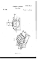
Fig. 7 represents the picker, which consists tr the main cylinder or pickera a a, sup- "ported on the, frame I) b. This cylinder may i be three feet diameter and two to three feet long. The teeth are one inch long and round,
and three-'eighths inch thick at the .root, and
come regularly to-a point. They are one inch apart laterally in each row, and about twelve to fourteen rows on the cylinder; but the teeth in each row are so placed that in the rcvolu-x 'tion they make circles around the, cylinder as if the teeth were half that distance asunder. c'
The effect of the machines repre-i,
place,) to
strippers and brushes. 10 is a pulley on the and c are strippers, six inches diameter, including the teeth, which project one-fourth of an inch, and are about halfan inch apart laterally, andin lateral rows one inch apartaround the cylinder, the teeth of one-eighth wire and pointed. d d are workers, whose cylinders are six inches diameter, including the teeth. The teeth in these are the same size as those in the main cylinder, and'the same distance apart. 0 e is another-worker, twelve to eighteen inches diameter, and the teeth the same size and distance apart asthose last described. The strippers and workers are supported on an iron arch, a; x, from which project the puppet-heads,-as y y, &c., in Figs. 7 and 8. f f
' f is a cylindrical brush of twelve to fourteen inches diameter. There may be four rows of brushes. The brushes may be of bristles or a mixture of bristles and wire- The objector these brushes is to clear the teeth from the oakum on the main cylinder. This brush is similarfito the brush of the eotton-gin. g g is an. additional-brush, with two or more rows of brushes like the one just described. This brush is' to clean the teeth of worker e. h h are rollers to receive an apron, which is Shown by the dotted lines z 2'. On this apron the tow is spread, and it is introduced to the main picke'r'by means of the fluted feed-rollers k k.
Fig. 8 represents Fig; 7 turned around, the lower part of the side easing withdrawn, so as to show part of the end of the main picker and the raking position of the teeth, as a a; b 1),- the concave curb or casing. e is the vent. l 2 4 are the same parts in both Figs. 7 and 8. Z, Fig. 8, is a pulley which drives the machine; of m, a belt which communicates motionfrom Z to pulley n, on the shaft of the main' picker. From pulley 0, Fig. 7, on the other end of the shaft of the main picker, a belt, p p p p 1') passes round the pulleys 5 and 6 of the strippers and the pulleys 7 and 8 'of the brushes," (q being a mere roller, to carry the belt conveniently to its proper give the requisite motion to the 'der feed roller.
shaft of the main picker, which, by the belt 11, gives motion to pulley 12, on a pin-shaft attached to the frame of the machine. Immediately behind pulley 12 on the pin-shaft is a pinion, which works into cog-wheel13, which cog-wheel is on shaft of worker e c. On the Other end of the shaft of worker c is the pulley q, Fig. 8, from which, by means of the belt z z z z z, the workers 3 3 and 1 of the feedroller are moved. 8 is a tightening-pulley. t, Fig. 7, is a pinion on the end of thcupper feed-roller, gearing into a, a pinion on the unu gears into n, a pinion-on a pin-shaft, to give motion to 'w, a pinion on the end of the innerapron-roller. The main cylinder or picker a a, Fig. 7, turns upward from the feeders. and brushes move contrary. to it. The teeth of the strippers and brushes run the same speed as those of the main cylinder, which makes about two hundred and fifty revolutions in a minute; The teeth of the workers niay'run about one-fifth to one tenth as fast as the others. .The main picker, with the feeding'- rollers, which feeding rollers must be flutedor toothed so as to firmly hold the stud to let thepicker operate, will pick oakum when the rope is prepared byv steaming and beating, as before described, but not so well 'as with the additional workers and strippers.
YVe claim as our invention and desire to secure by Letters Patent 3 The combination of the machine for'pielc ing represented by Figs. 7 and 8, with the soaking, steam, and boiling apparatus, Figs. 2 and 4, and breaker, Fig. 3, the heaters, Fig. 5, the pressers, Fig. o, and the. knife, Fig. 1 that is to say, the combination of the pickinginachine with each of the other machines separately and with the whole of themfor the purpose and in the manner described.
J NO. STAN SBURY.
v WILLIAM RIDG UVAY, JR.
\Vitn'esses:
LEVI WILLIAMS, N. STANSBURY.
The workers, strippers,
Publications (1)
| Publication Number | Publication Date |
|---|---|
| US2428A true US2428A (en) | 1842-01-17 |
Family
ID=2062719
Family Applications (1)
| Application Number | Title | Priority Date | Filing Date |
|---|---|---|---|
| US2428D Expired - Lifetime US2428A (en) | Improvement in the combination of machinery for picking oakum |
Country Status (1)
| Country | Link |
|---|---|
| US (1) | US2428A (en) |
-
0
- US US2428D patent/US2428A/en not_active Expired - Lifetime
Similar Documents
| Publication | Publication Date | Title |
|---|---|---|
| US2428A (en) | Improvement in the combination of machinery for picking oakum | |
| US4857A (en) | Machinery fob cutting flocks | |
| DE624646C (en) | Device for debarking tree trunks | |
| US352977A (en) | Machine for removing the fiber from jutej | |
| DE856401C (en) | Bran beating and spinning machine | |
| US511352A (en) | Breaking and scutching machine for flax | |
| US446791A (en) | Fibrous plants | |
| US18564A (en) | Machinery for burring wool on the pelt | |
| US59503A (en) | Improvement in machines for breaking and cleaning flax | |
| US2725598A (en) | Bast and bark fibre decorticating machine | |
| US190476A (en) | Improvement in machines for treating flax, hemp, and other similar plants | |
| DE546161C (en) | Machine with a comb drum for exposing the fibers from ramie and other non-corrugated fiber plants | |
| US131546A (en) | Edwaed jones | |
| US145613A (en) | Improvement in fiber-disintegrators | |
| US3490102A (en) | Method for preparing chignons | |
| US434112A (en) | Kreis | |
| US2723A (en) | Improvement in machines for picking oakum | |
| US261A (en) | Machine for hackling hemp and other lint | |
| US4114A (en) | Improvement in hemp-machines | |
| USRE4671E (en) | Improvement in machines for preparing sisal grass and like substances | |
| US2175A (en) | Machine for cleansing wool and cotton from burs | |
| US8218A (en) | Improvement in machines for dressing sisal hemp | |
| AT160831B (en) | Method and device for producing loose, fine-fiber masses. | |
| US241557A (en) | charles meyer | |
| US126337A (en) | Improvement in machines for treating fibrous plants |