US2427770A - Snap clip - Google Patents
Snap clip Download PDFInfo
- Publication number
- US2427770A US2427770A US527438A US52743844A US2427770A US 2427770 A US2427770 A US 2427770A US 527438 A US527438 A US 527438A US 52743844 A US52743844 A US 52743844A US 2427770 A US2427770 A US 2427770A
- Authority
- US
- United States
- Prior art keywords
- clip
- hook
- support
- apertures
- fastening
- Prior art date
- Legal status (The legal status is an assumption and is not a legal conclusion. Google has not performed a legal analysis and makes no representation as to the accuracy of the status listed.)
- Expired - Lifetime
Links
- 238000009434 installation Methods 0.000 description 10
- 210000002105 tongue Anatomy 0.000 description 3
- 230000000694 effects Effects 0.000 description 2
- 239000002184 metal Substances 0.000 description 2
- 229910000639 Spring steel Inorganic materials 0.000 description 1
- 229910000831 Steel Inorganic materials 0.000 description 1
- AGOYDEPGAOXOCK-KCBOHYOISA-N clarithromycin Chemical compound O([C@@H]1[C@@H](C)C(=O)O[C@@H]([C@@]([C@H](O)[C@@H](C)C(=O)[C@H](C)C[C@](C)([C@H](O[C@H]2[C@@H]([C@H](C[C@@H](C)O2)N(C)C)O)[C@H]1C)OC)(C)O)CC)[C@H]1C[C@@](C)(OC)[C@@H](O)[C@H](C)O1 AGOYDEPGAOXOCK-KCBOHYOISA-N 0.000 description 1
- 238000010276 construction Methods 0.000 description 1
- 229920001971 elastomer Polymers 0.000 description 1
- 230000037431 insertion Effects 0.000 description 1
- 238000003780 insertion Methods 0.000 description 1
- 238000009413 insulation Methods 0.000 description 1
- 239000000463 material Substances 0.000 description 1
- 230000000750 progressive effect Effects 0.000 description 1
- 239000005060 rubber Substances 0.000 description 1
- 239000010959 steel Substances 0.000 description 1
- 229920003051 synthetic elastomer Polymers 0.000 description 1
- 239000005061 synthetic rubber Substances 0.000 description 1
Images
Classifications
-
- F—MECHANICAL ENGINEERING; LIGHTING; HEATING; WEAPONS; BLASTING
- F16—ENGINEERING ELEMENTS AND UNITS; GENERAL MEASURES FOR PRODUCING AND MAINTAINING EFFECTIVE FUNCTIONING OF MACHINES OR INSTALLATIONS; THERMAL INSULATION IN GENERAL
- F16L—PIPES; JOINTS OR FITTINGS FOR PIPES; SUPPORTS FOR PIPES, CABLES OR PROTECTIVE TUBING; MEANS FOR THERMAL INSULATION IN GENERAL
- F16L3/00—Supports for pipes, cables or protective tubing, e.g. hangers, holders, clamps, cleats, clips, brackets
- F16L3/08—Supports for pipes, cables or protective tubing, e.g. hangers, holders, clamps, cleats, clips, brackets substantially surrounding the pipe, cable or protective tubing
- F16L3/12—Supports for pipes, cables or protective tubing, e.g. hangers, holders, clamps, cleats, clips, brackets substantially surrounding the pipe, cable or protective tubing comprising a member substantially surrounding the pipe, cable or protective tubing
- F16L3/123—Supports for pipes, cables or protective tubing, e.g. hangers, holders, clamps, cleats, clips, brackets substantially surrounding the pipe, cable or protective tubing comprising a member substantially surrounding the pipe, cable or protective tubing and extending along the attachment surface
- F16L3/1233—Supports for pipes, cables or protective tubing, e.g. hangers, holders, clamps, cleats, clips, brackets substantially surrounding the pipe, cable or protective tubing comprising a member substantially surrounding the pipe, cable or protective tubing and extending along the attachment surface the member being of metal, with or without an other layer of other material
Definitions
- This invention relates to clips for supporting -conduits or wires in aircraft 4and the present application is a division of my pending application for United States Letters Patent, Serial No. 420,577, now Patent No. 2,379,893, filed November 26, 1941, for Conduit clip and securing means.
- An object of this invention is to provide a snap clip of the character described which may be quickly and easily snapped around a conduit or wire so that it will remain in the desired position thereon to facilitate installation of the clip on support therefor.
- Another object of my invention is to provide a clip Vsuch as described in which a hook means embodied in apertured ends of the clip makes it ypossible to effect a quick temporary clamping or fastening of the clip around the object to be .sup-5 ported thereby with said ends held in opposed relation and the apertures therein disposed in registration with one another for reception of a fastening by means of which the clip is tightly clamped on the object and secured to a support therefor.
- a further object of my invention is to provide a clip of the character described in which the apertured ends of the object-embracing strap when brought together in closing the strap around the object will be hooked together with a snap action so that the apertures in said ends will be aligned for reception of a fastening.
- lAnother object is to provide Ia clip of the character described wherein the hook which holds the apertured ends together preliminary to applying the fastening, may be used to hook the clip to the support so that the apertures in said ends will be aligned with a fastening-receiving opening in the support to facilitate the application of said fastening to complete the installation of the clip.
- Yet another object is to provide a clip of the character described in which a spring nut is carried on one of the apertured ends of the clip so that when the hook member on one of said ends is applied to the .support for the Aclip to temporarily hold it thereon, the opening in the spring nut and the apertures in said ends are aligned with the fastening-receiving opening in the support ⁇ thereby making for a quick and easy application of the fastening to complete -the installation of the clip.
- a further object is to provide a clip in which the hook means and nut are integral parts of a single piece of resilient strap metal and are readily and easily formed thereon, thereby eliminating separate and extraneous parts, the fastening such .2 as a screw or bolt being the only extra or separate part necessary for a complete installation.
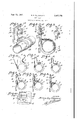
- Fig. l is a perspective view of a clip installation embodying my invention.
- Fig. 2 is a fragmentary part side elevation and part sectional Vvievv ofthe clip as shown in Fig. 1;
- Fig. 3 is a. fragmentary sectional view taken on the line 3-3 of Fig. 2;
- Fig. 4 is -a fragmentary side elevation and part sectional View of the clip showing in full lines the normal position thereof before application to an object to be supported and indicating zby the dashed lines how the ends of the clip are brought together when the clip is rst applied to the A object;
- Fig. 5 is a view similar to Fig. 4 showing the ends of the clip when brought into contact with one another and indicating how the hook elements ride one past the other;
- Fig. 6 is a view similar to Figs. 4 and 5 .showing the ends of the clip hooked together with the apertures therein aligned andthe cli-p temporarily held or clamped on the object;
- Fig; 7 is a view similar to Fig. 6 showing how the clip is applied to the support in order to be hooked thereto;
- Fig. 8 is a View similar to Fig. v6 showing how the hook is passed through an opening preliminary to being hooked to an Vedge thereof;
- Fig. ⁇ 9 similar to Fig. 8 is a View showing the clip hooked to the support with the apertures 'in the ends of the clip, the nut and the fasteningreceiving apertures in the support in registrati-on for reception of the fastening; 1
- Fig. 10 is a fragmentary elevational View of the installation shown in Fig. 9.
- l designates a clip embodying my invention
- ⁇ 2 represents a conduit line which may of course be a group of Wires or other object subject to support
- 3 designates a support on which the cliiO is installed.
- the clip includes a strap 4 of spring steel or other resilient metal shaped normally as shown in full lines in Fig. 4 so that it is in the form of an open loop subject to being readily positioned to embrace the conduit 2 or wires or other object to be supported thereby, and having apertured and outwardly extended ends 5 and 6 adapted to be brought together to clamp the clip on the object and dispose said ends so that a fastening such as the screw 'I may be inserted through an opening 8 in the support 3 and through the apertures in said ends, to install the clip as shown in Figs. 1, 2 and 3.
- a cushion 9 of insulation and yieldable material such as rubber or synthetic rubber is mounted on the loop portion f the strap 4 to cushion and prevent chafing and undue wear of the object supported in the clip.
- This cushion has angular marginal ilaps or anges I0 arranged to engage the longitudinal side edge and outer face of the strap to hold the cushion in place.
- the apertured ends and 6 are disposed so that when forced from position shown in full lines in Fig. 4 to contacting position shown in Fig. 5, while the strap embraces the conduit or other object, the strap will encircle the conduit and said ends will be near a position of parallelism with the apertures therein nearly in registration with one another.
- the end 5 of the strap is bent over and inwardly toward the body of the clip to form a hook II adapted to hook over the end or lip portion afforded by the upper edge II of the end 6 of the strap.
- the hook II is brought into contact With the end 6 as shown in Fig. 5 and the operator forces said ends together the hook II will ride upwardly or cam over the lip edge II while the latter rides under the hook, with a sharp action and said ends willV be hooked together as shown in Fig, 6 with the apertures therein aligned for reception of the screw 1.
- the hook means holds the clip in desired position on the object in a sub-assembly, with the clip ready for installation on the support thereby greatly facilitating a quick and easy installation of the clip and object supported thereby.
- the installation of the clip hereof is further facilitated by making the hook of such size and form that in addition to holding the clip temporarily in position on the conduit wires or object, it may be applied through an opening I2 in the support 3 or to an edge of the support to hook and hold the clip in position to completely install it.
- Figs. 7 and 8 show the progressive operations which may be easily eiected to hook the clip on the support as shown in Figs. 9 and 10, it only being necessary to force it against the support as shown in Figs. '7 and 8 so that the hook will pass through the opening I2 and snap over the edge of the opening as shown in Figs. 9 and 10.
- the opening I2 is registered with apertures in the ends 5 and 6 for a ready insertion of the screw 1.
- the end 5 of the strap has two spring tongues I3 struck out from opposite sides of the aperture therein to form a spring nut wherein the ends of said tongues engage opposite sides of the screw I under tension and the screw cuts into said ends wherefor the tongues are tensioned and serve as a nut to hold the screw in place.
- a resilient strap formed with an open loop portion adapted to embrace the object to be supported and having normally spaced apart apertured ends extending outwardly irom said loopv portion and adapted to be brought together to clamp the clip on the object, and a hook on one of said ends adapted to hook over an edge of the other of said ends with a snap action when said ends are brought together, to clamp the clip on the object and hold said ends with the apertures therein in registration for reception of a fastening, said hook having an extent such that without unhooking said ends, it may be hooked over an edge of a support to hold the clip thereon with the apertures in said ends still in registration for reception of the fastening.
- a resilient strap formed with an open loop portion adapted to embrace the object to be supported and having normally spaced apart apertured ends extending outwardly from said loop portion and adapted to be brought together to clamp the clip on the object, and a hook on one of said ends adapted to hook over an edge of the other of said ends with a snap action when said ends are brought together, to clamp the clip on the obj ect and hold said ends with the apertures therein in registration for reception of a fastening, said hook having an extent such that, without unhooking said ends, it may be hookedover an edge of a support to effect alignment of a fastening receiving opening in said support with the aligned apertures in the ends of said clip.
Landscapes
- Engineering & Computer Science (AREA)
- General Engineering & Computer Science (AREA)
- Mechanical Engineering (AREA)
- Clamps And Clips (AREA)
Description
Sept. 23, 1947. H. R. ELLINWQOD SNAP CLIP Original Filed Nov. 26, 1941 INI/EN TOR.
Patented Sept. 23, 1947 SNAP CLIP Herman Ray Ellinwood, Burbank, Calif., assignor to Adel Precision Products Corp., a corporation of California Original application November 26, 1941, `Serial Divided and this application March 21, 1944, Serial No. 527,438
3 Claims.
This invention relates to clips for supporting -conduits or wires in aircraft 4and the present application is a division of my pending application for United States Letters Patent, Serial No. 420,577, now Patent No. 2,379,893, filed November 26, 1941, for Conduit clip and securing means.
An object of this invention is to provide a snap clip of the character described which may be quickly and easily snapped around a conduit or wire so that it will remain in the desired position thereon to facilitate installation of the clip on support therefor.
Another object of my invention is to provide a clip Vsuch as described in which a hook means embodied in apertured ends of the clip makes it ypossible to effect a quick temporary clamping or fastening of the clip around the object to be .sup-5 ported thereby with said ends held in opposed relation and the apertures therein disposed in registration with one another for reception of a fastening by means of which the clip is tightly clamped on the object and secured to a support therefor.
A further object of my invention is to provide a clip of the character described in which the apertured ends of the object-embracing strap when brought together in closing the strap around the object will be hooked together with a snap action so that the apertures in said ends will be aligned for reception of a fastening.
lAnother object is to provide Ia clip of the character described wherein the hook which holds the apertured ends together preliminary to applying the fastening, may be used to hook the clip to the support so that the apertures in said ends will be aligned with a fastening-receiving opening in the support to facilitate the application of said fastening to complete the installation of the clip.
Yet another object is to provide a clip of the character described in which a spring nut is carried on one of the apertured ends of the clip so that when the hook member on one of said ends is applied to the .support for the Aclip to temporarily hold it thereon, the opening in the spring nut and the apertures in said ends are aligned with the fastening-receiving opening in the support `thereby making for a quick and easy application of the fastening to complete -the installation of the clip.
A further object is to provide a clip in which the hook means and nut are integral parts of a single piece of resilient strap metal and are readily and easily formed thereon, thereby eliminating separate and extraneous parts, the fastening such .2 as a screw or bolt being the only extra or separate part necessary for a complete installation. With the foregoing objects in view, together with such -other objects and advantages as may subsequently appear, the .invention resides in the parts and in the combination, construction and arrangement of parts hereinafter described and claimed, and illustrated by way of example in the accompanying drawing in which:
Fig. l is a perspective view of a clip installation embodying my invention; A
Fig. 2 is a fragmentary part side elevation and part sectional Vvievv ofthe clip as shown in Fig. 1; Fig. 3 is a. fragmentary sectional view taken on the line 3-3 of Fig. 2;
Fig. 4 is -a fragmentary side elevation and part sectional View of the clip showing in full lines the normal position thereof before application to an object to be supported and indicating zby the dashed lines how the ends of the clip are brought together when the clip is rst applied to the A object;
Fig. 5 is a view similar to Fig. 4 showing the ends of the clip when brought into contact with one another and indicating how the hook elements ride one past the other;
Fig. 6 is a view similar to Figs. 4 and 5 .showing the ends of the clip hooked together with the apertures therein aligned andthe cli-p temporarily held or clamped on the object;
Fig; 7 is a view similar to Fig. 6 showing how the clip is applied to the support in order to be hooked thereto;
Fig. 8 is a View similar to Fig. v6 showing how the hook is passed through an opening preliminary to being hooked to an Vedge thereof;
Fig. `9 similar to Fig. 8 is a View showing the clip hooked to the support with the apertures 'in the ends of the clip, the nut and the fasteningreceiving apertures in the support in registrati-on for reception of the fastening; 1
Fig. 10 is a fragmentary elevational View of the installation shown in Fig. 9.
Referring to the drawing more specifically, l designates a clip embodying my invention, `2 represents a conduit line which may of course be a group of Wires or other object subject to support, and 3 designates a support on which the cliiO is installed.
As here provided the clip includes a strap 4 of spring steel or other resilient metal shaped normally as shown in full lines in Fig. 4 so that it is in the form of an open loop subject to being readily positioned to embrace the conduit 2 or wires or other object to be supported thereby, and having apertured and outwardly extended ends 5 and 6 adapted to be brought together to clamp the clip on the object and dispose said ends so that a fastening such as the screw 'I may be inserted through an opening 8 in the support 3 and through the apertures in said ends, to install the clip as shown in Figs. 1, 2 and 3.
A cushion 9 of insulation and yieldable material such as rubber or synthetic rubber is mounted on the loop portion f the strap 4 to cushion and prevent chafing and undue wear of the object supported in the clip. This cushion has angular marginal ilaps or anges I0 arranged to engage the longitudinal side edge and outer face of the strap to hold the cushion in place.
As here provided the apertured ends and 6 are disposed so that when forced from position shown in full lines in Fig. 4 to contacting position shown in Fig. 5, while the strap embraces the conduit or other object, the strap will encircle the conduit and said ends will be near a position of parallelism with the apertures therein nearly in registration with one another.
In accordance with this invention the end 5 of the strap is bent over and inwardly toward the body of the clip to form a hook II adapted to hook over the end or lip portion afforded by the upper edge II of the end 6 of the strap. Thus when the hook II is brought into contact With the end 6 as shown in Fig. 5 and the operator forces said ends together the hook II will ride upwardly or cam over the lip edge II while the latter rides under the hook, with a sharp action and said ends willV be hooked together as shown in Fig, 6 with the apertures therein aligned for reception of the screw 1.
The hook means holds the clip in desired position on the object in a sub-assembly, with the clip ready for installation on the support thereby greatly facilitating a quick and easy installation of the clip and object supported thereby.
The installation of the clip hereof is further facilitated by making the hook of such size and form that in addition to holding the clip temporarily in position on the conduit wires or object, it may be applied through an opening I2 in the support 3 or to an edge of the support to hook and hold the clip in position to completely install it.
Figs. 7 and 8 show the progressive operations which may be easily eiected to hook the clip on the support as shown in Figs. 9 and 10, it only being necessary to force it against the support as shown in Figs. '7 and 8 so that the hook will pass through the opening I2 and snap over the edge of the opening as shown in Figs. 9 and 10. The opening I2 is registered with apertures in the ends 5 and 6 for a ready insertion of the screw 1.
To render the final installation easier and save time, the end 5 of the strap has two spring tongues I3 struck out from opposite sides of the aperture therein to form a spring nut wherein the ends of said tongues engage opposite sides of the screw I under tension and the screw cuts into said ends wherefor the tongues are tensioned and serve as a nut to hold the screw in place. When ing normally spaced apart apertured ends extending outwardly from said loop portion and adapted y to be brought together to clamp the clip on the object, and a hook on one of said ends adapted to hook over an edge of the other of said ends when said ends are brought together, to clamp the clip on the object and hold said ends with the apertures therein in registration for reception of a fastening, said hook serving additionally as a means for aligning said registered apertures with a fastening receiving aperture in a supporting structure.
2. In a clip for supporting an object, a resilient strap formed with an open loop portion adapted to embrace the object to be supported and having normally spaced apart apertured ends extending outwardly irom said loopv portion and adapted to be brought together to clamp the clip on the object, and a hook on one of said ends adapted to hook over an edge of the other of said ends with a snap action when said ends are brought together, to clamp the clip on the object and hold said ends with the apertures therein in registration for reception of a fastening, said hook having an extent such that without unhooking said ends, it may be hooked over an edge of a support to hold the clip thereon with the apertures in said ends still in registration for reception of the fastening.
3. In a clip for supporting an object, a resilient strap formed with an open loop portion adapted to embrace the object to be supported and having normally spaced apart apertured ends extending outwardly from said loop portion and adapted to be brought together to clamp the clip on the object, and a hook on one of said ends adapted to hook over an edge of the other of said ends with a snap action when said ends are brought together, to clamp the clip on the obj ect and hold said ends with the apertures therein in registration for reception of a fastening, said hook having an extent such that, without unhooking said ends, it may be hookedover an edge of a support to effect alignment of a fastening receiving opening in said support with the aligned apertures in the ends of said clip.
HERMAN RAY ELLINWOOD.
REFERENCES CITED The following references are of record in the file of this patent:
Publication of Tinnerman Productsv Inc., in Steel, on April 2'7, 1942; pages 98 to 100 on Harness Clamp 3044.
Number
Priority Applications (1)
| Application Number | Priority Date | Filing Date | Title |
|---|---|---|---|
| US527438A US2427770A (en) | 1941-11-26 | 1944-03-21 | Snap clip |
Applications Claiming Priority (2)
| Application Number | Priority Date | Filing Date | Title |
|---|---|---|---|
| US420577A US2379893A (en) | 1941-11-26 | 1941-11-26 | Conduit clip and securing means |
| US527438A US2427770A (en) | 1941-11-26 | 1944-03-21 | Snap clip |
Publications (1)
| Publication Number | Publication Date |
|---|---|
| US2427770A true US2427770A (en) | 1947-09-23 |
Family
ID=27024919
Family Applications (1)
| Application Number | Title | Priority Date | Filing Date |
|---|---|---|---|
| US527438A Expired - Lifetime US2427770A (en) | 1941-11-26 | 1944-03-21 | Snap clip |
Country Status (1)
| Country | Link |
|---|---|
| US (1) | US2427770A (en) |
Cited By (10)
| Publication number | Priority date | Publication date | Assignee | Title |
|---|---|---|---|---|
| US2784772A (en) * | 1957-03-12 | Clip for supporting the end of a spring strip | ||
| US3022044A (en) * | 1958-11-28 | 1962-02-20 | Gugino Samuel | Combined brace band and tension bar retainer for fencing |
| US3035802A (en) * | 1958-03-13 | 1962-05-22 | Westinghouse Electric Corp | Pole top adapter for streetlighting transformer |
| US3254866A (en) * | 1964-07-21 | 1966-06-07 | Jet Line Products Inc | Method and means for supporting conduits |
| US4681388A (en) * | 1985-04-04 | 1987-07-21 | Hirose Elec. Co., Ltd. | Cord clamping mechanism |
| US6394399B2 (en) * | 2000-03-06 | 2002-05-28 | Eads Deutschland Gmbh | Cable holder for attaching cables to a support structure |
| US20060054758A1 (en) * | 2004-09-16 | 2006-03-16 | Simpson Allen H | Fixture for holding a preform during a heating process |
| US20070257161A1 (en) * | 2006-05-03 | 2007-11-08 | Rasmussen Gmbh | Clamp for securing a tubular or hose-shaped object |
| US20170227142A1 (en) * | 2016-02-18 | 2017-08-10 | Junjie Huang | Pipe hanger |
| US11274771B2 (en) * | 2017-02-15 | 2022-03-15 | Norma Germany Gmbh | Clamp with clamp band and rubber profile |
Citations (1)
| Publication number | Priority date | Publication date | Assignee | Title |
|---|---|---|---|---|
| US2339093A (en) * | 1942-10-15 | 1944-01-11 | Clyde E Metheny | Snap clamp |
-
1944
- 1944-03-21 US US527438A patent/US2427770A/en not_active Expired - Lifetime
Patent Citations (1)
| Publication number | Priority date | Publication date | Assignee | Title |
|---|---|---|---|---|
| US2339093A (en) * | 1942-10-15 | 1944-01-11 | Clyde E Metheny | Snap clamp |
Cited By (15)
| Publication number | Priority date | Publication date | Assignee | Title |
|---|---|---|---|---|
| US2784772A (en) * | 1957-03-12 | Clip for supporting the end of a spring strip | ||
| US3035802A (en) * | 1958-03-13 | 1962-05-22 | Westinghouse Electric Corp | Pole top adapter for streetlighting transformer |
| US3022044A (en) * | 1958-11-28 | 1962-02-20 | Gugino Samuel | Combined brace band and tension bar retainer for fencing |
| US3254866A (en) * | 1964-07-21 | 1966-06-07 | Jet Line Products Inc | Method and means for supporting conduits |
| US4681388A (en) * | 1985-04-04 | 1987-07-21 | Hirose Elec. Co., Ltd. | Cord clamping mechanism |
| US6394399B2 (en) * | 2000-03-06 | 2002-05-28 | Eads Deutschland Gmbh | Cable holder for attaching cables to a support structure |
| US20060054758A1 (en) * | 2004-09-16 | 2006-03-16 | Simpson Allen H | Fixture for holding a preform during a heating process |
| US20080251959A1 (en) * | 2004-09-16 | 2008-10-16 | Simpson Allen H | Method of manufacturing a carbon-carbon brake disc |
| US8105511B2 (en) | 2004-09-16 | 2012-01-31 | Honeywell International Inc. | Method of manufacturing a carbon-carbon brake disc |
| US20070257161A1 (en) * | 2006-05-03 | 2007-11-08 | Rasmussen Gmbh | Clamp for securing a tubular or hose-shaped object |
| US20110204192A1 (en) * | 2006-05-03 | 2011-08-25 | Norma Germany Gmbh | Clamp for securing a tubular or hose-shaped object |
| US8020814B2 (en) * | 2006-05-03 | 2011-09-20 | Norma Germany Gmbh | Clamp for securing a tubular or hose-shaped object |
| US9133963B2 (en) | 2006-05-03 | 2015-09-15 | Norma Germany Gmbh | Clamp for securing a tubular or hose-shaped object |
| US20170227142A1 (en) * | 2016-02-18 | 2017-08-10 | Junjie Huang | Pipe hanger |
| US11274771B2 (en) * | 2017-02-15 | 2022-03-15 | Norma Germany Gmbh | Clamp with clamp band and rubber profile |
Similar Documents
| Publication | Publication Date | Title |
|---|---|---|
| US2413772A (en) | Clip for multiple conduit supports | |
| US1963908A (en) | Clamp | |
| US2338006A (en) | Supporting clip for conduits | |
| US2166916A (en) | Clip for mounting cables and like objects | |
| US2453980A (en) | Fastening device for cables, wires, or the like | |
| US2366041A (en) | Wire supporting clip | |
| US2432492A (en) | Combined nut fastener and grounding member | |
| US3131447A (en) | Mounting clamps | |
| US2427770A (en) | Snap clip | |
| US2875805A (en) | Mounting retainer having raised flanges to engage head of stud | |
| US2632217A (en) | Separable clamping device | |
| US3376004A (en) | Snap clamp | |
| US2390750A (en) | Fastening device | |
| US4379536A (en) | Means for retaining a rod-shaped material | |
| US2215283A (en) | Line supporting clip | |
| US2938692A (en) | Cable clamp support | |
| US2338659A (en) | Conduit clip and supporting bracket | |
| US2408572A (en) | Wire or conduit clip | |
| US2431379A (en) | Snap clamp | |
| US2068932A (en) | Fastening device | |
| US2496866A (en) | Fastening device | |
| US2338658A (en) | Temporary holding device for conduit clips | |
| US2445481A (en) | Cable hanger | |
| US2340560A (en) | Flexible pipe clamp | |
| US2222810A (en) | Clamp for connecting an insulator to a post |