US2425709A - Blowpipe nozzle - Google Patents
Blowpipe nozzle Download PDFInfo
- Publication number
- US2425709A US2425709A US478202A US47820243A US2425709A US 2425709 A US2425709 A US 2425709A US 478202 A US478202 A US 478202A US 47820243 A US47820243 A US 47820243A US 2425709 A US2425709 A US 2425709A
- Authority
- US
- United States
- Prior art keywords
- oxygen
- passage
- nozzle
- acetylene
- stream
- Prior art date
- Legal status (The legal status is an assumption and is not a legal conclusion. Google has not performed a legal analysis and makes no representation as to the accuracy of the status listed.)
- Expired - Lifetime
Links
Images

Classifications
-
- F—MECHANICAL ENGINEERING; LIGHTING; HEATING; WEAPONS; BLASTING
- F23—COMBUSTION APPARATUS; COMBUSTION PROCESSES
- F23D—BURNERS
- F23D14/00—Burners for combustion of a gas, e.g. of a gas stored under pressure as a liquid
- F23D14/46—Details, e.g. noise reduction means
- F23D14/48—Nozzles
- F23D14/52—Nozzles for torches; for blow-pipes
- F23D14/54—Nozzles for torches; for blow-pipes for cutting or welding metal
-
- Y—GENERAL TAGGING OF NEW TECHNOLOGICAL DEVELOPMENTS; GENERAL TAGGING OF CROSS-SECTIONAL TECHNOLOGIES SPANNING OVER SEVERAL SECTIONS OF THE IPC; TECHNICAL SUBJECTS COVERED BY FORMER USPC CROSS-REFERENCE ART COLLECTIONS [XRACs] AND DIGESTS
- Y10—TECHNICAL SUBJECTS COVERED BY FORMER USPC
- Y10S—TECHNICAL SUBJECTS COVERED BY FORMER USPC CROSS-REFERENCE ART COLLECTIONS [XRACs] AND DIGESTS
- Y10S266/00—Metallurgical apparatus
- Y10S266/904—Blowpipe cutting heads
Definitions
- This invention relates to blowpipe nozzles and more particularly to-nozzles for simultaneously discharging an oxygen stream and a. post-mixed Oxy-acetylene preheating llame useful in thermochemically cutting, desurfacing, deseaming,
- the main objects of the invention are to provide an improved preheating and oxidizing gas discharge nozzle of the post-mixed or externally mixed type, that is to say, of the type adapted to mix the dame-forming gases' such as oxygen and acetylene outside of the nozzle; an improved postmixed nozzle for desurfacing or deseamlng ferrous metal bodies; and an improved blowpipe adapted for heating and oxidizing work such as thermochemically cutting or conditioning ferrous'metal with oxygen.
- Fig. v3 is a detail view partially in side elevation and partially in section of the end cap
- Fig, 4 is a cross-sectional view of the cap taken on line 4-4 of Fig, 3;
- a desurfacing nozzle for example, in which fuel gas such as acetylene is fed to a region in front of the cutting oxygen orifice and mixes with a re1- atively small quantity of oxygen immediately after the latter is discharged by the cutting oxygen passage, to produce a post-mixed oxy-acetylene flame for initially heating the work.
- the flow of cutting oxygen is then increased to a desurfacing velocity without changing the ow of acetylene.
- the nozzle may be of the round or fiat slotted oxygen varnish type and may be used for cutting as well as desurfacing and deseamng.
- the oxidizing gas stream may contain powdered material such as iron for starting purposes with ferrous metal solids, or for continuously promoting the desired thermochemical reaction in working oxidation resistant solids such as stainless steel.
- Fig. 1 is a longitudinal cross-sectional view of a post-mixed desurfacing nozzle exemplifying the invention
- Fig. 2 is an enlarged view in front elevation of the discharge end of the nozzle, part of the end Fig. 5 is a. view similar to Fig. 2 of a, modification for deseaming;
- Fig. 6 is a reduced fragmentary sectional view taken on line 6-6 of Fig. 5; Y
- Fig. 7 is an enlarged view in front elevation of a modification in which a plurality of grooves are provided on the end face of the nozzle body for the acetylene slots, a, portion of the end cap of the nozzle being broken away to show the end face of the body member;
- Fig. 8 is a view in longitudinal cross section of the modification shown in Fig. 7;
- Fig. 9 is a view in front elevation of the discharge end of a one-piece post-mixed nozzle embodying features of the invention.
- Fig. 10 is a longitudinal cross-sectional view of the one-piece nozzle shown in Fig. 9.
- a desurfacing nozzle II which comprises an elongated generally tubular body or member II having a central cutting oxygen passage .l2 extending longitudinally therethrough.
- the central oxygen passage I2 is preferably of the shape vshown and claimed in Patent No. 2,267,623, and includes an inlet portion I3 of constant diameter, a ared portion I 4, a short portion I6 of constant diameter and a single outlet portion I 'I which gradually changes from circular to oblate or flat cross section, the discharge end of the central oxygen passage I2 being oblong as shown at I8.
- the oxygen is discharged from the single outlet I8 in the form ofA a single solid or compact stream as distinguished from a tubular stream or a plurality of parallel streams.
- the tubular body II is also provided with a plurality of acetylene passages I9 arranged in spaced substantially parallel relation to the oxygen passage I 2, all of the passages I2 and I9 terminating in an end face 20 of the member II which lies in a plane disposed at right angles to the longitudinal axis of the member II.
- the gas inlet end of the tubular body II is provided with a pair of radially and longitudinally spaced frusto-conical annular seats 2
- the nozzle IIJ is coupled to the blowpipe head in the usual way so that acetylene is delivered to the acetylene passages I9 and oxygen is delivered to the central oxygen passage l2.
- the tubular body Il is provided with a cylindrical end portion 25 of reduced diameter between the end face 20 and an annular shoulder 26.
- an end cap 21 having a. cylindrical skirt 28 fitting such end portion, the edge of the skirt being bronze welded or silver soldered at 29 .to the shoulder 26 to secure the cap 28 and body member II in assembled relation.
- the cap 21 includes a bottom panel 30 having a shoulder 3I seated on the end face 28 to space the inner surface 32 of the panel 30 at a fixed distance from the face 20.
- are shaped so as to provide with the nozzle end face 20 a. senil-circular chamber or slot 32' around the discharge ends 33 of each group of acetylene passages I9, there being three such acetylene passages above and three below the oxygen orifice I8 in the present example.
- the bottom panel 30 of the cap 21 has a transverse opening 34, the inner parallel edges 35 of which are laterally offset with respect to or spaced farther apart than the inner parallel edges 3-6 of the discharge end I8 of the central oxygen passage I2.
- the orifice I8 of the oxygen passage is also provided with a peripheral recess or groove 31.
- the recess 31 causes eddy currents on the surface layer of the single discharging oxygen stream and thus provides a fringe of low velocity oxygen around the otherwise unbroken or solid stream of oxygen, for admixture with the acetylene, to form a post-mixed preheating flame, when the oxygen stream is discharged at a desurfacing velocity; and prevents such flame being blown out,
- acetylene flowing through the acetylene passages I9 into chambers 32 is discharged as two thin wide streams from chambers 32' and directed inwardly against the wide upper and lower sides of the single oblong stream of oxygen discharged by the central passage I2 immediately after the oxygen stream leaves the discharge orifice of the passage I2.
- only one acetylene passage I9 might be provided instead of three at each side of the oxygen passage, and also acetylene might be fed against only one side of the discharging oxygen stream, preferably the upper side.
- oxygen is first supplied to the central oxygen passage I2 only in sufficient volume and pressure to mix with the acetylene discharged by the parallel outlets 38 of chambers 32 above and below the slotted oxygen orifice I8 :to produce an externally mixed Oxy-acetylene flamel for heating the work to start the desurfacing operation when the velocity of the oxygen stream is subsequently increased.
- the velocity of the-central oxygen stream discharged by the orifice I8 is then increased to a desired value (depending upon the nature of the operation to be performed, in this case to a ⁇ desurfacing velocity) without altering the quantity of acetylene supplied to the nozzle and discharged against both sides'of the oxygen stream.
- the desurfacing oxygen stream is thereby provided at each of its flat surfaces with a preheating flame composed of a mixture of oxygen and acetylene which is mixed externally of the nozzle, owing to the unique construction of the working end of the nozzle.
- Iron powder or the like may of course be supplied to the oxygen or acetylene before it enters the nozzle, or as it flows through the nozzle, or after it is discharged from the nozzle, for the purpose of starting the reaction with iron bodies or for continuously carrying on the reaction with oxidation resistant bodies.
- a deseaming nozzle 4I of somewhat similar construction to that described above in connection with Figs. 1 to 4, with the exception that the discharge end 4I of the central oxygen passage 42 is round, the opening 43 in the end cap 44 also being round and coaxial with but radially offset with respect to the inner edge of the discharge end of the oxygen passage 42.
- the acetylene passages 45 are arranged in a circle y about and concentric with the central oxygen passage 42, and an integral annular shoulder 46 is provided on the end face 41 of the tubular nozzle body 48, to space the inner surface 49 of the bottom panel 30' of the cap 44 away from the end face 41 of the tubular body 48 of the nozzle 4I).
- the post-mixed nozzles shown in Figs. 1 to 6 of the drawings are subject to a disadvantage in that the narrow acetylene outlets from which the acetylene is discharged inwardly against the sides of the solid stream of oxygen are apt to be changed in width or closed either by expansion ofthe metal or by mechanical abuse of the end panels of the caps.
- Such disadvantage is overcome by the modifications shown in Figs. '1 and 8 in which the bottom panel of the cap engages and is supported by the end face of the tubular body, especially in the areas along the edge of the opening in the bottom panel.
- a blowpipe nozzle comprising a tubular body 6I having a central oxygen passage 62 extending longitudinally therethrough, and also having a plurality of acetylene passages 63 arranged in spaced relation to the oxygen passage 62.
- the discharge ends of the passages 62 and 63 termiend cap 65 having a cylindrical skirt fits the annular end portion of the tubular body, and is secured in place on such memberwith the bottom panel 65 of the cap in supporting relation with the end face 6l of the member 6
- the bottom panel 65 is provided with an opening 66 the inner edges of which are laterally offset with respect to the discharge end 6l of the oxygen passage 62.
- the discharge end 61 of theroxygen passage has a peripheral recess 68 and is entirely open for discharging only a single solid stream of oxygen.
- the end face 64 of the body member 6i is providedwith a plurality of parallel grooves 89 disposed so as to direct the acetylene discharged by the acetylene passages '63 inwardly toward the single stream of oxygen as the latter leaves the discharge end of the oxygen pas-sage B2.
- the grooves 69 are of rectangular cross section so as to provide acetylene slots which discharge the acetylene inwardly against the oxygen stream as it leaves the oxygen passage, there being a groove or slot 6B for each acetylene pas- Since the bottom panel of the cap engages the end face 64 of the body between' the grooves 69, however, the arrangement is such that it is impossible for the panel to close the grooves 69 du to warpage or other injury.
- the modification of the invention shown in Figs. 9 and 10 consists of a one-piece nozzlelli) having a central oxygen passage 8
- the tubular nozzle 80 ' is provided withan oblong opening 84 the inner longitudinal edges of which are laterally offset with respect to the corresponding edgesV of the oblong discharge end 85 of the oxygen passage 8I in the plane 83.
- the nozzle has a periph ⁇ y ber or slot 81 atl each side of the recess 86, each chamber being disposed so as to direct the acetfires or flashbacks which are inherent in blowpipe apparatus which utilizes premixed oxygen and acetylene to produce the preheating flames.
- a blowpipe nozzle comprising an elongated member having a central oxygen passage extending longitudinally therethrough and also having a plurality o f acetylene passages arranged in spaced substantially parallel relation to said oxygen passage, the discharge ends of all of said passages terminating in one end of said member having a face lying in a plane disposed at right angles to the longitudinal axis of said member; an end cap having a cylindrical skirt iltting an annular end portion of said member, the bottom panel of said cap having a shoulder seated on said end face to space the inner surface of said panel a fixed ,distance from said face, and ⁇ means securing said cap in place on said member, said cap also having a bottom panel provided with an and being entirely open for discharging only a ylene discharged by the corresponding group of acetylene passages82 inwardly against the single stream of oxygen as the latter leaves the discharge end 85 of the oxygen passage.L
- the discharge ends 88 of the acetylenepassages 82 are ararnged
- the present ⁇ invention includes the use of standard parts which are readily available, and produces an oxidizing gas stream ⁇ and a preheating flame simultaneously Withoutdanger of backsingle stream 'of oxygen, and said bottom panel being disposed so as to direct the acetylene discharged by said acetylene passages inwardly toward said single stream of oxygen as the latter leaves the discharge end'of said oxygen passage.
- the oxygen passage having a lateral recess and being entirely open for discharging only a single stream of oxygen having a fringe of lower velocity than that of the inner part, and said bottom panel being disposed so as to direct the fuel gas discharged by said fuel gas passages inwardly toward said single stream of oxygen as the latter leaves the ⁇ discharge end of said oxygen passage.
- a desurfacing blowpipe nozzle comprising an elongated member having a longitudinally disposed oxygen passage terminating in oblong stepped orifices at one end of said member, said member also having a longitudinally disposed fuel-gas passage terminating in such end of said member, and an end cap secured to such end of said member, said cap having an oblong opening axially aligned with said oxygen passage, said cap also having panel means in line with said fuel-gas passage for defiecting the gas discharged thereby substantially perpendicularly toward only one side of said oblong opening, and means providing a space communicatively connecting the fuel-gas passage with the oblong opening.
- a post-mixed desurfacing blowpipe nozzle having a single oblong discharge orifice and an oxygen supply passage axially in line with such orifice, said nozzle also having fuel gas supply passages and two fuel gas chambers, said chambers opening into two opposite sides of such oxy- 6.
- a blowpipe nozzle comprising an elongated member having a central oxygen passage extending longitudinally therethrough and also having acetylene passage means arranged in spaced relation to said oxygen passage, the discharge ends of all of said passages terminating in an end face of said member, an end cap having a cylindrical skirt fitting an annular end portion of said member, and means securing said cap in place on said member with the bottom panel of said cap in supporting relation with the end face of said member, said bottompanel being provided with an opening, the inner edge of which is latf erally offset with respect to the edge of the discharge end of said oxygen passage, said discharge end of the oxygen passage having a peripheral recess and being entirely open for discharging only a single stream of oxygen, and said end face being provided with a plurality of grooves of rectangular cross section disposed so as to direct the acetylene discharged by said acetylene passage means inwardly toward said single stream of oxygen as the latter leaves the discharge end of said oxygen passage.
- said Anlagen being Wider than the adjacent end of said oxygen supply passage the construction and arrangement being such that, when the nozzle is disposed in operating position with the longer axis of such orifice parallel to the work surface and a preheating oxygen stream of low velocity is discharged therethrough, two wide streams of fuel gas will be discharged from such narrow slots against the top and bottom sides of the oxygen stream, to produce wide and extended streams of combustible mixture for work preheating, and.
- a blowpipe nozzle comprising means having a passage for discharging a stream of cutting oxygen from the nozzle, and means having a way for feeding fuel gas against the periphery of said cutting oxygen stream as said cutting oxygen stream leaves said passage, said passage having an outlet end, and means providing a lateral recess located directly downstream of said outlet end, said recess communicating with and cooperating with said way and outlet end so that a combustible mixture of oxygen and fuel gas is formed adjacent said cutting oxygen stream outside of the nozzle.
- a blowpipe nozzle having a cutting oxygen passage the outlet end of which is open for discharging a stream of cutting oxygen, said nozzle having a lateral recess adjacent the outlet end of said cutting oxygen passage, and said nozzle also having a fuel, gas passage the outlet end of which opens at an angle to one side of such recess at the outlet end of said cutting oxygen passage, whereby when cutting oxygen is delivered to said oxygen passage at a relatively low velocity, such oxygen mixes with the fuel gas discharged from the outlet end of said 'fuel gas passages to form an externally mixed oxy-fuel gas ame, and, when the velocity of said cutting oxygen is increased, while the velocity of the fuel gas remains constant, only a portion of the discharged oxygen mixes with the fuel gas, thereby 'forming an externally mixed flame beside the cutting oxygen stream which flame is stable by virtue of said recess.
- An elongated blowpipe nozzle having a 1on-A gitudially extending cutting oxygen passage terminating in an enlarged entirely open outlet portion, said nozzle also having a plurality of fuel gas passages terminating at said enlarged outlet portion of said oxygen passage, and said nozzley having a single common outlet opening for the oxygen and fuel gas discharged by such passages, which common outlet opening is laterally enlarged with respect to the enlarged outlet portion of said oxygen passage.
- a blowpipe nozzle comprising a. body having an unrestricted axially extending cutting oxygen passage and a longitudinally extending fuel gas passage, a cap non-adjustably secured to the outlet end of said body and having an opening in line with said cutting oxygen passage, said cap and body being internally shaped at the outlet end of said fuel gas passage to provide a f fuel gas chamber -near the outlet end of the nozzle, the cap and body also being internally shaped to provide said chamber with a fuel gas portlaterally facing the cutting oxygen passage, the opening in said cap being radially offset with respect such cutting oxygen passage to insure mixing of the fuel gas and oxygen discharged from said port and cutting oxygen passage.
- a blowpipe nozzle having an unrestricted axially extending cutting oxygen passage and a l0 longitudinally extending fuel gas passage, said nozzle having a fuel gas chamber in communicaf, tion with said fuel gas passage and located near the outlet end of the nozzle, said nozzle also having a fuel gas port connected to sai ⁇ d chamber and laterally facing the cutting oxygen passage, the downstream section of the passage being radially olset with respect to the upstream section of such cutting oxygen passage adjacent said port, to insuremixing of the fuel gas and oxygen discharged from said port and cutting oxygen passage.
Description
Au8- 19, 1947y J. H. BucKNAM Erm. 2,425,709
BLOWPIPE NOZZLE Filed-March 6, 1943V *l 2 Sheets-Sheet l 32 (5W//// l [5 3o gg/ w f4- w HM, gg l 'Q \\\\\\\1\/ W/V/ 22 33 (18 C97 C25 26' n (19(1260 75] y 14 23 24 21 "f5 IVAN P THOMPSON Caiga ATTORNEY Aug. 19, 1947.
30 if EL qgr'szzzrglfllllllh g3 M@ 3185 6,6
. 2;/ /////jglV// ggf 4"H910:
NVENTORS ATTORNEY Patented Aug. 19, .1947
BLOWPIPE NOZZLE James H. Bucknam, Cranford, and Ivan P.- Thompson, Elizabeth, N. J., assignors to The Linde .Air Products Com Ohio pany, a corporation of Application March 6, 1943, Serial No. 478,202.
17 Claims.
This invention relates to blowpipe nozzles and more particularly to-nozzles for simultaneously discharging an oxygen stream and a. post-mixed Oxy-acetylene preheating llame useful in thermochemically cutting, desurfacing, deseaming,
spalling, boring, and the like, with oxygen.
The main objects of the invention are to provide an improved preheating and oxidizing gas discharge nozzle of the post-mixed or externally mixed type, that is to say, of the type adapted to mix the dame-forming gases' such as oxygen and acetylene outside of the nozzle; an improved postmixed nozzle for desurfacing or deseamlng ferrous metal bodies; and an improved blowpipe adapted for heating and oxidizing work such as thermochemically cutting or conditioning ferrous'metal with oxygen.
2 cap of the nozzle being broken away to show a portion of the end face of the tubular body;
Fig. v3 is a detail view partially in side elevation and partially in section of the end cap;
Fig, 4 is a cross-sectional view of the cap taken on line 4-4 of Fig, 3;
The novel process disclosed herein is claimed in our application Serial No. 517,472, filed January 7, 1944, for Process of .thermochemically conditioning metal bodies, which is, in part, a continuation of lthe present application.
According to the invention, there is provided a desurfacing nozzle, for example, in which fuel gas such as acetylene is fed to a region in front of the cutting oxygen orifice and mixes with a re1- atively small quantity of oxygen immediately after the latter is discharged by the cutting oxygen passage, to produce a post-mixed oxy-acetylene flame for initially heating the work. The flow of cutting oxygen is then increased to a desurfacing velocity without changing the ow of acetylene. A. spelial construction at the exit of the nozzle causes the formation of an externally mixed preheating flame adjacent the oxygen stream ev'en when the oxygen stream ows at a desurfacing velocity, since the acetylene continues to discharge inwardly against the surface of the oxygen stream to produce a combustible gas mixture only along and adjacent-the surface of the desurfacing oxygen stream. The nozzle may be of the round or fiat slotted oxygen orice type and may be used for cutting as well as desurfacing and deseamng. Furthermore, the oxidizing gas stream may contain powdered material such as iron for starting purposes with ferrous metal solids, or for continuously promoting the desired thermochemical reaction in working oxidation resistant solids such as stainless steel.
Referring to th'e'drawing:
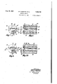
Fig. 1 is a longitudinal cross-sectional view of a post-mixed desurfacing nozzle exemplifying the invention;
Fig. 2 is an enlarged view in front elevation of the discharge end of the nozzle, part of the end Fig. 5 is a. view similar to Fig. 2 of a, modification for deseaming;
Fig. 6 is a reduced fragmentary sectional view taken on line 6-6 of Fig. 5; Y
Fig. 7 is an enlarged view in front elevation of a modification in whicha plurality of grooves are provided on the end face of the nozzle body for the acetylene slots, a, portion of the end cap of the nozzle being broken away to show the end face of the body member;
Fig. 8 is a view in longitudinal cross section of the modification shown in Fig. 7;
Fig. 9 is a view in front elevation of the discharge end of a one-piece post-mixed nozzle embodying features of the invention; and
Fig. 10 is a longitudinal cross-sectional view of the one-piece nozzle shown in Fig. 9.
As shown in Figs. 1 through 4 of the drawing, a desurfacing nozzle II) is provided which comprises an elongated generally tubular body or member II having a central cutting oxygen passage .l2 extending longitudinally therethrough. The central oxygen passage I2 is preferably of the shape vshown and claimed in Patent No. 2,267,623, and includes an inlet portion I3 of constant diameter, a ared portion I 4, a short portion I6 of constant diameter and a single outlet portion I 'I which gradually changes from circular to oblate or flat cross section, the discharge end of the central oxygen passage I2 being oblong as shown at I8. This causes the central oxygen passage I2 to discharge a characteristic desurfacing oxidizing gas stream which is well-known to those skilled in the art. The oxygen is discharged from the single outlet I8 in the form ofA a single solid or compact stream as distinguished from a tubular stream or a plurality of parallel streams. The tubular body II is also provided with a plurality of acetylene passages I9 arranged in spaced substantially parallel relation to the oxygen passage I 2, all of the passages I2 and I9 terminating in an end face 20 of the member II which lies in a plane disposed at right angles to the longitudinal axis of the member II.
The gas inlet end of the tubular body II is provided with a pair of radially and longitudinally spaced frusto-conical annular seats 2| and 22 which are adapted to mate with corresponding seats in a conventional head '(not shown) of a tudinal slots 24 for receiving tongues (not shown) for locating the nozzle III in proper position with respect to the blowpipe head. The nozzle IIJ is coupled to the blowpipe head in the usual way so that acetylene is delivered to the acetylene passages I9 and oxygen is delivered to the central oxygen passage l2. l
The tubular body Il is provided with a cylindrical end portion 25 of reduced diameter between the end face 20 and an annular shoulder 26. Mounted on such end portion 25 is an end cap 21 having a. cylindrical skirt 28 fitting such end portion, the edge of the skirt being bronze welded or silver soldered at 29 .to the shoulder 26 to secure the cap 28 and body member II in assembled relation. The cap 21 includes a bottom panel 30 having a shoulder 3I seated on the end face 28 to space the inner surface 32 of the panel 30 at a fixed distance from the face 20. The shoulders 3| are shaped so as to provide with the nozzle end face 20 a. senil-circular chamber or slot 32' around the discharge ends 33 of each group of acetylene passages I9, there being three such acetylene passages above and three below the oxygen orifice I8 in the present example.
The bottom panel 30 of the cap 21 has a transverse opening 34, the inner parallel edges 35 of which are laterally offset with respect to or spaced farther apart than the inner parallel edges 3-6 of the discharge end I8 of the central oxygen passage I2. The orifice I8 of the oxygen passage is also provided with a peripheral recess or groove 31. The recess 31 causes eddy currents on the surface layer of the single discharging oxygen stream and thus provides a fringe of low velocity oxygen around the otherwise unbroken or solid stream of oxygen, for admixture with the acetylene, to form a post-mixed preheating flame, when the oxygen stream is discharged at a desurfacing velocity; and prevents such flame being blown out, With this arrangement, acetylene flowing through the acetylene passages I9 into chambers 32 is discharged as two thin wide streams from chambers 32' and directed inwardly against the wide upper and lower sides of the single oblong stream of oxygen discharged by the central passage I2 immediately after the oxygen stream leaves the discharge orifice of the passage I2. In some cases, only one acetylene passage I9 might be provided instead of three at each side of the oxygen passage, and also acetylene might be fed against only one side of the discharging oxygen stream, preferably the upper side.
In operation, oxygen is first supplied to the central oxygen passage I2 only in sufficient volume and pressure to mix with the acetylene discharged by the parallel outlets 38 of chambers 32 above and below the slotted oxygen orifice I8 :to produce an externally mixed Oxy-acetylene flamel for heating the work to start the desurfacing operation when the velocity of the oxygen stream is subsequently increased. The velocity of the-central oxygen stream discharged by the orifice I8 is then increased to a desired value (depending upon the nature of the operation to be performed, in this case to a` desurfacing velocity) without altering the quantity of acetylene supplied to the nozzle and discharged against both sides'of the oxygen stream. The desurfacing oxygen stream is thereby provided at each of its flat surfaces with a preheating flame composed of a mixture of oxygen and acetylene which is mixed externally of the nozzle, owing to the unique construction of the working end of the nozzle. Iron powder or the like may of course be supplied to the oxygen or acetylene before it enters the nozzle, or as it flows through the nozzle, or after it is discharged from the nozzle, for the purpose of starting the reaction with iron bodies or for continuously carrying on the reaction with oxidation resistant bodies.
Referring to Figs. 5 and 6 there is shown a deseaming nozzle 4I) of somewhat similar construction to that described above in connection with Figs. 1 to 4, with the exception that the discharge end 4I of the central oxygen passage 42 is round, the opening 43 in the end cap 44 also being round and coaxial with but radially offset with respect to the inner edge of the discharge end of the oxygen passage 42. Another difference is that the acetylene passages 45 are arranged in a circle y about and concentric with the central oxygen passage 42, and an integral annular shoulder 46 is provided on the end face 41 of the tubular nozzle body 48, to space the inner surface 49 of the bottom panel 30' of the cap 44 away from the end face 41 of the tubular body 48 of the nozzle 4I). In such case, the bottom panel 50 is of uniform thickness and of even less expensive construction than that of the cap 21. In some cases, the shoulder might be entirely omitted from the cap or end of the nozzle by utilizing the length of the skirt on the cap to space the inner surface of the bottom panel of the cap at a predetermined distance from the end face of the body portion. In the nozzle 40 a recess corresponding to recess 31 of nozzle I0 is omitted, but may be used if desired or necessary depending upon the velocity of the cutting oxygen stream.
In the operation of the deseaming nozzle shown in Figs. 5 and 6, after the work has been preheated by a preheating flame produced by supplying oxygen at a relatively low velocity to the passage 4'2 while supplying acetylene through the acetylene passages 45 into the annular chamber 45 and thence radially inwardly as an annular jet against the issuing oxygen stream, the velocity of the oxygen flowing through the passage 42 is increased to a deseaming velocity without changing the quantity of acetylene supplied to the passagesv 45 and discharged inwardly from the chamber 45'. In this case the central stream of oxygen discharged by the nozzle 40 is surrounded by an oxyacetylene preheating flame which is mixed externally of the nozzle, the arrangement being such that the flame continues to burn at the increased velocity of the oxygen.
In some cases the post-mixed nozzles shown in Figs. 1 to 6 of the drawings are subject to a disadvantage in that the narrow acetylene outlets from which the acetylene is discharged inwardly against the sides of the solid stream of oxygen are apt to be changed in width or closed either by expansion ofthe metal or by mechanical abuse of the end panels of the caps. Such disadvantage is overcome by the modifications shown in Figs. '1 and 8 in which the bottom panel of the cap engages and is supported by the end face of the tubular body, especially in the areas along the edge of the opening in the bottom panel.
Referring to Figs. '1 and 8, there is shown a blowpipe nozzle comprising a tubular body 6I having a central oxygen passage 62 extending longitudinally therethrough, and also having a plurality of acetylene passages 63 arranged in spaced relation to the oxygen passage 62. The discharge ends of the passages 62 and 63 termiend cap 65 having a cylindrical skirt fits the annular end portion of the tubular body, and is secured in place on such memberwith the bottom panel 65 of the cap in supporting relation with the end face 6l of the member 6|. The bottom panel 65 is provided with an opening 66 the inner edges of which are laterally offset with respect to the discharge end 6l of the oxygen passage 62. The discharge end 61 of theroxygen passage has a peripheral recess 68 and is entirely open for discharging only a single solid stream of oxygen. The end face 64 of the body member 6i is providedwith a plurality of parallel grooves 89 disposed so as to direct the acetylene discharged by the acetylene passages '63 inwardly toward the single stream of oxygen as the latter leaves the discharge end of the oxygen pas-sage B2. The grooves 69 are of rectangular cross section so as to provide acetylene slots which discharge the acetylene inwardly against the oxygen stream as it leaves the oxygen passage, there being a groove or slot 6B for each acetylene pas- Since the bottom panel of the cap engages the end face 64 of the body between' the grooves 69, however, the arrangement is such that it is impossible for the panel to close the grooves 69 du to warpage or other injury.
The modification of the invention shown in Figs. 9 and 10 consists of a one-piece nozzlelli) having a central oxygen passage 8| and a plurality of acetylene passages 82 all of which terminate in a common plane 83. The tubular nozzle 80 'is provided withan oblong opening 84 the inner longitudinal edges of which are laterally offset with respect to the corresponding edgesV of the oblong discharge end 85 of the oxygen passage 8I in the plane 83. The nozzle has a periph` y ber or slot 81 atl each side of the recess 86, each chamber being disposed so as to direct the acetfires or flashbacks which are inherent in blowpipe apparatus which utilizes premixed oxygen and acetylene to produce the preheating flames.
1. A blowpipe nozzle comprising an elongated member having a central oxygen passage extending longitudinally therethrough and also having a plurality o f acetylene passages arranged in spaced substantially parallel relation to said oxygen passage, the discharge ends of all of said passages terminating in one end of said member having a face lying in a plane disposed at right angles to the longitudinal axis of said member; an end cap having a cylindrical skirt iltting an annular end portion of said member, the bottom panel of said cap having a shoulder seated on said end face to space the inner surface of said panel a fixed ,distance from said face, and` means securing said cap in place on said member, said cap also having a bottom panel provided with an and being entirely open for discharging only a ylene discharged by the corresponding group of acetylene passages82 inwardly against the single stream of oxygen as the latter leaves the discharge end 85 of the oxygen passage.L The discharge ends 88 of the acetylenepassages 82 are ararnged in rows, as shown, parallel to the longitudina ledges of the opening 84, and the' wide such case the end cap servesnot onlyto protect the end of the body member from wear and damage in use but also servesto direct the acetylene toward the oxygen oriceof. the nozzle.
It will be appreciated by those skilled in the art that the present` invention includes the use of standard parts which are readily available, and produces an oxidizing gas stream `and a preheating flame simultaneously Withoutdanger of backsingle stream 'of oxygen, and said bottom panel being disposed so as to direct the acetylene discharged by said acetylene passages inwardly toward said single stream of oxygen as the latter leaves the discharge end'of said oxygen passage.
2. A blowpipe nozzle comprising an elongated member having a central oxygen passage extending longitudinally therethrough and also having a plurality of fuel gas passages arranged in spaced relation to said oxygen passage, the discharge ends of all of said passages terminating in an end face of said member, an end cap having a cylindrical skirt fitting an annular end portion of said member, said cap also having a bottom panel, means spacing an inner surface portion of said bottom panel a fixed distance from said end face; and means securing said cap in place onV said member, the? bottom panel of said cap having an opening the edge of which is laterally offset with respect to the edge of the dischargeend of said oxygen passage, said discharge. end of the oxygen passage having a lateral recess and being entirely open for discharging only a single stream of oxygen having a fringe of lower velocity than that of the inner part, and said bottom panel being disposed so as to direct the fuel gas discharged by said fuel gas passages inwardly toward said single stream of oxygen as the latter leaves the `discharge end of said oxygen passage.
3. A blowpipe nozzle as `claimed by claim 2, in which saiddischarge end of said oxygen -passage is oblong in cross section, and said opening in said bottom panel of said end cap is also oblong,
whereby a fiat but solid stream of oxygen suit- 5. A blowpipe nozzle comprising a member having an oxygen passage extending therethrough and also having a fuel gas passage arranged in spaced relation to said oxygen lpassage, the discharge end of each of said passages terminating in a portion-of an end face of said member, an end cap having a skirt fitting an end portion of said member, said cap also having a bottom panel, the inner surface of said bottom panel having a portion spaced a fixed distance from said end face portion; and means securing said cap in 'place on said member, the bottom panel of said cap having an opening the edge of which is laterally offset with respect to the edge of the disto the wide side of said oblong discharge end of said oxygen passage.
10. A desurfacing blowpipe nozzle comprising an elongated member having a longitudinally disposed oxygen passage terminating in oblong stepped orifices at one end of said member, said member also having a longitudinally disposed fuel-gas passage terminating in such end of said member, and an end cap secured to such end of said member, said cap having an oblong opening axially aligned with said oxygen passage, said cap also having panel means in line with said fuel-gas passage for defiecting the gas discharged thereby substantially perpendicularly toward only one side of said oblong opening, and means providing a space communicatively connecting the fuel-gas passage with the oblong opening.
11. A post-mixed desurfacing blowpipe nozzle having a single oblong discharge orifice and an oxygen supply passage axially in line with such orifice, said nozzle also having fuel gas supply passages and two fuel gas chambers, said chambers opening into two opposite sides of such oxy- 6. A blowpipe nozzle comprising an elongated member having a central oxygen passage extending longitudinally therethrough and also having acetylene passage means arranged in spaced relation to said oxygen passage, the discharge ends of all of said passages terminating in an end face of said member, an end cap having a cylindrical skirt fitting an annular end portion of said member, and means securing said cap in place on said member with the bottom panel of said cap in supporting relation with the end face of said member, said bottompanel being provided with an opening, the inner edge of which is latf erally offset with respect to the edge of the discharge end of said oxygen passage, said discharge end of the oxygen passage having a peripheral recess and being entirely open for discharging only a single stream of oxygen, and said end face being provided with a plurality of grooves of rectangular cross section disposed so as to direct the acetylene discharged by said acetylene passage means inwardly toward said single stream of oxygen as the latter leaves the discharge end of said oxygen passage.
'7. A blowpipe nozzle as claimed by claim 6, in which said grooves are flat so as to provide acetylene slots which introduce the acetylene to .the oxygen stream as it leaves said oxygen passage. 1
8; A blowpipe nozzle comprising a tubular member having a central oxygen passage extending longitudinally therethrough and also having acetylene passage means arranged in spaced relation to said oxygen passage, the discharge ends of all of said passages terminating in a'common plane,.said tubularmember being provided with an opening the inner edge of which is laterally offset with respect to the edge of the discharge end of said oxygen passage in said plane, said discharge end of the oxygen passage having a peripheral recess and being entirely open for discharging a single stream of oxygen, and said member being provided with an acetylene slot disposed so as to direct the acetylene discharged by said acetylene passage means inwardly toward said single stream of oxygen as the latter leaves said discharge end of said oxygen passage.
9. A blowpipe nozzle as claimed by claim 8, in which said acetylene slot is flat, said discharge end of said oxygen passage is oblong in cross section, and the wide side of said fiat slot is parallel gen passage through narrow elongated slots parallel to the longer axis of such orifice. said orice being Wider than the adjacent end of said oxygen supply passage the construction and arrangement being such that, when the nozzle is disposed in operating position with the longer axis of such orifice parallel to the work surface and a preheating oxygen stream of low velocity is discharged therethrough, two wide streams of fuel gas will be discharged from such narrow slots against the top and bottom sides of the oxygen stream, to produce wide and extended streams of combustible mixture for work preheating, and. when the velocity of the oxygen stream is increased for desurfacing, the two wide fuel streams will continue to impinge against the top and bottom sides of the oxygen stream as before, to produce even more extended heating flames for assisting the desurfacing operation as it advances. 12. A blowpipe nozzle comprising means having a passage for discharging a stream of cutting oxygen from the nozzle, and means having a way for feeding fuel gas against the periphery of said cutting oxygen stream as said cutting oxygen stream leaves said passage, said passage having an outlet end, and means providing a lateral recess located directly downstream of said outlet end, said recess communicating with and cooperating with said way and outlet end so that a combustible mixture of oxygen and fuel gas is formed adjacent said cutting oxygen stream outside of the nozzle.
13. A blowpipe nozzle having a cutting oxygen passage the outlet end of which is open for discharging a stream of cutting oxygen, said nozzle having a lateral recess adjacent the outlet end of said cutting oxygen passage, and said nozzle also having a fuel, gas passage the outlet end of which opens at an angle to one side of such recess at the outlet end of said cutting oxygen passage, whereby when cutting oxygen is delivered to said oxygen passage at a relatively low velocity, such oxygen mixes with the fuel gas discharged from the outlet end of said 'fuel gas passages to form an externally mixed oxy-fuel gas ame, and, when the velocity of said cutting oxygen is increased, while the velocity of the fuel gas remains constant, only a portion of the discharged oxygen mixes with the fuel gas, thereby 'forming an externally mixed flame beside the cutting oxygen stream which flame is stable by virtue of said recess. I
' spaced from said oxygen passage and a portion shorter than said longitudinal portion and extending toward the axis of said single oxygen discharge passage, suchl shorter portion of said fuel gas passage having a fuel gas discharge opening disposed forwardly of and radially outwardly of said single oxygen discharge .passage to discharge fuel gas inwardly against the external surface of said single oxygen stream immediately after said oxygen stream issues from said single oxygen discharge orifice, to mix the low velocity fringe of Oxygen adjacent said oxygen stream with the issuing fuel gas to produce a preheating gas `mixture and flame adjacent said" oxygen stream after both said single oxygen stream and the fuel gas have discharged from said oxygen passage and said fuel gas passage, respectively.
15. An elongated blowpipe nozzle having a 1on-A gitudially extending cutting oxygen passage terminating in an enlarged entirely open outlet portion, said nozzle also having a plurality of fuel gas passages terminating at said enlarged outlet portion of said oxygen passage, and said nozzley having a single common outlet opening for the oxygen and fuel gas discharged by such passages, which common outlet opening is laterally enlarged with respect to the enlarged outlet portion of said oxygen passage.
16. A blowpipe nozzle comprising a. body having an unrestricted axially extending cutting oxygen passage and a longitudinally extending fuel gas passage, a cap non-adjustably secured to the outlet end of said body and having an opening in line with said cutting oxygen passage, said cap and body being internally shaped at the outlet end of said fuel gas passage to provide a f fuel gas chamber -near the outlet end of the nozzle, the cap and body also being internally shaped to provide said chamber with a fuel gas portlaterally facing the cutting oxygen passage, the opening in said cap being radially offset with respect such cutting oxygen passage to insure mixing of the fuel gas and oxygen discharged from said port and cutting oxygen passage.
17. A blowpipe nozzle having an unrestricted axially extending cutting oxygen passage and a l0 longitudinally extending fuel gas passage, said nozzle having a fuel gas chamber in communicaf, tion with said fuel gas passage and located near the outlet end of the nozzle, said nozzle also having a fuel gas port connected to sai`d chamber and laterally facing the cutting oxygen passage, the downstream section of the passage being radially olset with respect to the upstream section of such cutting oxygen passage adjacent said port, to insuremixing of the fuel gas and oxygen discharged from said port and cutting oxygen passage.
JAMES H. BUCKNAM. IVAN P. THOMPSON.
REFERENCES CITED The following references are of record in the file of this patent:
UNITED STATES PA'I'ENTS Number Harris July 29,l Miller Oct. 1, 1929 Scheller ..-l July 21, 1942 Hendricks May 8, 1934 FOREIGN PATENTS g Country Date France .Nov. 19, 1926 Germany June 4, 1918 France May 3, 1937 Switzerland Feb. 17, 1936 Germany May 31, 1919 Austria Aug.,25, 1920 Number Kehl NOV. 28, 19394
Priority Applications (1)
| Application Number | Priority Date | Filing Date | Title |
|---|---|---|---|
| US478202A US2425709A (en) | 1943-03-06 | 1943-03-06 | Blowpipe nozzle |
Applications Claiming Priority (1)
| Application Number | Priority Date | Filing Date | Title |
|---|---|---|---|
| US478202A US2425709A (en) | 1943-03-06 | 1943-03-06 | Blowpipe nozzle |
Publications (1)
| Publication Number | Publication Date |
|---|---|
| US2425709A true US2425709A (en) | 1947-08-19 |
Family
ID=23898938
Family Applications (1)
| Application Number | Title | Priority Date | Filing Date |
|---|---|---|---|
| US478202A Expired - Lifetime US2425709A (en) | 1943-03-06 | 1943-03-06 | Blowpipe nozzle |
Country Status (1)
| Country | Link |
|---|---|
| US (1) | US2425709A (en) |
Cited By (10)
| Publication number | Priority date | Publication date | Assignee | Title |
|---|---|---|---|---|
| US2510210A (en) * | 1944-05-26 | 1950-06-06 | Linde Air Prod Co | Method of thermochemically cutting metal bodies |
| US2582946A (en) * | 1948-06-21 | 1952-01-22 | Warren E Brill | Flame method of cutting metal |
| US2655988A (en) * | 1947-05-24 | 1953-10-20 | Daniel A Marra | Gas torch tip having protective terminal shoe |
| US3000435A (en) * | 1950-04-28 | 1961-09-19 | Selas Corp Of America | Furnace burner |
| US3141615A (en) * | 1961-12-18 | 1964-07-21 | Lowndes Engineering Company In | Process and apparatus for producing a fog |
| US3750957A (en) * | 1970-09-19 | 1973-08-07 | Messer Griesheim Gmbh | Torch for thermochemical processing of work pieces |
| US3928084A (en) * | 1974-06-07 | 1975-12-23 | Berwyn E Etter | Tip for an industrial gas cutting torch and method of using same |
| US4145000A (en) * | 1977-01-14 | 1979-03-20 | Smith Fergus S | Snow-making nozzle assembly |
| US5456415A (en) * | 1994-04-07 | 1995-10-10 | Gardner; James J. | Atomizing nozzle for liquids |
| US20110239872A1 (en) * | 2008-11-06 | 2011-10-06 | Shojiro Saito | Foaming nozzle |
Citations (16)
| Publication number | Priority date | Publication date | Assignee | Title |
|---|---|---|---|---|
| DE300705C (en) * | ||||
| DE305928C (en) * | ||||
| US1311815A (en) * | 1919-07-29 | Blowpipe-buhner | ||
| AT81165B (en) * | 1915-04-29 | 1920-08-25 | Autogen Werke Fuer Autogene Sc | Daniell's cock for separate feed. BreDaniell's cock for separate feed of fuel and oxygen or air. fuel and oxygen or air. |
| FR617256A (en) * | 1925-10-20 | 1927-02-16 | Air Liquide | Acetylene or similar gas cutting torch |
| US1729677A (en) * | 1929-10-01 | Gas burner | ||
| US1958044A (en) * | 1930-12-08 | 1934-05-08 | Edward H Hendricks | Torch for removing defects from billets |
| CH181091A (en) * | 1934-07-16 | 1935-11-30 | Manz Dietrich Fritz | Burner head for a device for removing crusts of all kinds on heating surfaces of steam boilers, boilers and the like. |
| FR817708A (en) * | 1936-01-07 | 1937-09-09 | Air Liquide | Method of operation of torches for working underwater and torch for carrying out this method |
| US2100384A (en) * | 1932-09-29 | 1937-11-30 | Air Reduction | Oxygen cutting apparatus |
| US2148936A (en) * | 1935-01-12 | 1939-02-28 | Union Carbide & Carbon Corp | Flame machining nozzle |
| US2181135A (en) * | 1933-08-10 | 1939-11-28 | Union Carbide & Carbon Corp | Multiple flame nozzle |
| US2210402A (en) * | 1937-02-27 | 1940-08-06 | Linde Air Prod Co | Method of removing metal from metallic bodies |
| US2286591A (en) * | 1940-03-30 | 1942-06-16 | William Van Triest | Method of scarfing |
| US2290295A (en) * | 1940-11-08 | 1942-07-21 | Linde Air Prod Co | Method and apparatus for desurfacing metal |
| US2294392A (en) * | 1939-01-14 | 1942-09-01 | Linde Air Prod Co | Blowpipe nozzle |
-
1943
- 1943-03-06 US US478202A patent/US2425709A/en not_active Expired - Lifetime
Patent Citations (16)
| Publication number | Priority date | Publication date | Assignee | Title |
|---|---|---|---|---|
| DE305928C (en) * | ||||
| US1311815A (en) * | 1919-07-29 | Blowpipe-buhner | ||
| US1729677A (en) * | 1929-10-01 | Gas burner | ||
| DE300705C (en) * | ||||
| AT81165B (en) * | 1915-04-29 | 1920-08-25 | Autogen Werke Fuer Autogene Sc | Daniell's cock for separate feed. BreDaniell's cock for separate feed of fuel and oxygen or air. fuel and oxygen or air. |
| FR617256A (en) * | 1925-10-20 | 1927-02-16 | Air Liquide | Acetylene or similar gas cutting torch |
| US1958044A (en) * | 1930-12-08 | 1934-05-08 | Edward H Hendricks | Torch for removing defects from billets |
| US2100384A (en) * | 1932-09-29 | 1937-11-30 | Air Reduction | Oxygen cutting apparatus |
| US2181135A (en) * | 1933-08-10 | 1939-11-28 | Union Carbide & Carbon Corp | Multiple flame nozzle |
| CH181091A (en) * | 1934-07-16 | 1935-11-30 | Manz Dietrich Fritz | Burner head for a device for removing crusts of all kinds on heating surfaces of steam boilers, boilers and the like. |
| US2148936A (en) * | 1935-01-12 | 1939-02-28 | Union Carbide & Carbon Corp | Flame machining nozzle |
| FR817708A (en) * | 1936-01-07 | 1937-09-09 | Air Liquide | Method of operation of torches for working underwater and torch for carrying out this method |
| US2210402A (en) * | 1937-02-27 | 1940-08-06 | Linde Air Prod Co | Method of removing metal from metallic bodies |
| US2294392A (en) * | 1939-01-14 | 1942-09-01 | Linde Air Prod Co | Blowpipe nozzle |
| US2286591A (en) * | 1940-03-30 | 1942-06-16 | William Van Triest | Method of scarfing |
| US2290295A (en) * | 1940-11-08 | 1942-07-21 | Linde Air Prod Co | Method and apparatus for desurfacing metal |
Cited By (11)
| Publication number | Priority date | Publication date | Assignee | Title |
|---|---|---|---|---|
| US2510210A (en) * | 1944-05-26 | 1950-06-06 | Linde Air Prod Co | Method of thermochemically cutting metal bodies |
| US2655988A (en) * | 1947-05-24 | 1953-10-20 | Daniel A Marra | Gas torch tip having protective terminal shoe |
| US2582946A (en) * | 1948-06-21 | 1952-01-22 | Warren E Brill | Flame method of cutting metal |
| US3000435A (en) * | 1950-04-28 | 1961-09-19 | Selas Corp Of America | Furnace burner |
| US3141615A (en) * | 1961-12-18 | 1964-07-21 | Lowndes Engineering Company In | Process and apparatus for producing a fog |
| US3750957A (en) * | 1970-09-19 | 1973-08-07 | Messer Griesheim Gmbh | Torch for thermochemical processing of work pieces |
| US3928084A (en) * | 1974-06-07 | 1975-12-23 | Berwyn E Etter | Tip for an industrial gas cutting torch and method of using same |
| US4145000A (en) * | 1977-01-14 | 1979-03-20 | Smith Fergus S | Snow-making nozzle assembly |
| US5456415A (en) * | 1994-04-07 | 1995-10-10 | Gardner; James J. | Atomizing nozzle for liquids |
| US20110239872A1 (en) * | 2008-11-06 | 2011-10-06 | Shojiro Saito | Foaming nozzle |
| US8960080B2 (en) * | 2008-11-06 | 2015-02-24 | Ss&W Japan | Foaming nozzle |
Similar Documents
| Publication | Publication Date | Title |
|---|---|---|
| US2425709A (en) | Blowpipe nozzle | |
| US4455176A (en) | Post-mixed oxy-fuel gas cutting torch and nozzle and method of oxy-fuel gas cutting | |
| US2353318A (en) | Nozzle for desurfacing metal | |
| US2210402A (en) | Method of removing metal from metallic bodies | |
| US5700421A (en) | Cutting nozzle assembly for a postmixed oxy-fuel gas torch | |
| US4468007A (en) | Oxy cutting torch | |
| US2378346A (en) | Apparatus for mixing and burning fuel | |
| US6277323B1 (en) | Cutting nozzle assembly for a postmixed oxy-fuel gas torch | |
| US2425710A (en) | Blowpipe nozzle | |
| US5535953A (en) | Injector tip for burning aggregates | |
| GB1425367A (en) | Flat-flame burner utilising heavy liquids fuels | |
| US2380570A (en) | Blowpipe nozzle | |
| US2365411A (en) | Deseaming apparatus | |
| US2614616A (en) | Gas mixing method and blowpipe apparatus | |
| US3674213A (en) | Cutting head for thermochemical machining | |
| US1907604A (en) | Oxyacetylene and similar heating burner | |
| US3510064A (en) | Oxy-fuel flame burner nozzles | |
| US2365942A (en) | Torch | |
| US3750958A (en) | Burner nozzle | |
| US3172457A (en) | Apparatus for thermochemical scarfing | |
| US4184637A (en) | Oxygen-fuel cutting torch | |
| US2396765A (en) | Torch | |
| US2456784A (en) | Blowpipe apparatus | |
| US2654329A (en) | Blowpipe employing adjuvant powder for thermochemically removing material | |
| US2433539A (en) | Blowpipe nozzle |