US2424872A - Convertible flat-bed and cylinderarm sewing machine - Google Patents
Convertible flat-bed and cylinderarm sewing machine Download PDFInfo
- Publication number
- US2424872A US2424872A US568405A US56840544A US2424872A US 2424872 A US2424872 A US 2424872A US 568405 A US568405 A US 568405A US 56840544 A US56840544 A US 56840544A US 2424872 A US2424872 A US 2424872A
- Authority
- US
- United States
- Prior art keywords
- bed
- work
- arm
- base
- machine
- Prior art date
- Legal status (The legal status is an assumption and is not a legal conclusion. Google has not performed a legal analysis and makes no representation as to the accuracy of the status listed.)
- Expired - Lifetime
Links
- 238000009958 sewing Methods 0.000 title description 32
- 230000015572 biosynthetic process Effects 0.000 description 3
- NJPPVKZQTLUDBO-UHFFFAOYSA-N novaluron Chemical compound C1=C(Cl)C(OC(F)(F)C(OC(F)(F)F)F)=CC=C1NC(=O)NC(=O)C1=C(F)C=CC=C1F NJPPVKZQTLUDBO-UHFFFAOYSA-N 0.000 description 2
- 229920000136 polysorbate Polymers 0.000 description 2
- 210000002105 tongue Anatomy 0.000 description 2
- 241001300059 Theba Species 0.000 description 1
- 150000001412 amines Chemical class 0.000 description 1
- 238000010276 construction Methods 0.000 description 1
- 238000004519 manufacturing process Methods 0.000 description 1
- 239000000463 material Substances 0.000 description 1
- 239000002184 metal Substances 0.000 description 1
- 230000000717 retained effect Effects 0.000 description 1
- 230000000630 rising effect Effects 0.000 description 1
Images


Classifications
-
- D—TEXTILES; PAPER
- D05—SEWING; EMBROIDERING; TUFTING
- D05B—SEWING
- D05B73/00—Casings
-
- D—TEXTILES; PAPER
- D05—SEWING; EMBROIDERING; TUFTING
- D05B—SEWING
- D05B73/00—Casings
- D05B73/04—Lower casings
- D05B73/10—Devices for converting free-arm sewing machines into flat-bed machines
-
- D—TEXTILES; PAPER
- D05—SEWING; EMBROIDERING; TUFTING
- D05B—SEWING
- D05B77/00—Covers, or portable enclosures, for sewing machines
Definitions
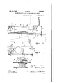
- CONVERTIBLE FLAT-BED mo CYLINDER-ARM SEWING. mourns Filed Dec. 16,1944 4 Sheets-Sheet 4 3 Sydney ywy f z Patented July 29, 1947 CONVERTIBLE- FLAT-BED AND CYLINDER- ARM SEWING MACHINE Sydney Zonis, Bridgeport, Conn, assignor to The Singer Manufacturing? Company,
- This invention relates to sewing machines and more particularly to a sewing machine which may be readily changed from a flat-bed machine, used for general sewing purposes, tov a cylinderarm or bed machine.
- a primary object of this invention is to provide a sewing machine which is quickly andjeasily convertible for use either as a flat-bed type sewing machine having work-feeding mechanism of the drop-feed type or as a cylinder work-arm type sewing machine in which the minimum size of the free end portion of the work-arm is limited solely by loop-taker mechanism which is complemental to the sewing machine needle in the,
- This invention has also for its object to provide a sewing machine having a detachable flat work-supporting bed underlying the brackets arm, which bed carries the work-advancing.
- Another object of this invention is to provide;-
- Another object of this invention is to provide improved latching means for holding the detachable portion of the flat bed in position when it is used as a work-support and tohold the machine on the detachable flat bed when it is used as a support for the stitch-forming mechanism,
- Another object of this invention is to provide the removable portion of the bed with end walls in which are journaled the feed-rock-shafts and to provide a feed-dog oflfset laterally from the feed-bar so as to overhang the end of the cylinder arm.
- the invention comprises the devices, combinations and arrangements of parts hereinafter set forth and illustrated in the accompanying drawings of a preferred embodiment of the invention, from which the several features of the invention and theadvantages 21 Claims.
- I (Cl. 112260) 2 attained thereby will be readily understood :by those skilled in the art.
- Fig. 1 is a front elevation of my improved combinational sewing machine showing the fiat work-supporting bed in operative position
- Fig. 2 is a front elevation of my improved machine showing the fiat bed removed for the purpose of converting the machine into a cylinder bed darning machine and the removable bed used as a support for the machine.
- Fig. 3 is a top plan view of the machine shown in Fig. 1 with the bracket-arm removed.
- Fig. 4 is a bottom plan view of the machine shown'in Fig. 1.
- Fig. 5 is a left end elevation of the cylindrical work-arm and base of the machine shown in Fig. 2.
- Fig. 6 is a detailed sectional view taken-along the line 6-6 of Fig. 4.
- Fig. 7 is a view taken along the line 1-l of Fig; 3.
- Fig. 8 is a sectional view taken along the line 8-8 of Fig. 4.
- Fig. 9 is a side elevation of the cylindrical arm with a central section through the fiat bed and feed-dog, showing the position of the feed-dog and its relation to the cylindrical arm and the flat bed.
- Fig.- 10 is a right end elevation of the removable fiat bed and Fig.-1l is an enlarged detail view showing the detachable connection between the rock-shaft in the bed and the actuating rockshaft in the :base.
- my improved convertible flatbed and cylinder-arm machine comprises'a base Ill having downturned side and end walls forming a rectangularly shaped enclosure.
- the bed Ill carries a laterally extending tubular shaped work-supporting arm II and a bracket-arm l2 terminating in a hollow head l3.
- a shaft I4 having a balance-wheel l5 secured to one of its ends. Th balance-wheel I5 is operatively connected by a belt Hi to an electric motor I! carried by the base l0.
- a crank I8 is secured to the other end of the shaft l4 and is connected by a link l9 to a needle-bar 20 journaled in the hollow head l3 and carrying an eye-pointed needle 2
- a gear 23 Fixed to the shaft I4 is a gear 23 which meshes with a gear 24 fixed to the upper end of a vertical shaft 25, and fixed to the lower end of the shaft 25 is a gear 26 which mesheswith a gear 21-;- secured upon a hook-shaft!!! journaled in a beer-"1: ing 29 formed on the base H3 (Fig. 4) and a 4 understood that with these connections when the rock-shafts 51 and 6B are oscillated about their longitudinal axis in the proper timed relation a four-motion feeding movement is imare :journaled-inand extend through the beari iiesi iLl-fBHn the wall- .5]; of the, lied 56.
- the shaft I4 Fixed to the shaft I4 is a gear 23 which meshes with a gear 24 fixed to the upper end of a vertical shaft 25, and fixed to the lower end of the shaft 25 is a gear 26 which mesheswith a gear 21-;- secured upon a hook-shaft
- each of the shafts 51 and 6B which bearing 30 in the work-supporting cylindrically.Cm-Ext s through i respecbiVe be is formed shaped arm H. 28 there is secured a rotary loop-taker? rotary hook lock-stitch type which is aida'pt To the other. end .ofthesha from the bobbin-case and engages aninwardly extending portion 34 formed on the endlwalliof I it he twa lls 13 with convergently inclined sides 10 terminating 'f iajlly extending tongue H (Fig.
- each of therock shaits 57 "and 60 has secured thereto a a sheet metal cap 35 which surround n h u 0 which enters a notch 11 formed in their respecthe; hoo 32 and isjsec ed to: .tewo se unnartr; ingarm H.
- J r e l ed t he haf l arej woj a c 1 11 which; are adapted to impart risin andfallingtivebear ngsSG. and BI (Figs. 4 and 6).
- the rob r fts"5 1 'a',hdf 6fl ,wm be retained in a pomdfeedaandletumzmovementsioftihe iteedihg 25 sitio'fr'ih"whichthefree' end of their extending mechan m. ,The 2 311 conn ted.
- The-bed50 is-also'-formed with a downwardly extending wal1'53,.arranged parallel-to the end wall 5
- Pins 8.6 will enter slots 88 and the foqtgpad g4 wi fhe raised above the level of the surfacejof lth g extension plate Bland resiliently ill tize itionh spring 8 r "to hold the bed 50', in the correct po- 4; tiv egjp theba'se [0.1 have provided latchesjlll and g1 made of spring strips and locateg onthgiljont,and back of the base I0.
- feed-dog 65' issecuredto the feed-bar and extends laterally from thetfeed-bar-fifto a ilfiwhich 'is' adapted to-turn about a horizontal pivfotepin gtjonrnaled in a suitable bearing in the hasem; "Eachof the latches so and a: has its free endrbent back upon itself toform a hook point-overlying the loop-taker 3i and into a po- 'andtheend's of Tthese latches are adapted to exsition; in which it extends through suitable slots inthe-'throat-plate -55t-and cooperates with a presser foot 3Bcarried by a presser-bar 3li'.-v The other-end obthe feed-bar 64- is pivotally secured.
- the bed 5!] is provided onv the work-supporting side thereof and in the region of the base it with upstanding rubber-feet I 5.
- the bed When the bed is inverted, it rests upon the foot-pads 84 and the rubber-feet I as illustrated in Fig. 2.
- the bed has front and rear feet NH and the base I0 has front and rear feet I03 whichare complemental to the feet IOI as a support for the machine as illustrated in Fig. 1.
- the base It When the bed is detached and inverted as above described, the base It) is placed thereupon so that the feet IUI of the bed enter circular apertures I02 provided in the base l0, and the feet I03 of the base I! enter apertures [94 formed in lugs provided on the side walls 52 of the bed 50.
- the arrangement produces an interlock between the bed '50 and the machine and prevents the machine-from shifting laterally relative to the bed when it is operated.
- as previously described, are pivotally supported and may be swung to a depending position in which they cooperate with lugs 99 and H10 formed on the side walls of the bed 50 to securely hold the machine on the bed.
- the throat-plate 55 on the bed 50 is spaced above the cap 35 on the arm II, the presser-foot 36 being adapted to rest on the throat-plate 55, and responding to upward movement of the feed-dog 65.
- the presser-foot 36 is held slightly above the upper surface of the cap 35 by the Dresser-bar 36 which is limited in its downward movement by any suitable means. This construction provides clearance between the presser-foot and the work-supporting arm for the shifting of the material during darning or other stitching operations.
- my improved machine may be readily converted from a fiat bed general purpose machine to a cylinder-bed machine.
- the fiat bed may be quicklyremoved to expose the cylinder-arm and that as the fiat-bed carries the feed-advancing mechanism it is removed from the machine with the bed.
- forms a support against tilting of the machine when pressure or weight is applied at the free end of the cylinder-arm; ample work space being provided beneath the arm II due to the inclined sides 82 of the extension plate.
- a sewing machine having in combination, a
- feed-actuating mechanism located within said base, a bed removably fitted over said arm and having a flat worbsupporting surface, a feed-bar and feed-dog carried by said bed, and means for operatively connecting said feed-bar with the feed-actuating mechanism within the base.
- a sewing machine having in combination, a bracket-arm terminating in a hollow head, a work-supporting arm underlying said bracketarm and having a free end terminating beneath said hollow-head, sewing instrumentalities including a needle carried by said head, a looptaker carried by said Work-supporting arm and cooperating with saidneedle, a bed overlying said work-supporting arm, said bed being provided with work-feeding mechanism, and means for detachably securing said bed to said machine whereby the bed and feeding mechanism may be removed as a unit.
- a sewing machine having in combination a laterally extending work-supporting arm, a looptaker carried by said arm, a flat work-supporting bed overlying said arm, four-motion feeding mechanism carried by said bed and arranged exteriorly of said arm, and means for detachlift and a feed-advance rock-shaft carried by said base, a Work-supporting arm extending there- 7 from, a bracket-arm carried by said base and said base and having loop-taking mechanism at bed, a feed-bar and feed-dog actuated by said last mentioned rock-shaft, and separable operative connections between the rock-shafts in said base and the rock-shafts carried by said bed.
- a sewing machine convertible from a flatbed machine to a cylinder arm machine comprising, a sewing machine having actuating mechanism and a tubular work-support in which a shaft carrying a loop-taker is j-ournaled, a fiat bed adapted to fit over said arm, said bed carrying work-advancing mechanism, means for detachably securing said bed to said machine, and means for operatively connecting the work-advancing mechanism in the bed with the actuating mechanism of the machine when the bed is fitted over the tubular work-support of the machine.
- a reciprocatory needle-bar journaled in said head and carrying an eye-pointed needle, means for reciprocating said needle, a rotary loop-taker housed within the free end portion of said work-arm and complemental to said needle in the formation of stitches, means for rotating said loop-taker, a flatbed work-support detachably secured upon said base, a feed-dog disposed externally of said workarm and operating through said work-support, and feed-dog actuating mechanism including separable connections in part journaled in said base and in part journaled in said fiat-bed worksupport.
- a sewing machine having in combination, a base, a bracket-arm carried by said base and terminating in a head, a reciprocatory eye-pointed needle carried by saidhea'd, loop-seizing means located below said head and cooperating with said needle in the formation of stitches, a removable flat bed secured to said base, and disposed be-' tween said head and loop-seizing means, and feeding mechanism carried by said base whereby said bed and feeding mechanism can be removed I 8 tween the rock-shafts in'the base and the rockshafts carried by said bed'.
- a sewing machine having in combination,
- a base a work supporting arm extending thereried by said bed, and latch means for releasably securing said bed to said base.
- a sewing machine having in combination, a base, a work-supporting arm extending therefrom, a bracket-arm carried'by said base and located above said work-supporting arm, actuating mechanism within said base including ockshafts, a detachable rectangularly shaped bed havingdepending walls andadapted to fit over said work-supporting arm to provide a fiat worksupporting surface, rock-shafts journaled in said bed and having their ends extending through one of said walls, andmeans connecting the ends of said rock-shafts wi'th the' rock-shafts in thebase.
- a sewing machine having in combination, a base, a work-supporting arm extending therefrom, abracket-arm; carried by said base and located above said work-supporting arm, actuating mechanism-within said base including rock-shafts, a detachable rectangularly shaped bed having depending walls and adapted-to fit over said worksupporting arm to provide a fiat work-supporting surface, rock-shafts journaled in said bed, means the bed about their longitudinal axes, whereby the rock-shafts in the bed are maintained in a position so that they may :be connected to the rock-shafts in the base in their correct radial position.
- a sewing machine having in combination, a
- a sewing machine having in combination, a base, a work-supporting arm extending therefrom, a bracket-arm carried by said base and located above said work-supporting arm, actuating mechanism within said base including rock-shafts, a detachable rectangularly shaped bed having depending walls and adapted to fit over said worksupporting arm to provide a fiat work-supporting surface, rock-shafts journaled in the walls of said bed, and detachable mechanical connections'befronija bracket-arm carried by said base and located above said work-supporting arm, actuating mechanism within said base including rockshaftsfa'detachable rectangularly shaped bed having depending walls and adapted to fit over said work-supporting arm to provide a flat worksupporting surface, rock-shafts journaled in the walls of said bed and detachably connected to the rock-shafts in said base, and a feed-bar having its ends operatively connected to the rock-shafts in the bed, said feed-bar being formed with an from, a bracket-
- a sewing machine having in combination, a base, a work-supporting arm extending therefrom, a bracket-arm carried by said base and located above said work-supporting arm, actuating mechanism within said base, a rectangularly shaped bed having depending side and end-walls forming an enclosure, said bed being adapted to fit over said work-supporting arm and to be detachably secured to said base to provide a flat work-supporting surface, rock-shafts journaled in said bed and having their ends extending through one of said walls, means detachably connecting the ends of said rock-shafts with the actuating mechanism in the base, a feed-bar actuated by said rock-shafts, and a feed-dog carried by's'aid feed-bar.
- a sewing machine having in combination, a base, a work-supporting arm extending therefrom, a bracket-arm carried by said base and located above said work-supporting arm, actuating mechanism within said base, a rectangularly shaped bed having depending side and endwalls forming an enclosure, said bed being detachably secured to said base and spaced above said work-supporting arm, rock-shafts journaled in said bed and having their ends extending through one of said walls, means detachably connecting the ends of said rock-shafts with the actuating mechanism in the base, a feed-bar actuated by said shafts and having an offset portion to provide clearance for the free end of the work-supporting arm, and a feed-dog carried by said feed-bar and extending into the space between the bed and the work-supporting arm.
- a sewing machine adapted to be converted from 'a'fiat-bed machine to a darning machine and having incombination, a base, a work-supporting arm extending therefrom, a bracket-arm carried by said base and located above said worksupporting arm, a rectangularly shaped bed having depending side and end-walls forming an enclosure, saidbed being removably fitted over said work-supporting arm and detachably secured thereto to provide a readily removable fiat worksupporting surface, and supporting means located on the bottom of said bed and adapted to cooperate with the base of said machine whereby the fiat bed may be removed from the machine and used in an inverted form as a pedestal to support the darning machine.
- a sewing machine adapted to be converted from a flat-bed machine to a, cylinder bed darning machine and having in combination, a base, a work-supporting arm extending therefrom, a bracket-arm carried by said base and located above said work-supporting arm, a rectangularly shaped bed having depending side and end-walls and adapted to fit over said Work-supporting arm to provide a flat work-supporting surface, said bed being removably secured to said base, an extension plate pivotally secured to said bed, and means carried at an edge of the side and end walls of said bed for supporting said base, whereby the flat bed may be removed from the machine and used in an inverted form as a pedestal for the darning machine with the extension plate on the base located beneath the work-supporting arm.
- a sewing machine having in combination a bracket-arm terminating in a hollow head, a work-supporting arm underlyin said bracketarm and having a free end terminating beneath said hollow head, stitch forming devices including loop-taker actuating mechanism disposed within and extending lengthwise of said worksupporting arm, a bed removably fitted over said work-supporting arm, work feeding mechanism for advancing work crosswise of said arm, said work feeding mechanism including a four-motion feed-dog disposed externally of said arm and operating through said bed, and feed-dog actuating connections extending lengthwise of said Work-supporting arm.
- a convertible sewing machine having in combination a laterally extending work-supporting arm, a loop-taker carried by said arm, a removable flat Work-supporting bed adapted to fit over said arm to form a flat work supporting surface, a work-advancing feed-dog disposed externally of said arm and operating through said bed, substantially parallel feed-advance and feed-lift rock-shafts each comprising endwise separable shaft sections, means for actuating said rock-shafts, and operable connections with sections of said rock-shafts remote from said means for actuating said feed-dog.
Description
July 29,1947. im 2,424,872
. CONVERTIBLE FLAT-BED AND CYLINDER-ARM SEWING MACHINE" Filed Dec. 16, 1944 4 Sheets-Sheet l Z05 gvwewto u Witww$= 5 V y 3 3014/56 W W W July 29, 1947.
s. zoms CONVERTIBLE FLAT- BED AND CYLINDER-ARM SEWING MACHINE Filed Dec. 16, 1944 4 Sheets-Sheet 2 Wi/meow S. ZONIS Jul 29, 1947.
CONVERTIBLE FLAT-BED AND CYLINDER-ARM SEWING MACHINE Filed Dec.. 16, 1944 4 shee ts-she-fi-t 3 Snow/m Sydngy 591/068 I Wihleam %W I July 29, 1947. s zoms 2,424,872
CONVERTIBLE FLAT-BED mo CYLINDER-ARM SEWING. mourns Filed Dec. 16,1944 4 Sheets-Sheet 4 3 Sydney ywy f z Patented July 29, 1947 CONVERTIBLE- FLAT-BED AND CYLINDER- ARM SEWING MACHINE Sydney Zonis, Bridgeport, Conn, assignor to The Singer Manufacturing? Company,
Elizabeth,
N. J a corporation of New Jersey Application December 16, 1944, Serial No. 568,405
This invention relates to sewing machines and more particularly to a sewing machine which may be readily changed from a flat-bed machine, used for general sewing purposes, tov a cylinderarm or bed machine.
' A primary object of this invention is to provide a sewing machine which is quickly andjeasily convertible for use either as a flat-bed type sewing machine having work-feeding mechanism of the drop-feed type or as a cylinder work-arm type sewing machine in which the minimum size of the free end portion of the work-arm is limited solely by loop-taker mechanism which is complemental to the sewing machine needle in the,
formation of stitches.
This invention has also for its object to provide a sewing machine having a detachable flat work-supporting bed underlying the brackets arm, which bed carries the work-advancing.
mechanism of the machine and, whenremoved, exposes a cylindrically shaped arm which carries the loop-taker and its actuating shaft.
Another object of this invention is to provide;-
may be removed from the machine to expose a.
cylinder arm, and the detached fiat work-sup porting bed used as a support for the machine for the purpose of providing substantial clearance beneath the cylinder arm.
Another object of this invention is to provide improved latching means for holding the detachable portion of the flat bed in position when it is used as a work-support and tohold the machine on the detachable flat bed when it is used as a support for the stitch-forming mechanism,
- Another object of this invention is to provide the removable portion of the bed with end walls in which are journaled the feed-rock-shafts and to provide a feed-dog oflfset laterally from the feed-bar so as to overhang the end of the cylinder arm.
With the above and other objects in view, as will hereinafter appear, the invention comprises the devices, combinations and arrangements of parts hereinafter set forth and illustrated in the accompanying drawings of a preferred embodiment of the invention, from which the several features of the invention and theadvantages 21 Claims. I (Cl. 112260) 2 attained thereby will be readily understood :by those skilled in the art.
The several features of the present invention v will be clearly understood from the following description and accompanying drawings in which:
Fig. 1 is a front elevation of my improved combinational sewing machine showing the fiat work-supporting bed in operative position, and
the machine ready for use as a flat-bed machine.
Fig. 2 is a front elevation of my improved machine showing the fiat bed removed for the purpose of converting the machine into a cylinder bed darning machine and the removable bed used as a support for the machine.
Fig. 3 is a top plan view of the machine shown in Fig. 1 with the bracket-arm removed.
Fig. 4 is a bottom plan view of the machine shown'in Fig. 1.
Fig. 5 is a left end elevation of the cylindrical work-arm and base of the machine shown in Fig. 2.
Fig. 6 is a detailed sectional view taken-along the line 6-6 of Fig. 4.
Fig. 7 is a view taken along the line 1-l of Fig; 3.
Fig. 8 is a sectional view taken along the line 8-8 of Fig. 4.
' Fig. 9 is a side elevation of the cylindrical arm with a central section through the fiat bed and feed-dog, showing the position of the feed-dog and its relation to the cylindrical arm and the flat bed.
Fig.- 10 is a right end elevation of the removable fiat bed and Fig.-1l is an enlarged detail view showing the detachable connection between the rock-shaft in the bed and the actuating rockshaft in the :base.
In the embodiment of the invention selected for illustration, my improved convertible flatbed and cylinder-arm machine comprises'a base Ill having downturned side and end walls forming a rectangularly shaped enclosure. The bed Ill carries a laterally extending tubular shaped work-supporting arm II and a bracket-arm l2 terminating in a hollow head l3.
Journaled in suitable bearings in the bracketarm i2. is a shaft I4 having a balance-wheel l5 secured to one of its ends. Th balance-wheel I5 is operatively connected by a belt Hi to an electric motor I! carried by the base l0. A crank I8 is secured to the other end of the shaft l4 and is connected by a link l9 to a needle-bar 20 journaled in the hollow head l3 and carrying an eye-pointed needle 2|. The above described mechanism is old and'wellknown and reference may be had to the patent to Goosman No. 2,063,841 of December 8, 1936; for a more detailed description.
Fixed to the shaft I4 is a gear 23 which meshes with a gear 24 fixed to the upper end of a vertical shaft 25, and fixed to the lower end of the shaft 25 is a gear 26 which mesheswith a gear 21-;- secured upon a hook-shaft!!! journaled in a beer-"1: ing 29 formed on the base H3 (Fig. 4) and a 4 understood that with these connections when the rock-shafts 51 and 6B are oscillated about their longitudinal axis in the proper timed relation a four-motion feeding movement is imare :journaled-inand extend through the beari iiesi iLl-fBHn the wall- .5]; of the, lied 56. The
end portion of each of the shafts 51 and 6B which bearing 30 in the work-supporting cylindrically.Cm-Ext s through i respecbiVe be is formed shaped arm H. 28 there is secured a rotary loop-taker? rotary hook lock-stitch type which is aida'pt To the other. end .ofthesha from the bobbin-case and engages aninwardly extending portion 34 formed on the endlwalliof I it he twa lls 13 with convergently inclined sides 10 terminating 'f iajlly extending tongue H (Fig. 11) which sad pted to enter a slot 12 having divergent side andrforrned inthe end of the rock-shafts 'znIn order to limit turning movement of the rOcK-Tshafts 51 and 60 about their longitudig lfixii llen the bed 50 is removed, each of therock shaits 57 "and 60 has secured thereto a a sheet metal cap 35 which surround n h u 0 which enters a notch 11 formed in their respecthe; hoo 32 and isjsec ed to: .tewo se unnartr; ingarm H. J r e l ed t he haf l arej woj a c 1 11 which; are adapted to impart risin andfallingtivebear ngsSG. and BI (Figs. 4 and 6). With asserts gefintwhen the bed is replaced to cover h ar'mfl'l after having been removed, the rob r fts"5 1 'a',hdf 6fl ,wm be retained in a pomdfeedaandletumzmovementsioftihe iteedihg 25 sitio'fr'ih"whichthefree' end of their extending mechan m. ,The 2 311 conn ted. byar tman 39 to an a m A fie-. ormed. nacr qk-t shaft :flhe roq esha t i Tiour al d in;the ase: lit: one. o its nd ei u por edbv h n lerb e n iflfand ts oth end e amine :oJ i
in o a; sleeve h r n :42 .z o med. n t e dQWQ-I, turnedts wall i liof the ba e .A. c l 43 s r d to th o k-s ah Al, t p event n r; Wise movement thereof The earn 3 8 is: connected tongues willnengage the divergent side walls by a itmag 4g t n as Qn theiocksshaft 3g lei'tofthe stitch-forming mechanism there is o nd-oi wh chis pivo lyr po t d byi-the pintlebea ins i 1:,t b e and t e the end journaled in a bearing 48 formed in jthefe nd w 1l: 0':-;: e ce l r 4. ;isu ecu di lzreekrshefi 4G to-restrain theshaft against endwisemove- 4O mpve ment relative to its bearings. The shape of; the: n s TQ th ckha t I and; 1 .61 oxim t t the side wall Ill; and their fu ction willbe herea e d scribe 'i- :1
Fitted over the work-supporting arm ll a ul r y' hap di We l-havin d wntum side walls 52 and a downturned eniwalljl; fo m d withawQr -a c ea a r ure 5 The-bed50 is-also'-formed with a downwardly extending wal1'53,.arranged parallel-to the end wall 5|, and centrally arranged walls 54 located on opposite sides of the work-supporting arm; LL;
Journaledbeneath the -bed 50 in the bearing 56;at one side of the work-supporting arm' H,
isa feed advance and return rock-shaft 57 which extends through the bearing Stand-has secured to its free end an upstanding arm 58. Also journaled beneath the bed 50 QIIQIOCE-tfid on the opposite side'of the work-supporting arm -I I from the rock-shatil, is asecond rock-shaft Bllwhich 60 s a .4 5 s pivotally secured Lby the screws 80 van extension p ate)?! whii her it thejm achine; To limit the downward "9f the,extension plate 8|, the lower enigiso he; s dewalls 82 are arranged to abut theends of the s ide walls 520i the bed 50 at the points 8 3;-" I,he extension plate ,8! enlarges themeaof the worlg-support when the extension permits he extension plate to be raised to ft'th inevhenins tifi' V "lilocated at the cornerson the left end of the 50 extensioffplate fljfa fe ioot-pads'tleach of'which d'by a-post 85' having atransverse pin mg therethrough Each of the footeg ls ocatedlin afdepressionin the extension [@511 A is urg ed upwardly by a flat spring thin-he obvious-from Fig.1 that, by turnirigthe foot-Pad a4 an post 8 5, the ends of the', .q$, l;. Pins 8.6 will enter slots 88 and the foqtgpad g4 wi fhe raised above the level of the surfacejof lth g extension plate Bland resiliently ill tize itionh spring 8 r "to hold the bed 50', in the correct po- 4; tiv egjp theba'se [0.1 have provided latchesjlll and g1 made of spring strips and locateg onthgiljont,and back of the base I0. Each tically arranged link-B3 to one-end of a feed-bar fjflliliiigche h sbi l y Secured at 92 110 a disk 64 laterally ofiset as-showninFig. 4 toprovide clearance for the end of the work-supportingarm II. feed-dog 65' issecuredto the feed-bar and extends laterally from thetfeed-bar-fifto a ilfiwhich 'is' adapted to-turn about a horizontal pivfotepin gtjonrnaled in a suitable bearing in the hasem; "Eachof the latches so and a: has its free endrbent back upon itself toform a hook point-overlying the loop-taker 3i and into a po- 'andtheend's of Tthese latches are adapted to exsition; in which it extends through suitable slots inthe-'throat-plate -55t-and cooperates with a presser foot 3Bcarried by a presser-bar 3li'.-v The other-end obthe feed-bar 64- is pivotally secured.
ees-1m -qar v t-sh t 1 we e: tai ieshp eien -sarr-m releasing e 1 tendl oversthe. lugs Bland 91 formed on the bedifmfed with depending side walls 82 clined downwardly from the free end 7 zontal position and the pivotal sup -4 t'iep met-eras t e al len th.
latches 90, 9| from the lugs 96 and 91, then mov-,
ing the bed 50 and the portion of the feeding tion shown in Fig. 2. The bed 5!] is provided onv the work-supporting side thereof and in the region of the base it with upstanding rubber-feet I 5. When the bed is inverted, it rests upon the foot-pads 84 and the rubber-feet I as illustrated in Fig. 2.
The bed has front and rear feet NH and the base I0 has front and rear feet I03 whichare complemental to the feet IOI as a support for the machine as illustrated in Fig. 1. When the bed is detached and inverted as above described, the base It) is placed thereupon so that the feet IUI of the bed enter circular apertures I02 provided in the base l0, and the feet I03 of the base I!) enter apertures [94 formed in lugs provided on the side walls 52 of the bed 50. The arrangement produces an interlock between the bed '50 and the machine and prevents the machine-from shifting laterally relative to the bed when it is operated. The latches 90 and 9|, as previously described, are pivotally supported and may be swung to a depending position in which they cooperate with lugs 99 and H10 formed on the side walls of the bed 50 to securely hold the machine on the bed.
As shown in Fig. 9, the throat-plate 55 on the bed 50 is spaced above the cap 35 on the arm II, the presser-foot 36 being adapted to rest on the throat-plate 55, and responding to upward movement of the feed-dog 65. When the bed 50 is removed, the presser-foot 36 is held slightly above the upper surface of the cap 35 by the Dresser-bar 36 which is limited in its downward movement by any suitable means. This construction provides clearance between the presser-foot and the work-supporting arm for the shifting of the material during darning or other stitching operations.
From the above description, it will be understood that my improved machine may be readily converted from a fiat bed general purpose machine to a cylinder-bed machine. observed that the fiat bed may be quicklyremoved to expose the cylinder-arm and that as the fiat-bed carries the feed-advancing mechanism it is removed from the machine with the bed. When the machine is converted to a workarm type machine, the extension plate 8| forms a support against tilting of the machine when pressure or weight is applied at the free end of the cylinder-arm; ample work space being provided beneath the arm II due to the inclined sides 82 of the extension plate.
Having thus set forth the nature of the invention, what I claim herein is:
1. A sewing machine having in combination, a
It will be its free end, feed-actuating mechanism located within said base, a bed removably fitted over said arm and having a flat worbsupporting surface, a feed-bar and feed-dog carried by said bed, and means for operatively connecting said feed-bar with the feed-actuating mechanism within the base.
3. A sewing machine having in combination, a bracket-arm terminating in a hollow head, a work-supporting arm underlying said bracketarm and having a free end terminating beneath said hollow-head, sewing instrumentalities including a needle carried by said head, a looptaker carried by said Work-supporting arm and cooperating with saidneedle, a bed overlying said work-supporting arm, said bed being provided with work-feeding mechanism, and means for detachably securing said bed to said machine whereby the bed and feeding mechanism may be removed as a unit.
4. A sewing machine having in combination a laterally extending work-supporting arm, a looptaker carried by said arm, a flat work-supporting bed overlying said arm, four-motion feeding mechanism carried by said bed and arranged exteriorly of said arm, and means for detachlift and a feed-advance rock-shaft carried by said base, a Work-supporting arm extending there- 7 from, a bracket-arm carried by said base and said base and having loop-taking mechanism at bed, a feed-bar and feed-dog actuated by said last mentioned rock-shaft, and separable operative connections between the rock-shafts in said base and the rock-shafts carried by said bed.
6. A sewing machine convertible from a flatbed machine to a cylinder arm machine comprising, a sewing machine having actuating mechanism and a tubular work-support in which a shaft carrying a loop-taker is j-ournaled, a fiat bed adapted to fit over said arm, said bed carrying work-advancing mechanism, means for detachably securing said bed to said machine, and means for operatively connecting the work-advancing mechanism in the bed with the actuating mechanism of the machine when the bed is fitted over the tubular work-support of the machine.
7. In a sewing machine having a frame comprising a base, a cylindrical work-arm extending from said base and having a free end, and a bracket-arm rising from said base and terminating in a head overhanging the free end portion of said work arm, in combination, a reciprocatory needle-bar journaled in said head and carrying an eye-pointed needle, means for reciprocating said needle, a rotary loop-taker housed within the free end portion of said work-arm and complemental to said needle in the formation of stitches, means for rotating said loop-taker, a flatbed work-support detachably secured upon said base, a feed-dog disposed externally of said workarm and operating through said work-support, and feed-dog actuating mechanism including separable connections in part journaled in said base and in part journaled in said fiat-bed worksupport.
8. A sewing machine having in combination, a base, a bracket-arm carried by said base and terminating in a head, a reciprocatory eye-pointed needle carried by saidhea'd, loop-seizing means located below said head and cooperating with said needle in the formation of stitches, a removable flat bed secured to said base, and disposed be-' tween said head and loop-seizing means, and feeding mechanism carried by said base whereby said bed and feeding mechanism can be removed I 8 tween the rock-shafts in'the base and the rockshafts carried by said bed'.
14. A sewing machine having in combination,
a base, a work supporting arm extending thereried by said bed, and latch means for releasably securing said bed to said base.
10. A sewing machine having in combination, a base, a work-supporting arm extending therefrom, a bracket-arm carried'by said base and located above said work-supporting arm, actuating mechanism within said base including ockshafts, a detachable rectangularly shaped bed havingdepending walls andadapted to fit over said work-supporting arm to provide a fiat worksupporting surface, rock-shafts journaled in said bed and having their ends extending through one of said walls, andmeans connecting the ends of said rock-shafts wi'th the' rock-shafts in thebase.
11. A sewing machine having in combination, a base, a work-supporting arm extending therefrom, abracket-arm; carried by said base and located above said work-supporting arm, actuating mechanism-within said base including rock-shafts, a detachable rectangularly shaped bed having depending walls and adapted-to fit over said worksupporting arm to provide a fiat work-supporting surface, rock-shafts journaled in said bed, means the bed about their longitudinal axes, whereby the rock-shafts in the bed are maintained in a position so that they may :be connected to the rock-shafts in the base in their correct radial position.
12. A sewing machine having in combination, a
base member, a work-supporting arm extending therefrom, a bracket-arm carried by said base member and located above said work-supporting work-supporting surface, rock-shafts journaled" in said bed member and having their ends extending through one of said walls, means connecting the ends of said rock-shafts with the actuating mechanism in said base member, and a dowel pin carried by one of said members and entering an aperture in the other of said members for guiding and holding said members in their correct position relative to each other.
13. A sewing machine having in combination, a base, a work-supporting arm extending therefrom, a bracket-arm carried by said base and located above said work-supporting arm, actuating mechanism within said base including rock-shafts, a detachable rectangularly shaped bed having depending walls and adapted to fit over said worksupporting arm to provide a fiat work-supporting surface, rock-shafts journaled in the walls of said bed, and detachable mechanical connections'befronija bracket-arm carried by said base and located above said work-supporting arm, actuating mechanism within said base including rockshaftsfa'detachable rectangularly shaped bed having depending walls and adapted to fit over said work-supporting arm to provide a flat worksupporting surface, rock-shafts journaled in the walls of said bed and detachably connected to the rock-shafts in said base, and a feed-bar having its ends operatively connected to the rock-shafts in the bed, said feed-bar being formed with an from, a bracket-arm carried by said base and located above said work-supporting arm, actuating mechanism within said base, a rectangularly shaped bed having depending walls and adapted to fit over said'work-supporting arm to provide aflat work-supporting surface, said fiat bed being spaced slightly above the work-supporting arm, feed-actuating mechanism carried by said flatbed and detachably connected to the actuating mechanism in the base, and a feed-dog loacted in the space between the flat-bed and worksupporting arm, said feed-dog being given a fourmotion movement by said actuating mechanism.
16. A sewing machine having in combination, a base, a work-supporting arm extending therefrom, a bracket-arm carried by said base and located above said work-supporting arm, actuating mechanism within said base, a rectangularly shaped bed having depending side and end-walls forming an enclosure, said bed being adapted to fit over said work-supporting arm and to be detachably secured to said base to provide a flat work-supporting surface, rock-shafts journaled in said bed and having their ends extending through one of said walls, means detachably connecting the ends of said rock-shafts with the actuating mechanism in the base, a feed-bar actuated by said rock-shafts, and a feed-dog carried by's'aid feed-bar.
17. A sewing machine having in combination, a base, a work-supporting arm extending therefrom, a bracket-arm carried by said base and located above said work-supporting arm, actuating mechanism within said base, a rectangularly shaped bed having depending side and endwalls forming an enclosure, said bed being detachably secured to said base and spaced above said work-supporting arm, rock-shafts journaled in said bed and having their ends extending through one of said walls, means detachably connecting the ends of said rock-shafts with the actuating mechanism in the base, a feed-bar actuated by said shafts and having an offset portion to provide clearance for the free end of the work-supporting arm, and a feed-dog carried by said feed-bar and extending into the space between the bed and the work-supporting arm.
18. A sewing machine adapted to be converted from 'a'fiat-bed machine to a darning machine and having incombination, a base, a work-supporting arm extending therefrom, a bracket-arm carried by said base and located above said worksupporting arm, a rectangularly shaped bed having depending side and end-walls forming an enclosure, saidbed being removably fitted over said work-supporting arm and detachably secured thereto to provide a readily removable fiat worksupporting surface, and supporting means located on the bottom of said bed and adapted to cooperate with the base of said machine whereby the fiat bed may be removed from the machine and used in an inverted form as a pedestal to support the darning machine.
19. A sewing machine adapted to be converted from a flat-bed machine to a, cylinder bed darning machine and having in combination, a base, a work-supporting arm extending therefrom, a bracket-arm carried by said base and located above said work-supporting arm, a rectangularly shaped bed having depending side and end-walls and adapted to fit over said Work-supporting arm to provide a flat work-supporting surface, said bed being removably secured to said base, an extension plate pivotally secured to said bed, and means carried at an edge of the side and end walls of said bed for supporting said base, whereby the flat bed may be removed from the machine and used in an inverted form as a pedestal for the darning machine with the extension plate on the base located beneath the work-supporting arm.
20. A sewing machine having in combination a bracket-arm terminating in a hollow head, a work-supporting arm underlyin said bracketarm and having a free end terminating beneath said hollow head, stitch forming devices including loop-taker actuating mechanism disposed within and extending lengthwise of said worksupporting arm, a bed removably fitted over said work-supporting arm, work feeding mechanism for advancing work crosswise of said arm, said work feeding mechanism including a four-motion feed-dog disposed externally of said arm and operating through said bed, and feed-dog actuating connections extending lengthwise of said Work-supporting arm.
21. A convertible sewing machine having in combination a laterally extending work-supporting arm, a loop-taker carried by said arm, a removable flat Work-supporting bed adapted to fit over said arm to form a flat work supporting surface, a work-advancing feed-dog disposed externally of said arm and operating through said bed, substantially parallel feed-advance and feed-lift rock-shafts each comprising endwise separable shaft sections, means for actuating said rock-shafts, and operable connections with sections of said rock-shafts remote from said means for actuating said feed-dog.
SYDNEY ZONIS.
REFERENCES CITED The following references are of record in the file of this patent:
UNITED STATES PATENTS Number Name Date 2,247,383 Hohmann et a1. July 1, 1941 2,360,048 Christensen Oct. 10, 1944 2,325,510 Heggie July 27, 1943 2,350,807 Parry June 6, 1944
Priority Applications (4)
| Application Number | Priority Date | Filing Date | Title |
|---|---|---|---|
| US568405A US2424872A (en) | 1944-12-16 | 1944-12-16 | Convertible flat-bed and cylinderarm sewing machine |
| CH261335D CH261335A (en) | 1944-12-16 | 1946-10-05 | Sewing machine. |
| AT171052D AT171052B (en) | 1944-12-16 | 1948-12-02 | sewing machine |
| DEP30243D DE838679C (en) | 1944-12-16 | 1949-01-01 | Sewing machine |
Applications Claiming Priority (1)
| Application Number | Priority Date | Filing Date | Title |
|---|---|---|---|
| US568405A US2424872A (en) | 1944-12-16 | 1944-12-16 | Convertible flat-bed and cylinderarm sewing machine |
Publications (1)
| Publication Number | Publication Date |
|---|---|
| US2424872A true US2424872A (en) | 1947-07-29 |
Family
ID=24271147
Family Applications (1)
| Application Number | Title | Priority Date | Filing Date |
|---|---|---|---|
| US568405A Expired - Lifetime US2424872A (en) | 1944-12-16 | 1944-12-16 | Convertible flat-bed and cylinderarm sewing machine |
Country Status (4)
| Country | Link |
|---|---|
| US (1) | US2424872A (en) |
| AT (1) | AT171052B (en) |
| CH (1) | CH261335A (en) |
| DE (1) | DE838679C (en) |
Cited By (4)
| Publication number | Priority date | Publication date | Assignee | Title |
|---|---|---|---|---|
| US2879734A (en) * | 1955-09-09 | 1959-03-31 | Singer Mfg Co | Portable bases for miniature sewing machines |
| US2947271A (en) * | 1956-02-13 | 1960-08-02 | Singer Mfg Co | Supporting bases for cylinder bed machines |
| US2971485A (en) * | 1957-11-15 | 1961-02-14 | White Sewing Machine Corp | Sewing machine |
| US4314517A (en) * | 1978-01-13 | 1982-02-09 | Aisin Seiki Kabushiki Kaisha | Sewing machine with supplemental work supporting surface |
Families Citing this family (1)
| Publication number | Priority date | Publication date | Assignee | Title |
|---|---|---|---|---|
| DE960244C (en) * | 1953-06-07 | 1957-03-21 | Hans Jung | Base sewing machine with a darning arm that can be exposed by lifting the rest of the housing over the base |
Citations (4)
| Publication number | Priority date | Publication date | Assignee | Title |
|---|---|---|---|---|
| US2247383A (en) * | 1939-12-29 | 1941-07-01 | Sears Roebuck & Co | Convertible flat-bed cylinder arm sewing machine |
| US2325510A (en) * | 1940-11-11 | 1943-07-27 | Singer Mfg Co | Feeding mechanism for sewing machines |
| US2350807A (en) * | 1943-09-17 | 1944-06-06 | Singer Mfg Co | Feeding mechanism for sewing machines |
| US2360048A (en) * | 1941-08-05 | 1944-10-10 | Union Special Machine Co | Sewing machine |
-
1944
- 1944-12-16 US US568405A patent/US2424872A/en not_active Expired - Lifetime
-
1946
- 1946-10-05 CH CH261335D patent/CH261335A/en unknown
-
1948
- 1948-12-02 AT AT171052D patent/AT171052B/en active
-
1949
- 1949-01-01 DE DEP30243D patent/DE838679C/en not_active Expired
Patent Citations (4)
| Publication number | Priority date | Publication date | Assignee | Title |
|---|---|---|---|---|
| US2247383A (en) * | 1939-12-29 | 1941-07-01 | Sears Roebuck & Co | Convertible flat-bed cylinder arm sewing machine |
| US2325510A (en) * | 1940-11-11 | 1943-07-27 | Singer Mfg Co | Feeding mechanism for sewing machines |
| US2360048A (en) * | 1941-08-05 | 1944-10-10 | Union Special Machine Co | Sewing machine |
| US2350807A (en) * | 1943-09-17 | 1944-06-06 | Singer Mfg Co | Feeding mechanism for sewing machines |
Cited By (4)
| Publication number | Priority date | Publication date | Assignee | Title |
|---|---|---|---|---|
| US2879734A (en) * | 1955-09-09 | 1959-03-31 | Singer Mfg Co | Portable bases for miniature sewing machines |
| US2947271A (en) * | 1956-02-13 | 1960-08-02 | Singer Mfg Co | Supporting bases for cylinder bed machines |
| US2971485A (en) * | 1957-11-15 | 1961-02-14 | White Sewing Machine Corp | Sewing machine |
| US4314517A (en) * | 1978-01-13 | 1982-02-09 | Aisin Seiki Kabushiki Kaisha | Sewing machine with supplemental work supporting surface |
Also Published As
| Publication number | Publication date |
|---|---|
| DE838679C (en) | 1952-05-12 |
| CH261335A (en) | 1949-05-15 |
| AT171052B (en) | 1952-04-25 |
Similar Documents
| Publication | Publication Date | Title |
|---|---|---|
| US2966130A (en) | Sewing machine and loop-taker mechanisms therefor | |
| US2424872A (en) | Convertible flat-bed and cylinderarm sewing machine | |
| US2386660A (en) | Feeding mechanism for sewing machines | |
| US1731221A (en) | Hat-sewing machine | |
| US2298665A (en) | Pile-fabric sewing machine | |
| US1996290A (en) | Loop-taker for sewing machines | |
| US2328705A (en) | Thread-controlling device | |
| US2560186A (en) | Label feeding and holding means for sewing machines | |
| US2341975A (en) | Sewing machine bed | |
| US2474282A (en) | Top feed and alternating presser attachment for sewing machines | |
| US2024435A (en) | Sewing machine throat-plate | |
| US1917756A (en) | Feed-off-arm sewing machine | |
| US2918027A (en) | Sewing machine for tubular articles | |
| US3204594A (en) | Sewing machines | |
| US2561310A (en) | Feeding mechanism for sewing machines | |
| US2247570A (en) | Looper mechanism for sewing machines | |
| US2346637A (en) | Sewing machine | |
| US2435937A (en) | Sewing machine | |
| US1613605A (en) | Looper mechanism for sewing machines | |
| US2199666A (en) | Feeding mechanism for sewing machines | |
| US2336368A (en) | Loop-taker mechanism for sewing machines | |
| US1385364A (en) | Tubular-arm sewing-machine | |
| US1162987A (en) | Overseaming-stitch-forming mechanism. | |
| US1773075A (en) | Sweing machine | |
| US2900940A (en) | Sewing machines with bobbin thread controlling means |