US2416640A - Tractor transmission control - Google Patents
Tractor transmission control Download PDFInfo
- Publication number
- US2416640A US2416640A US573452A US57345245A US2416640A US 2416640 A US2416640 A US 2416640A US 573452 A US573452 A US 573452A US 57345245 A US57345245 A US 57345245A US 2416640 A US2416640 A US 2416640A
- Authority
- US
- United States
- Prior art keywords
- rod
- tractor
- transmission
- extension
- frame
- Prior art date
- Legal status (The legal status is an assumption and is not a legal conclusion. Google has not performed a legal analysis and makes no representation as to the accuracy of the status listed.)
- Expired - Lifetime
Links
- 230000005540 biological transmission Effects 0.000 title description 47
- 230000033001 locomotion Effects 0.000 description 17
- 230000007935 neutral effect Effects 0.000 description 8
- 230000001276 controlling effect Effects 0.000 description 7
- 238000010276 construction Methods 0.000 description 4
- 230000000694 effects Effects 0.000 description 2
- 101100422770 Caenorhabditis elegans sup-1 gene Proteins 0.000 description 1
- 238000006243 chemical reaction Methods 0.000 description 1
- 239000002828 fuel tank Substances 0.000 description 1
- 238000009434 installation Methods 0.000 description 1
- JCCNYMKQOSZNPW-UHFFFAOYSA-N loratadine Chemical compound C1CN(C(=O)OCC)CCC1=C1C2=NC=CC=C2CCC2=CC(Cl)=CC=C21 JCCNYMKQOSZNPW-UHFFFAOYSA-N 0.000 description 1
- 239000002184 metal Substances 0.000 description 1
- NJPPVKZQTLUDBO-UHFFFAOYSA-N novaluron Chemical compound C1=C(Cl)C(OC(F)(F)C(OC(F)(F)F)F)=CC=C1NC(=O)NC(=O)C1=C(F)C=CC=C1F NJPPVKZQTLUDBO-UHFFFAOYSA-N 0.000 description 1
- 229920000136 polysorbate Polymers 0.000 description 1
- 230000001105 regulatory effect Effects 0.000 description 1
Images

Classifications
-
- F—MECHANICAL ENGINEERING; LIGHTING; HEATING; WEAPONS; BLASTING
- F16—ENGINEERING ELEMENTS AND UNITS; GENERAL MEASURES FOR PRODUCING AND MAINTAINING EFFECTIVE FUNCTIONING OF MACHINES OR INSTALLATIONS; THERMAL INSULATION IN GENERAL
- F16H—GEARING
- F16H61/00—Control functions within control units of change-speed- or reversing-gearings for conveying rotary motion ; Control of exclusively fluid gearing, friction gearing, gearings with endless flexible members or other particular types of gearing
- F16H61/26—Generation or transmission of movements for final actuating mechanisms
- F16H61/34—Generation or transmission of movements for final actuating mechanisms comprising two mechanisms, one for the preselection movement, and one for the shifting movement
-
- Y—GENERAL TAGGING OF NEW TECHNOLOGICAL DEVELOPMENTS; GENERAL TAGGING OF CROSS-SECTIONAL TECHNOLOGIES SPANNING OVER SEVERAL SECTIONS OF THE IPC; TECHNICAL SUBJECTS COVERED BY FORMER USPC CROSS-REFERENCE ART COLLECTIONS [XRACs] AND DIGESTS
- Y10—TECHNICAL SUBJECTS COVERED BY FORMER USPC
- Y10S—TECHNICAL SUBJECTS COVERED BY FORMER USPC CROSS-REFERENCE ART COLLECTIONS [XRACs] AND DIGESTS
- Y10S180/00—Motor vehicles
- Y10S180/90—Argicultural-type tractors
-
- Y—GENERAL TAGGING OF NEW TECHNOLOGICAL DEVELOPMENTS; GENERAL TAGGING OF CROSS-SECTIONAL TECHNOLOGIES SPANNING OVER SEVERAL SECTIONS OF THE IPC; TECHNICAL SUBJECTS COVERED BY FORMER USPC CROSS-REFERENCE ART COLLECTIONS [XRACs] AND DIGESTS
- Y10—TECHNICAL SUBJECTS COVERED BY FORMER USPC
- Y10T—TECHNICAL SUBJECTS COVERED BY FORMER US CLASSIFICATION
- Y10T74/00—Machine element or mechanism
- Y10T74/20—Control lever and linkage systems
- Y10T74/20012—Multiple controlled elements
- Y10T74/20018—Transmission control
- Y10T74/2014—Manually operated selector [e.g., remotely controlled device, lever, push button, rotary dial, etc.]
- Y10T74/20146—Control lever on steering column
-
- Y—GENERAL TAGGING OF NEW TECHNOLOGICAL DEVELOPMENTS; GENERAL TAGGING OF CROSS-SECTIONAL TECHNOLOGIES SPANNING OVER SEVERAL SECTIONS OF THE IPC; TECHNICAL SUBJECTS COVERED BY FORMER USPC CROSS-REFERENCE ART COLLECTIONS [XRACs] AND DIGESTS
- Y10—TECHNICAL SUBJECTS COVERED BY FORMER USPC
- Y10T—TECHNICAL SUBJECTS COVERED BY FORMER US CLASSIFICATION
- Y10T74/00—Machine element or mechanism
- Y10T74/20—Control lever and linkage systems
- Y10T74/20207—Multiple controlling elements for single controlled element
- Y10T74/20256—Steering and controls assemblies
Definitions
- This invention relates to a transmission and control for automotive vehicles; and, more particularly, to a steering column gearshift control adapted for transmissions having four or more forward speeds.
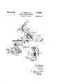
- One of the principal objects of this invention is to devise a steering column gearshift control adaptable for use on agricultural tractors and the like which will be adapted to the rigorous service required in such vehicles. Since most tractors are built around a tubular member which serves both as the frame and as the enclosurefor the transmission. propeller shaft, differentialand axle, the gearshift constructions which are adapted to passenger automobiles'or trucks having a conventional frame and chassis, are not entirely suitable. conventional three forward speeds used in passenger automobiles are insuflicient to obtain maximum performance from a tractor, the control must be adaptable to the operation of transmissions having at least four forward speeds as well as a reverse. Because of the space restriction imposed-by the relatively narrow tubular frame, the width of the control mechanism, including the scope of its necessary movement, must be held Still another object is that, since the Figure 1 is a longitudinal sectional elevation of a tractor employing the present invention.
- Figure 2 is a similar elevation on an enlarged scale showing, particularly, the association between the transmission and the steering column 1 of the transmission shift bars to the controlling mechanism.
- Figure 4 is an elevation of the distant side of the pedestal as shown in Figure 2.
- Another object of the invention is to provide a steering column gearshift to-not only withstand the extremely hard service met with on agricultural tractors but which, in addition, will be readily accessible and so constructed as to be readily re- With these and other objects in view, the invention consists in the arrangement, construction and'combination of the various parts of the improved device, as described in the specification, claimed in the claims, and illustrated in the accompanying drawings in which:
- Figure 5 is a transverse section taken as indicated by the line 5-5 on Figure 2.
- Figure 6 is a transverse section through the control rod taken as indicated by the line 6-6 on Figure 2.
- FIG. 1 indicates generally a tractor of the well-known Ford type having a motor I l and a relatively narrow tubular frame l2 extending rearwardly therefrom and enclosing the transmission shown generally at I3, the differential M, the main drive [5, the power take-off unit It and the hydraulic control i1.
- axles 32 mounting the wheels 33.
- the first and second gears 38 and 38 are integrallyformed on the hub 43, which is slidable on the splines 'of the driven shaft 23.
- the third speed is effected by engaging the hub 44, which is also slidable. I on the splines of driven shaft 23,
- a pump 46 is driven from the tube I8 through operating 'fluidlto the As is customary in this type cross shaft 56.
- the power-take-ofl. unit I6 comprises a trans? verse shaft 58 drivingly connected with a belt pulley which is operatedthrough the beveled gearing 54 and the clutch 55 by, the take-off drive shaft I8. It also comprises a longitudinal'takeoff shaft 56 which is driven through the gearing 51 and the clutch 55 by the take-off drive shaft I6. Suitable shields 58 and 58 are provided as more fully described in the above-noted copending applications.
- the steering shaft 64 is rotatablysupported therein.
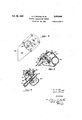
- the housing 63 also includes a substantially rectangular box section 65 shown in plan view at- Figure and in elevation at Figure 6 and having an opening 66 on the distant vertical side.
- An abutment 61 is secured adjacent the top of the column 62 mounting a pivot pin 68 servingas a fulcrum for the inner end of the gearshift lever 68 and as the upper guide for the gearshift control rod 16.
- This rod is fixedly secured to the sleeve 12 in which the lever 68 is rotatably mounted as by the ball joint 13 offset from the axis of rod 16.
- the rod 16 may be reciprocated upwardly or downwardly by similar movement of the lever 68 or rotated in response to rotation of the lever.
- This mechanism by means of which both rotary and vertical motion are imparted to of the rod 16 is slidably journaled in the recess 14 forming a downward extension of the box 65 and opposing springs 15 and 16 having a suitably varied rate and are provided to maintain the rod 16 and its associated lever 68 in a' median or neutral osition.
- the upper collar 11 is pinned is not visible, but it carries the reversing I g to the rod 16 within the box 65 and is integrally (formed with an arm- 86 extending through the opening 66 (as is best seen'in Figure 5), terminating in the finger 18 which is engaged in the 5 slot 81 of the modified H plate 18.
- An elongated hole 82 is formed in the arm 86 and receives the cranked end '83 of the link 84' which, therefore, transmits the rotational movements of the rod 16.
- a lower collar 85 is loosely mountedon the and pin 86 beneath. This lower collar is formed at the cranked end 81 of the link 88, which serves trol rod 16. It will thus be apparent that vertical movement of the lever 68 is reflected in relative rotation of the link 86 about the pivot fulcrum 88 which is mounted on the tractor frame I2; and that rotational movement of the lever 68, relative to the column 62, is reflected in longitudinal reciprocation of the link 84. 7
- Both links 84 and 68 are enclosed within a conduit 86 formed of two stampings of relatively light gage sheet metal extending obliquely from the box 65 to the tractor frame I2 and bolted about the opening 82 in the top thereof.
- the stamping 83 forming the near side of the conduit 86 in Figure 2 has an opening 8
- Thestamp- 3 ing 84 forming'thedistant side also has an opening H of somewhat smaller extent and over this ,is bolted the H plate 18 referred to above.
- the bolt holes 86 through which the H plate is attached to the stamping 84 permit some play to facilitate adjustment of the plate 18 and thereby to regulate the movement of the shifting mechanism as reflected in the path followed by the finger 18.
- a cover 86 is bolted over the H plate 18 as a further protection. It will be apparent that by removal of the cover 86 and the H plate 18, the entire lower portion of the steering column control is readily available for adjustment or.-re-' with its respective notches I63, I64 and I65, which are aligned transversely of the tractor when in neutral position as indicated in Figure 3.
- An operating lever I66 has a ball head I61 universallyeo mounted in thesocket I68 secured to the tractor frame i2; and a small ball I68 at its foot adapted to be engaged selectively in the notches I63, I64
- a pin I II6 traverses the ball head I61 and is engaged by 85 the fork end H2 (shown in dotted line in Figure 2 and in section in Figure '3) 'of the link 88.
- An intermediate extension II3 on-the lever I66 is pivotally connected with'the end of the link 84 at III. l
- a stamped cowl H5 which also serves as an instrument panel and as the upper support for the steering column and control rod. This extends forwardly at H8 as'the fuel tank and engine hood and downwardly at ill to en close the steering column.
- An opening H8 is provided around the housing 63, though this is covered in by the relatively narrow hood H9. The lateral compactness of the device may be judged from the thickness of the conduit required,
- a tractorframe a tractorframe, a steering column rigidly secured to said frame, a housing associated with said steering column, a gearshift rod extending along said column and being slidably and rotatably supv ported thereon, means at the upperend thereof to reciprocate and to rotate said rod, means noron, rotation of said rod, asecond extension rotatably mounted on said rod adjacent said first
- the device is extension, a fulcrum about which said second extension is rotatable on reciprocation of said rod
- a transmission operating lever suspended by a v joint for universal movement and. having its lower endselectively engaging one of a plurality of transmissionoperating forks, said second extension engaging said operating lever adjacent said joint to rotate said operating lever transversely into selective engagementwith said forks, said first extension engaging said operating lever at a point distant from said joint to move said operating lever longitudinally toactuate the fork so selected.
- a tractor transmission control a tractor frame, a steering column rigidly secured to said frame, a housing associated with said steering column, a gearshift rod extending along said col umn and being slidably and rotatably supported thereon, means at the upper end thereof to reciprocate and to rotate said rod, resilient means normally urging said rod to a median position corresponding to neutral position of the tractor transmission, an extension secured adjacent the lower, end of said rod to be reciprocated thereby on rotation of said rod, a second extension ro-' tatably mounted on said rod adjacent said first a finger formed on one of said extensions engaging the opening in said H plate to limit the operation of said extension.
- a tractor transmission control a tractor frame, a steering column rigidly secured to said frame, a housing associated with said steering column, a, gearshift rod extending along said column'and being slidably and rotatably supported thereon, means at the upper end thereof to reciprocate and to rotate said rod, resilient means normally urging said rod to a median position corresponding to neutral position of the tractor transmission, 'an extension secured adjacent the lower end of said rod to be reciprocated thereby on rotation-of said rod, a second extension rotatablyiiountedor said rod adjacent said first extension, a fulcrumabout which said second extensionis rotatable on reciprocation of said rod, atransmission operating lever suspended by a'ball joint for universal movement and having its lower end'selectively engaging one of a plurality of transmission operating forks, two of said forks controlling the forward speeds of said transmission and the third said fork controlling a reverse speed of said transmission, said second extension engaging said operating lever adjac'ent said ball joint to rotate said operating lever trans
- a tractor transmission control a tractor frame, a steering column rigidly secured to said extending along said column and being slidably and rotatably supported thereon; means at the upper end thereof to reciprocate and to rotate said rod, resilient means normally urging said rod to a median position correspondingto neutral 1 position of the tractor transmission, an extension. secured adjacent the lower end of said rod to be reciprocated thereby on rotation of said rod, a
- a tractor transmission control a tractor rframe, a steering column rigidly secured to said frame, a housing associated with said steering column above said frame, a gearshift rod extending along said column and being" slidably and rotatably supported thereon, means at the upper end thereof to reciprocate and to rotate said rod tween said housing andthe interior of said tractor frame, said conduit.
- said conduit including an H plate adjacent to said housing, a finger on one said extension engaging the slot in said H plate to rei strict the routine'of movement of said rod, a
- a tractor transmission control a substantially tubular tractor frame, a steering column rigidly secured to said frame, a housing asframe, said second link engaging said operating lever eccentrically laterally to impart transverse movement thereto, said first link engaging said operating lever eccentrically vertically to impart .longitudinal movement thereto, said operating leverengaging one of a plurality of transmission control forks mounted on vertically staggered transmission slide b'ars, said operating lever with said rod in its extreme position engaging the forks controlling the forward speeds of said transmission and when said rod is adjacent the median position engaging the fork controlling a, reverse speed of said transmission.
- a tractor transmission control a substantially tubular tractor frame, asteering column rigidlysecured to said frame, a housing associated with said steering column above said frame, a chamber in said housing closed with respect to said steering column, a gearshift rod extending along said column and being slidably and rotatably supported thereon and terminating within said chamber, means at the upper end of said'rod to reciprocate and to rotate said rod with respect to said steering-column, means within' said chamber normally maintaining said red at a median position corresponding to neutral position of the tractor transmission, a collar rigidly secured to said rod adjacent the lower end thereof and hav ing an extension projecting laterally from said chamber, a finger at the end of said extension, a conduitamxed to one side of said chamber and leading to the top of said tractor frame, an H plate forming a part.
Landscapes
- Engineering & Computer Science (AREA)
- General Engineering & Computer Science (AREA)
- Mechanical Engineering (AREA)
- Arrangement Or Mounting Of Control Devices For Change-Speed Gearing (AREA)
Description
b 4 c. P. PINARDI ETAL 3 1 moron Tmsussmgz comraor. I
Filed Jan. 18; 1945 ,s sheets-sna 2 Feb. 25, 1947. c. P. PINARDI 17m. 2,415,640
7 mcmoa numsuxsslqu connoi- Filed Jan. 13, 1945 s sheets-sheet 3 IN VEN TORD B (JAM D C? Q 6. I @y:
Patented Feb. 25, 11 947 uNiT-Eo STATE TRACTOR TRANSMISSION CONTROL Charles P,. Pinardi, Dear-born, and Harold Brock, Detroit, Mich., assignors to Ford Motor Company, Dearborn, Mich., a corporation of Delaware Application January is, 1945, Serial No. 513,452
Claims. (01. 14-484) This invention relates to a transmission and control for automotive vehicles; and, more particularly, to a steering column gearshift control adapted for transmissions having four or more forward speeds.
One of the principal objects of this invention is to devise a steering column gearshift control adaptable for use on agricultural tractors and the like which will be adapted to the rigorous service required in such vehicles. Since most tractors are built around a tubular member which serves both as the frame and as the enclosurefor the transmission. propeller shaft, differentialand axle, the gearshift constructions which are adapted to passenger automobiles'or trucks having a conventional frame and chassis, are not entirely suitable. conventional three forward speeds used in passenger automobiles are insuflicient to obtain maximum performance from a tractor, the control must be adaptable to the operation of transmissions having at least four forward speeds as well as a reverse. Because of the space restriction imposed-by the relatively narrow tubular frame, the width of the control mechanism, including the scope of its necessary movement, must be held Still another object is that, since the Figure 1 is a longitudinal sectional elevation of a tractor employing the present invention.
Figure 2 is a similar elevation on an enlarged scale showing, particularly, the association between the transmission and the steering column 1 of the transmission shift bars to the controlling mechanism.
Figure 4 is an elevation of the distant side of the pedestal as shown in Figure 2.
at a minimum throughout. Therefore, the conventional controls heretofore used which have laterally disposed bell cranks and similar apparatus are unavailablefor tractor use. Another object of the invention is to provide a steering column gearshift to-not only withstand the extremely hard service met with on agricultural tractors but which, in addition, will be readily accessible and so constructed as to be readily re- With these and other objects in view, the invention consists in the arrangement, construction and'combination of the various parts of the improved device, as described in the specification, claimed in the claims, and illustrated in the accompanying drawings in which:
Figure 5 is a transverse section taken as indicated by the line 5-5 on Figure 2.
Figure 6 is a transverse section through the control rod taken as indicated by the line 6-6 on Figure 2.
Referring first to Figure 1, It] indicates generally a tractor of the well-known Ford type having a motor I l and a relatively narrow tubular frame l2 extending rearwardly therefrom and enclosing the transmission shown generally at I3, the differential M, the main drive [5, the power take-off unit It and the hydraulic control i1.
Certain of the constructional details of this machine are described at length in the copending application forPqwer take-off drive unit, Serial Number 570,292, filed December 29, 1944, by H. L. Brook and C. P. Pinardi, and Power take-off drive for tractors, Serial Number 570,293, filed December 29, 1944, by H. L. Brock et a1. It is suflicient for the purposes of this application to note that two independent drives are operated from the engine ll, one of which is represented by the take-off drive shaft [8, which is splined at its forward end directly to the crankshaft of the engine I l and the other by the tube l9 which engages the engine ll through the medium of the conventional clutch 20. The driving shaft 22 of the transmission l3 drivingly engages the rear end of the tube I9 and is itself tubular in form to permit the independent rotation of the power main drive gears 30 secured to the independent.
axles 32 mounting the wheels 33.
The requisite torque conversion is obtained in the transmission by the integrally formed pinions i shaft 22 the gearing '41 to furnish u hydraulic control operating cylinder 48 (the piston not being shown) which in turn' operates, a
through the shaft. 48, the implement operating inggears indicated at 38, 38, 46 and 4|. The first and second gears 38 and 38 are integrallyformed on the hub 43, which is slidable on the splines 'of the driven shaft 23. The third speed is effected by engaging the hub 44, which is also slidable. I on the splines of driven shaft 23,
with the gear 46 which is keyed to the shaft 23. The fourth speed is obtained by moving the hub 44' rearinto engagement with the wardly to bring gear pinion 31. A third shaft lying behind the driveidler which is indicated in Figure 3 at 45 slidably mounted thereon and this may be engaged in the usual manner between the low-speedp-pinion and.
low-speed .gear. to effect reverseope'rationof the driven shaft 23.
A pump 46 is driven from the tube I8 through operating 'fluidlto the As is customary in this type cross shaft 56. V
hydraulic actuator of tractor, the operation of the is controlled by the spring resistance 52 which is 1 attached, through suitable linkage not shown, to the draft implement.
The power-take-ofl. unit I6 comprises a trans? verse shaft 58 drivingly connected with a belt pulley which is operatedthrough the beveled gearing 54 and the clutch 55 by, the take-off drive shaft I8. It also comprises a longitudinal'takeoff shaft 56 which is driven through the gearing 51 and the clutch 55 by the take-off drive shaft I6. Suitable shields 58 and 58 are provided as more fully described in the above-noted copending applications.
Reference is now made to the steering column assembly. This comprises a steering wheel 66 on the steering shaft 64 rotatably supported in the column 62 which terminates in an enlarged housing 63 at its lower end bolted to'the frame I2 and enclosing a steering gear .of the general type shown in United States Letters Patent 2,247,-
i 725. The steering shaft 64 is rotatablysupported therein. The housing 63 also includes a substantially rectangular box section 65 shown in plan view at- Figure and in elevation at Figure 6 and having an opening 66 on the distant vertical side. An abutment 61 is secured adjacent the top of the column 62 mounting a pivot pin 68 servingas a fulcrum for the inner end of the gearshift lever 68 and as the upper guide for the gearshift control rod 16. This rod is fixedly secured to the sleeve 12 in which the lever 68 is rotatably mounted as by the ball joint 13 offset from the axis of rod 16. Thus, the rod 16 may be reciprocated upwardly or downwardly by similar movement of the lever 68 or rotated in response to rotation of the lever. This mechanism by means of which both rotary and vertical motion are imparted to of the rod 16 is slidably journaled in the recess 14 forming a downward extension of the box 65 and opposing springs 15 and 16 having a suitably varied rate and are provided to maintain the rod 16 and its associated lever 68 in a' median or neutral osition. The upper collar 11 is pinned is not visible, but it carries the reversing I g to the rod 16 within the box 65 and is integrally (formed with an arm- 86 extending through the opening 66 (as is best seen'in Figure 5), terminating in the finger 18 which is engaged in the 5 slot 81 of the modified H plate 18. An elongated hole 82 is formed in the arm 86 and receives the cranked end '83 of the link 84' which, therefore, transmits the rotational movements of the rod 16. A lower collar 85 is loosely mountedon the and pin 86 beneath. This lower collar is formed at the cranked end 81 of the link 88, which serves trol rod 16. It will thus be apparent that vertical movement of the lever 68 is reflected in relative rotation of the link 86 about the pivot fulcrum 88 which is mounted on the tractor frame I2; and that rotational movement of the lever 68, relative to the column 62, is reflected in longitudinal reciprocation of the link 84. 7
Both links 84 and 68 are enclosed within a conduit 86 formed of two stampings of relatively light gage sheet metal extending obliquely from the box 65 to the tractor frame I2 and bolted about the opening 82 in the top thereof. The stamping 83 forming the near side of the conduit 86 in Figure 2 has an opening 8| corresponding to the opening 66 in the box section. Thestamp- 3 ing 84 forming'thedistant side also has an opening H of somewhat smaller extent and over this ,is bolted the H plate 18 referred to above. The bolt holes 86 through which the H plate is attached to the stamping 84 permit some play to facilitate adjustment of the plate 18 and thereby to regulate the movement of the shifting mechanism as reflected in the path followed by the finger 18. A cover 86 is bolted over the H plate 18 as a further protection. It will be apparent that by removal of the cover 86 and the H plate 18, the entire lower portion of the steering column control is readily available for adjustment or.-re-' with its respective notches I63, I64 and I65, which are aligned transversely of the tractor when in neutral position as indicated in Figure 3. An operating lever I66 has a ball head I61 universallyeo mounted in thesocket I68 secured to the tractor frame i2; and a small ball I68 at its foot adapted to be engaged selectively in the notches I63, I64
or I to operate the respective forks. A pin I II6 traverses the ball head I61 and is engaged by 85 the fork end H2 (shown in dotted line in Figure 2 and in section in Figure '3) 'of the link 88. An intermediate extension II3 on-the lever I66 is pivotally connected with'the end of the link 84 at III. l
The operation of the gear selector is believed to be quite clear. Starting at the neutral position shown, the operating lever I66 is in the intermediate or reverse notch- I63 and rotation of tend the link 84 pivoting the-operating lever I66 rod 16, although .its' vertical movement is re-' strictedby the upper collar 11, and the washer to translate the-vertical reciprocations of the conof Figure 2 in which the transmission control I6I operating the first the gearshift lever 68 in the proper sense will ex.-'
the link 84 pivoting the operating lever I08 and H moving the fork llll to effect the desired gear engagement. Corresponding routines are followed for each of the forward speeds. It will be recognized that suitable interlocking means must be operable between the various slide bars to prevent multiple operation of the forks and to restrict the shifting routine to that desired for normal operation. These may follow conventional practice as exemplified in the ordinary types of transmissions.
The construction is completed, as shown in Figure 1, by a stamped cowl H5, which also serves as an instrument panel and as the upper support for the steering column and control rod. This extends forwardly at H8 as'the fuel tank and engine hood and downwardly at ill to en close the steering column. An opening H8 is provided around the housing 63, though this is covered in by the relatively narrow hood H9. The lateral compactness of the device may be judged from the thickness of the conduit required,
as shown in Figure 5; and it will be apparent.
that the lateral amplitude of movement of the various parts is maintained at a minimum, as will be seen in Figure 3. particularly applicable for use on tractors where space is limited, as opposed to current automotive practice in which substantially the entire distance between the sills of the frame is available for installation and operation. ,Another advantage of the present embodiment is that the operating mechanism, while fully protected, is readily available and is not enclosed in the tubu- .1ar frame of the tractor, which is comparable to the construction used in automotive work. It will further be noted that only a, singlecontrol tube is required to obtain the five positions of active transmission engagement required in the present embodiment and that by increasing the amplitude of travel of the link and correspondingly in creasing the number of notches and forks, an even larger number of selectiveiposig tions may be obtained with the same basic apparatus. Thus the device is most valuable for use in heavy-duty equipment in which graduated torque control is essential.
Some changes may be made in the apparatus described, without departing from the spirit of the invention, and it is the intention to cover by the claims such changes as may reasonably'be included within .the scope thereof.
The invention claimed is:
1. In a tractor transmission control, a tractorframe, a steering column rigidly secured to said frame, a housing associated with said steering column, a gearshift rod extending along said column and being slidably and rotatably supv ported thereon, means at the upperend thereof to reciprocate and to rotate said rod, means noron, rotation of said rod, asecond extension rotatably mounted on said rod adjacent said first Thus, the device is extension, a fulcrum about which said second extension is rotatable on reciprocation of said rod,
a transmission operating lever. suspended by a v joint for universal movement and. having its lower endselectively engaging one of a plurality of transmissionoperating forks, said second extension engaging said operating lever adjacent said joint to rotate said operating lever transversely into selective engagementwith said forks, said first extension engaging said operating lever at a point distant from said joint to move said operating lever longitudinally toactuate the fork so selected.
2. In a tractor transmission control, a tractor frame, a steering column rigidly secured to said frame, a housing associated with said steering column, a gearshift rod extending along said col umn and being slidably and rotatably supported thereon, means at the upper end thereof to reciprocate and to rotate said rod, resilient means normally urging said rod to a median position corresponding to neutral position of the tractor transmission, an extension secured adjacent the lower, end of said rod to be reciprocated thereby on rotation of said rod, a second extension ro-' tatably mounted on said rod adjacent said first a finger formed on one of said extensions engaging the opening in said H plate to limit the operation of said extension.
3. In a tractor transmission control, a tractor frame, a steering column rigidly secured to said frame, a housing associated with said steering column, a, gearshift rod extending along said column'and being slidably and rotatably supported thereon, means at the upper end thereof to reciprocate and to rotate said rod, resilient means normally urging said rod to a median position corresponding to neutral position of the tractor transmission, 'an extension secured adjacent the lower end of said rod to be reciprocated thereby on rotation-of said rod, a second extension rotatablyiiountedor said rod adjacent said first extension, a fulcrumabout which said second extensionis rotatable on reciprocation of said rod, atransmission operating lever suspended by a'ball joint for universal movement and having its lower end'selectively engaging one of a plurality of transmission operating forks, two of said forks controlling the forward speeds of said transmission and the third said fork controlling a reverse speed of said transmission, said second extension engaging said operating lever adjac'ent said ball joint to rotate said operating lever transversely into selective engagement with said forks, said first extension engaging said operating lever at a point distant from said ball joint to rotate said operating lever longitudinally to actuate the fork so selected, and regulating means adjacent the lower portion of said rod to restrict the operation thereof to desired successive positions of engagement.
4. In a tractor transmission control, a tractor frame, a steering column rigidly secured to said extending along said column and being slidably and rotatably supported thereon; means at the upper end thereof to reciprocate and to rotate said rod, resilient means normally urging said rod to a median position correspondingto neutral 1 position of the tractor transmission, an extension. secured adjacent the lower end of said rod to be reciprocated thereby on rotation of said rod, a
second'extension rotatably mounted on said rod adjacent said first extension, a fulcrum about which said second extension is rotatable on re-.' ciprocation of said rod, a transmission operating lever suspended by a ball joint for universal movement and having its lower end selectively engagengaging saidpin eccentrically with respect to saidballfijoint' to rotate said operating lever. l transversely into selective engagement with said lframe, a. housing associated with said steering column spaced above said frame, a gearshift rod sociated with said steering column above said tractor frame, a gearshift rod extendingalong' said column and being slidably and rotatably supported thereon with respect thereto, means at the upper end thereof to reciprocate and to rotate said rod, resilient means within said hous- I ing normally urging said rod to a median position corresponding to neutral position of the tractor transmission, a' collar rigidly secured to saidrod adjacent at the bottom thereof and extending from said housing, a second collar rotatably sup- 1 ing one of a plurality of transmission operating forks, a pin extending transversely from said ball joint, said second extension terminating in a fork ported on said rod" adapted to be reciprocated therewith, a conduit associated with said housing and extending therefrom to said tractor frame, a link within said conduit engaging said extension, a second linkwithin said conduit rigidly connected with said second collar, a fulcrum on said tractor frame for said second link whereby reciprocation of said r'od provides limited. rotation of said link, both of said links being in substantiallythe same vertical plane, a transmission operating lever suspended from said tractor forks, saidfirst extension engaging said operat--[ 'ing lever at a point distant from said ball joint to rotate said operating lever longitudinally to actuate the fork soselected, two of said forks perating the-forward speed gears of said transmission and. a third fork operating a reverse j.speed gear of said transmission.
' 5. In a tractor transmission control, a tractor rframe, a steering column rigidly secured to said frame, a housing associated with said steering column above said frame, a gearshift rod extending along said column and being" slidably and rotatably supported thereon, means at the upper end thereof to reciprocate and to rotate said rod tween said housing andthe interior of said tractor frame, said conduit. including an H plate adjacent to said housing, a finger on one said extension engaging the slot in said H plate to rei strict the routine'of movement of said rod, a
fulcrum on said tractor frame about which said said rod, 3, transmission-operating lever suspended from a connection on said frame permitting universal movement thereof and having its lower j end selectively. engaging one of a plurality of 1 transmission operating forks, said second extenf sion engaging said operating lever eccentrically lever transversely into selective engagement with said forks, said first extension engaging said opperating lever at a point distant from'said joint to rotate said operating lever longitudinally vto actuate the fork so selected, the forks of said transmission engaged by said operating lever at a the extreme positions of said rod controlling the second extension is rotatable on reciprocation 'of i adjacent said connection to rotate said operating forward speeds of said transmission and thefork engaged by said'operating lever when adjacent th median position controlling a reverse speed of said transmission.
6. In a tractor transmission control, a substantially tubular tractor frame, a steering column rigidly secured to said frame, a housing asframe, said second link engaging said operating lever eccentrically laterally to impart transverse movement thereto, said first link engaging said operating lever eccentrically vertically to impart .longitudinal movement thereto, said operating leverengaging one of a plurality of transmission control forks mounted on vertically staggered transmission slide b'ars, said operating lever with said rod in its extreme position engaging the forks controlling the forward speeds of said transmission and when said rod is adjacent the median position engaging the fork controlling a, reverse speed of said transmission.
7. In a tractor transmission control, a substantially tubular tractor frame, asteering column rigidlysecured to said frame, a housing associated with said steering column above said frame, a chamber in said housing closed with respect to said steering column, a gearshift rod extending along said column and being slidably and rotatably supported thereon and terminating within said chamber, means at the upper end of said'rod to reciprocate and to rotate said rod with respect to said steering-column, means within' said chamber normally maintaining said red at a median position corresponding to neutral position of the tractor transmission, a collar rigidly secured to said rod adjacent the lower end thereof and hav ing an extension projecting laterally from said chamber, a finger at the end of said extension, a conduitamxed to one side of said chamber and leading to the top of said tractor frame, an H plate forming a part. of said conduit and adapted to engage the finger on said extension, a slot formedin said extension, a link engaged in said slot and leading to said conduit through the interior of said tractor frame, a second collar rotatably supported on said red. but secured for reciprocation therewith having a link formed integrally. therewith and extending from said chamber. through said conduit to the interior of said tractor frame, a tractor transmission within said frame, a transmission operating lever univers'ally suspended from said tractor frame, said V first link engaging said operating lever eccentrically' vertically of said universal joint to impart longitudinal movement to the lower end of said operatinglever, said second link engaging said operating lever eccentrically' laterallyof said uni-. p versal joint to impart transverse movementto said operating lever on reciprocation of said rod,
a plurality'of vertically staggered slide bars in said transmission, transmission operating forks
Priority Applications (2)
| Application Number | Priority Date | Filing Date | Title |
|---|---|---|---|
| US573452A US2416640A (en) | 1945-01-18 | 1945-01-18 | Tractor transmission control |
| ES175964A ES175964A1 (en) | 1945-01-18 | 1946-11-30 | IMPROVEMENTS IN THE TRACTOR TRANSMISSION COMMAND |
Applications Claiming Priority (1)
| Application Number | Priority Date | Filing Date | Title |
|---|---|---|---|
| US573452A US2416640A (en) | 1945-01-18 | 1945-01-18 | Tractor transmission control |
Publications (1)
| Publication Number | Publication Date |
|---|---|
| US2416640A true US2416640A (en) | 1947-02-25 |
Family
ID=24292049
Family Applications (1)
| Application Number | Title | Priority Date | Filing Date |
|---|---|---|---|
| US573452A Expired - Lifetime US2416640A (en) | 1945-01-18 | 1945-01-18 | Tractor transmission control |
Country Status (2)
| Country | Link |
|---|---|
| US (1) | US2416640A (en) |
| ES (1) | ES175964A1 (en) |
Cited By (4)
| Publication number | Priority date | Publication date | Assignee | Title |
|---|---|---|---|---|
| US2615346A (en) * | 1945-10-29 | 1952-10-28 | Borg Warner | Transmission |
| US2888998A (en) * | 1952-05-16 | 1959-06-02 | Massey Harris Ferguson Ltd | Tractor with power take-off for auxiliary pump |
| US4560021A (en) * | 1981-09-09 | 1985-12-24 | Fuji Jukogyo Kabushiki Kaisha | Control system for a plurality of engine units |
| FR2608529A1 (en) * | 1986-12-22 | 1988-06-24 | Kubota Ltd | CHASSIS TYPE TRACTOR WITH ENGINE AND CLUTCH SEPARATED BY IMPORTANT SPACING |
-
1945
- 1945-01-18 US US573452A patent/US2416640A/en not_active Expired - Lifetime
-
1946
- 1946-11-30 ES ES175964A patent/ES175964A1/en not_active Expired
Non-Patent Citations (1)
| Title |
|---|
| None * |
Cited By (5)
| Publication number | Priority date | Publication date | Assignee | Title |
|---|---|---|---|---|
| US2615346A (en) * | 1945-10-29 | 1952-10-28 | Borg Warner | Transmission |
| US2888998A (en) * | 1952-05-16 | 1959-06-02 | Massey Harris Ferguson Ltd | Tractor with power take-off for auxiliary pump |
| US4560021A (en) * | 1981-09-09 | 1985-12-24 | Fuji Jukogyo Kabushiki Kaisha | Control system for a plurality of engine units |
| FR2608529A1 (en) * | 1986-12-22 | 1988-06-24 | Kubota Ltd | CHASSIS TYPE TRACTOR WITH ENGINE AND CLUTCH SEPARATED BY IMPORTANT SPACING |
| US4804056A (en) * | 1986-12-22 | 1989-02-14 | Kubota Limited | Frame type tractor |
Also Published As
| Publication number | Publication date |
|---|---|
| ES175964A1 (en) | 1947-03-01 |
Similar Documents
| Publication | Publication Date | Title |
|---|---|---|
| US2445716A (en) | Dual transmission control | |
| US9309967B2 (en) | Gearshift mechanism and working vehicle | |
| US4723622A (en) | Wheel drive mode changeover apparatus | |
| US3600966A (en) | Compound motion transmitting cable mechanism | |
| US2416640A (en) | Tractor transmission control | |
| US1533531A (en) | Auxiliary transmission | |
| US2357781A (en) | Transmission control mechanism | |
| US2252158A (en) | Gear shifting mechanism | |
| GB2098678A (en) | Vehicle transmission | |
| US2094976A (en) | Motor vehicle construction | |
| US2299889A (en) | Remote shift mechanism | |
| US2324732A (en) | Power transmission | |
| US3282123A (en) | Control console for motor grader | |
| US2377700A (en) | Control mechanism | |
| US2202949A (en) | Gearshift mechanism | |
| US2249176A (en) | Remote control gearshift | |
| GB1182766A (en) | Remote Control of Gearbox Mechanism | |
| US2584058A (en) | Control mechanism for change-speed gearing on motor vehicles | |
| US2284191A (en) | Variable speed transmission mechanism | |
| USRE15614E (en) | Variable-speed device | |
| JPH05246258A (en) | Pto speed change control device for tractor | |
| US2346332A (en) | Speed regulating mechanism | |
| US1888644A (en) | Automotive vehicle | |
| US2391783A (en) | Transmission | |
| JPS5843624B2 (en) | Mission structure of 4-wheel drive agricultural tractor |