US241069A - Mes eigby - Google Patents
Mes eigby Download PDFInfo
- Publication number
- US241069A US241069A US241069DA US241069A US 241069 A US241069 A US 241069A US 241069D A US241069D A US 241069DA US 241069 A US241069 A US 241069A
- Authority
- US
- United States
- Prior art keywords
- tire
- eigby
- mes
- recesses
- studs
- Prior art date
- Legal status (The legal status is an assumption and is not a legal conclusion. Google has not performed a legal analysis and makes no representation as to the accuracy of the status listed.)
- Expired - Lifetime
Links
- 238000010276 construction Methods 0.000 description 4
- 229910000831 Steel Inorganic materials 0.000 description 2
- 239000010959 steel Substances 0.000 description 2
- 239000000463 material Substances 0.000 description 1
- 239000002184 metal Substances 0.000 description 1
- 230000002093 peripheral effect Effects 0.000 description 1
- 108010085990 projectin Proteins 0.000 description 1
Images
Classifications
-
- B—PERFORMING OPERATIONS; TRANSPORTING
- B60—VEHICLES IN GENERAL
- B60B—VEHICLE WHEELS; CASTORS; AXLES FOR WHEELS OR CASTORS; INCREASING WHEEL ADHESION
- B60B17/00—Wheels characterised by rail-engaging elements
- B60B17/0055—Wheels characterised by rail-engaging elements with non-elastic tyres (e.g. of particular profile or composition)
Definitions
- WITNESSES INVENTDR'. dAMEEi RIGBY, (Vie. i BYa'flwfomanm ATTYE N. PETERS, Phcto Lithognphen Washington, 0. c
- This invention relates to that class of metal wheels which are provided with removable tires and flanges; and it consists, mainly, in certain special features of construction, fully described hereinafter, by means of which great strength is obtained with a low cost of production.
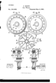
- Figure i represents an elevation of the outer side of my improved wheel 5 Fig. 2, an elevation of the inner side Fig. 3, an elevation taken from the inner side, with the plate a cut away to show the interior; and Figs. 4 and 5, vertical sectional elevations.
- A represents the body portion of the wheel, consisting of a hub portion, a, having an inner plate, a, an outer plate, a and intermediate radial arms, a terminating in a peripheral ring portion, a", as shown. These parts are cast together in one piece.
- a a represent enlargements formed at the point of the union of the arms a with the ring portion a, and a a openings through them for the securing-bolts, hereinafter referred to.
- a represents semi -cylindrieal recesses located at proper points about the periphery of the wheel, the purpose of which will be fully described hereinafter.
- B represents the tire portion, consisting of a steel ring having one inclined side, b, and the semi-cylindrical recesses b, Fig. 3, corresponding in location with the similar recesses in the body portion, as shown.
- J, Figs. 1, 2, 4, and 5 represents the flange portion, consisting of a steel ring having an inner portion, 0, with parallel sides, a series of openings, 0, Fig. 4, and studs or pins 0 Fig. 5, the latter corresponding in size and location with the semicylindrical recesses in the body portion and the tire.
- the studs are screwed into the flange portion after the same has been finished in the lathe.
- 0 Fig. 4 represents an outer portion of the ring, having an inclined face, 0", corresponding properly with the inclined face of the tire, and a flange portion proper, 0 having upon one side the curved face 0 and upon the other the straight face 0 as shown.
- the tire portion rests upon the ring a of the body portion, with its straight side bearing against the projectin g portion of the outer plate, (R, as shown.
- the semi cylindrical recesses coincide with each other, so that a proper opening is formed for the studs 0 upon the flange portion.
- the flange portion rests upon the periphery of the inner plate, a, and against the body portion, as shown, its inclined face coinciding with the inclined face of the tire. Its studs 0 rest in the recesses of the body and tire, and thus securely hold the tire against movement upon the body portion.
Landscapes
- Engineering & Computer Science (AREA)
- Mechanical Engineering (AREA)
- Tires In General (AREA)
Description
(No Model.)
J. RIGBY.
Oar Wheel. No. 241,069. Patented May 3,1881.
WITNESSES: INVENTDR'. dAMEEi RIGBY, (Vie. i BYa'flwfomanm ATTYE N. PETERS, Phcto Lithognphen Washington, 0. c
llNrTnn STATES PATENT OFFICE JAMES RIGBY, OF MONTREAL, QUEBEC, CANADA.
CAR-WHEEL.
SPECIFICATION forming part of Letters Patent No. 241,069, dated May 3, 1881.
Application filed October 27, 1880.
To all whom 2t may concern Be it known that I, JAMES RIGBY, a citizen of the United States, residing at Montreal, in the Province of Quebec, Canada, have invented a new and useful Improvement in Oar-\Vheels; and I do hereby declare the following to be a full, clear, and exact description of the same, reference being had to the accompanying drawings, and to the letters of reference marked thereon.
This invention relates to that class of metal wheels which are provided with removable tires and flanges; and it consists, mainly, in certain special features of construction, fully described hereinafter, by means of which great strength is obtained with a low cost of production.
In the drawings, Figure i represents an elevation of the outer side of my improved wheel 5 Fig. 2, an elevation of the inner side Fig. 3, an elevation taken from the inner side, with the plate a cut away to show the interior; and Figs. 4 and 5, vertical sectional elevations.
To enable others skilled in the art to make my improved wheel, I will proceed to describe fully the construction of the same.
A, Figs. 1, 2, 3, 4, and 5, represents the body portion of the wheel, consisting of a hub portion, a, having an inner plate, a, an outer plate, a and intermediate radial arms, a terminating in a peripheral ring portion, a", as shown. These parts are cast together in one piece.
a a represent enlargements formed at the point of the union of the arms a with the ring portion a, and a a openings through them for the securing-bolts, hereinafter referred to.
a tflrepresent short arms, by means of which thering portion is united to the inner and outer plate portions at points between the radial arms a as shown.
a represents semi -cylindrieal recesses located at proper points about the periphery of the wheel, the purpose of which will be fully described hereinafter.
B, Figs. 1, 8, 4, and 5, represents the tire portion, consisting of a steel ring having one inclined side, b, and the semi-cylindrical recesses b, Fig. 3, corresponding in location with the similar recesses in the body portion, as shown.
(No model.)
(J, Figs. 1, 2, 4, and 5, represents the flange portion, consisting of a steel ring having an inner portion, 0, with parallel sides, a series of openings, 0, Fig. 4, and studs or pins 0 Fig. 5, the latter corresponding in size and location with the semicylindrical recesses in the body portion and the tire. The studs are screwed into the flange portion after the same has been finished in the lathe.
0 Fig. 4, represents an outer portion of the ring, having an inclined face, 0", corresponding properly with the inclined face of the tire, and a flange portion proper, 0 having upon one side the curved face 0 and upon the other the straight face 0 as shown. When the plates are properly united together the tire portion rests upon the ring a of the body portion, with its straight side bearing against the projectin g portion of the outer plate, (R, as shown. The semi cylindrical recesses coincide with each other, so that a proper opening is formed for the studs 0 upon the flange portion. The flange portion rests upon the periphery of the inner plate, a, and against the body portion, as shown, its inclined face coinciding with the inclined face of the tire. Its studs 0 rest in the recesses of the body and tire, and thus securely hold the tire against movement upon the body portion.
D D, Figs. 1, 2, 4, and 5, represent bolts, by means of which all the parts are firmly bound together.
Some of the advantages of this special construction are as folows: By extending the outer plate, a far enouglfoutward to hold the tire against lateral moyement, the construction is simplified and the iost is reduced. By the em ploymentof the short arms a great strength and rigidity is obtained with a small amount of material. By the employment of the studs 0 and the corresponding recesses the necessary connection between the parts is obtained. The flange portion 0 before the studs are inserted, may be readily finished in the lathe.
Having thus fully described my invention, what I claim as new, and desire to secure by Letters Patent, is
1. In combination with the body portion having the inner plate extending outward to hold the tire, the removable tire portion and flange I This specification signed and witnessed this portion, as described. 27th day of October, 1880.
2. The body portion having the inner and outer plates, the radial arms a, and the short JAMES RIGBY' arms a as described. Witnesses:
3. In combination with the body portion and H. W. BEADLE, tire having recesses, as described, the flange M. M. ROHRER.
portion having the studs, as described.
Publications (1)
| Publication Number | Publication Date |
|---|---|
| US241069A true US241069A (en) | 1881-05-03 |
Family
ID=2310408
Family Applications (1)
| Application Number | Title | Priority Date | Filing Date |
|---|---|---|---|
| US241069D Expired - Lifetime US241069A (en) | Mes eigby |
Country Status (1)
| Country | Link |
|---|---|
| US (1) | US241069A (en) |
-
0
- US US241069D patent/US241069A/en not_active Expired - Lifetime
Similar Documents
| Publication | Publication Date | Title |
|---|---|---|
| US241069A (en) | Mes eigby | |
| US429407A (en) | Henry w | |
| US499514A (en) | James buchanan | |
| US233701A (en) | Peters | |
| US180163A (en) | Improvement in felly-plates | |
| US411354A (en) | Car-wheel | |
| US37269A (en) | Improvement in anti-friction car-wheels | |
| US496633A (en) | Metal wheel and method of making same | |
| US1211572A (en) | Wheel for automobiles and the like. | |
| US402564A (en) | Sectional fly-wheel | |
| US1049378A (en) | Vehicle wheel-rim. | |
| US417995A (en) | Wheel | |
| US268378A (en) | Car-wheel | |
| US491456A (en) | Car-wheel | |
| US291618A (en) | Geoege w | |
| USD34108S (en) | Design for a car-wheel | |
| US740976A (en) | Car axle and wheel. | |
| US311434A (en) | Car-wheel | |
| US459976A (en) | Car-wheel | |
| US218453A (en) | Improvement in car-wheels | |
| US534353A (en) | Able ikon | |
| US515406A (en) | Wheel for door-hangers | |
| US405847A (en) | Edgar peckham | |
| US369752A (en) | Car-wheel | |
| US145783A (en) | Improvement |