US240328A - Haeeison ogbobf - Google Patents
Haeeison ogbobf Download PDFInfo
- Publication number
- US240328A US240328A US240328DA US240328A US 240328 A US240328 A US 240328A US 240328D A US240328D A US 240328DA US 240328 A US240328 A US 240328A
- Authority
- US
- United States
- Prior art keywords
- saddle
- caster
- stem
- wheel
- ogbobf
- Prior art date
- Legal status (The legal status is an assumption and is not a legal conclusion. Google has not performed a legal analysis and makes no representation as to the accuracy of the status listed.)
- Expired - Lifetime
Links
Images

Classifications
-
- B—PERFORMING OPERATIONS; TRANSPORTING
- B60—VEHICLES IN GENERAL
- B60B—VEHICLE WHEELS; CASTORS; AXLES FOR WHEELS OR CASTORS; INCREASING WHEEL ADHESION
- B60B33/00—Castors in general; Anti-clogging castors
- B60B33/0036—Castors in general; Anti-clogging castors characterised by type of wheels
- B60B33/0042—Double or twin wheels
Definitions
- the objects of the invention are to secure a caster that may be readily attached without taking it apart, to secure an equal pressure on each of the door-wheels, great mobility, freedom from friction, pivotal wear of the caster, and prevention of wear and tear of carpets and iloors; and to this end the invention consists in novelfeatures of construction to be hereinafter referred to, and specifically pointed out in the claims.
- Figure l is a rear elevation of my improved caster.
- Fig. 2 is a side elevation.
- Fig. 3 is a vertical section taken in the plane of the line y y, Fig. 5.
- Fig. 4 is a vertical section taken in the plane of the line w, Fig. 5.
- Fig. 5 is an inverted bottom view.
- Fig. 6 is a section similar to Fig. 4, showing a modification of my improvement, to be hereinafter referred to.
- K K are holes in saddle B, on a line with screw-holes P in plate D, through which screws are driven to attach the caster. If desired, nails may be substituted for screws and driven in.
- the saddle D is a plate, from which depends the central stem, F.
- This stem serves as a pivot for the swiveling motion, as a means ot' uniting ⁇ the parts, and as a draft-pin for saddle B and wheels A A and C.
- the saddle B is provided with a projection, E, which usually does not quite touch the plate D. This projection is placed ou the opposite side of the caster from the wheel C, and serves to prevent the too great deflection of the rear of the caster when it is lifted 0E the iioor.
- the saddle B furnishes bearing supports for the two floorwheels A A and wheel (l, as shown in Fig. 4. The latter wheel is situated centrally between and vertically above the door-wheels.
- saddle B has a compound motion with reference to the central pivot. It revolves upon a vertical axis and oscillates upon a horizontal axis.
- This compound bearing is formed by thickening the central part of saddle B, and making a hole, H, through it elliptical toward its sides on its upper and lower surfaces, as shown at U V, Figs. 3 and 5, and round in the center or middle of saddle B, and vertical at the front and rear sides of the hole, as shown in Fig. 4.
- the stem F has a circular horizontal groove, I, in it to receive the points N O.
- the screw M also acts as a journal for wheel C.
- the caster is held together by the set-screws L M and their points N O, and taken apart by Withdrawing them.
- Points N O fit loosely in the groove I, and allow the stem F to oscillate freely until it rests on the inclined part V of the hole H at the top and the inclined part of the hole U at the opposite under side.
- the saddle B will strike the plate at the same time.
- the points N O act as the pivotal center of motion.
- the hole H being vertical on the lfront and rear sides thereof, (sec Fig. 4,) prevents the caster dropping out of place when raised oli" the door.
- I may use a stem, G, without a groove, as clearly represented in Fig. 6, and secure it in place byacap, S, and screw T, and a friction-Wheel, Q, on stem R, which will prevent friction of the parts, and prevent the saddle falling too low on the stem Gr by said friction-wheel abuting against or engaging the inner face of the cap S.
Description
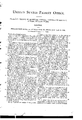
(man H. OGBORN.
' Caster.
No. 240,328. Patented April 19,1881.
@22268888 Zzwfeniaf- @mf M 48W @ff/M N.FETERS. PMOTUUTHOGRAPN n, WASHINGTON. cA
UNITED STATES- PATENT OFFICE.
HARRISON OGBORN, OF RICHMOND, INDIANA, ASSIGNOR TO RHODA C. OGBORN, OF SAME PLACE.
4CASTER.
SPECIFICATION forming part of Letters Patent No. 240,328, dated April 19, 1881.
` Application inea rebrumym, 1881. (Model.)
Io all whom it may concern:
Be it kno'wn that I, HARRISON OGBoRN, of'
Richmond, Wayne county, Indiana, have invented certain new and useful Improvements in Casters, of which the following is a specitlcation.
The objects of the invention are to secure a caster that may be readily attached without taking it apart, to secure an equal pressure on each of the door-wheels, great mobility, freedom from friction, pivotal wear of the caster, and prevention of wear and tear of carpets and iloors; and to this end the invention consists in novelfeatures of construction to be hereinafter referred to, and specifically pointed out in the claims. I
In the accompanying drawings, Figure l is a rear elevation of my improved caster. Fig. 2 is a side elevation. Fig. 3 is a vertical section taken in the plane of the line y y, Fig. 5. Fig. 4 is a vertical section taken in the plane of the line w, Fig. 5. Fig. 5 is an inverted bottom view. Fig. 6 is a section similar to Fig. 4, showing a modification of my improvement, to be hereinafter referred to.
Referring to the drawings, K K are holes in saddle B, on a line with screw-holes P in plate D, through which screws are driven to attach the caster. If desired, nails may be substituted for screws and driven in.
D is a plate, from which depends the central stem, F. This stem serves as a pivot for the swiveling motion, as a means ot' uniting` the parts, and as a draft-pin for saddle B and wheels A A and C. The saddle B is provided with a projection, E, which usually does not quite touch the plate D. This projection is placed ou the opposite side of the caster from the wheel C, and serves to prevent the too great deflection of the rear of the caster when it is lifted 0E the iioor. The saddle B furnishes bearing supports for the two floorwheels A A and wheel (l, as shown in Fig. 4. The latter wheel is situated centrally between and vertically above the door-wheels. The
saddle B swivels uponv the stein F, the pivot.
or center of motion being where the pins N O enter the groove I.
In my improvement saddle B has a compound motion with reference to the central pivot. It revolves upon a vertical axis and oscillates upon a horizontal axis. This compound bearing is formed by thickening the central part of saddle B, and making a hole, H, through it elliptical toward its sides on its upper and lower surfaces, as shown at U V, Figs. 3 and 5, and round in the center or middle of saddle B, and vertical at the front and rear sides of the hole, as shown in Fig. 4.
The stem F has a circular horizontal groove, I, in it to receive the points N O. The screw M also acts as a journal for wheel C. The caster is held together by the set-screws L M and their points N O, and taken apart by Withdrawing them. Points N O fit loosely in the groove I, and allow the stem F to oscillate freely until it rests on the inclined part V of the hole H at the top and the inclined part of the hole U at the opposite under side. The saddle B will strike the plate at the same time. The points N O act as the pivotal center of motion. The hole H being vertical on the lfront and rear sides thereof, (sec Fig. 4,) prevents the caster dropping out of place when raised oli" the door.
By means of the holes K in saddle B an easy mode of attaching the caster is provided; and by means of the relief resulting from making the hole H in the saddle elliptical at its upper and lower surface, vertical at its front and rear sides, and round at the center of the plate, (vertically,) with the points N O in groove I, great freedom of oscillation and pivotal rotation is secured without interfering with the central pivot as a draft-pin and means of union.
Instead of using the grooved stem F, I may use a stem, G, without a groove, as clearly represented in Fig. 6, and secure it in place byacap, S, and screw T, and a friction-Wheel, Q, on stem R, which will prevent friction of the parts, and prevent the saddle falling too low on the stem Gr by said friction-wheel abuting against or engaging the inner face of the cap S.
I am aware that it is not new to make a caster with two floor-wheels on the same axis journaled in a saddle bearing an anti-friction Wheel and swiveled to the furniture-plate. I therefore make no claim to this subject-matter, broadly.
What I claim as my invention isl. In a caster, the combination, with the grooved stem F, of the saddle B, having arecess for the reception of the wheel C, and openings for the reception of the securing screws, rivets, or pins L and M, the latter forming the 1o journal for said Wheel C, substantially in the manner herein shown and described.
2. In a caster, the combination, with the plate D and stem, of the saddle B, provided
Publications (1)
| Publication Number | Publication Date |
|---|---|
| US240328A true US240328A (en) | 1881-04-19 |
Family
ID=2309667
Family Applications (1)
| Application Number | Title | Priority Date | Filing Date |
|---|---|---|---|
| US240328D Expired - Lifetime US240328A (en) | Haeeison ogbobf |
Country Status (1)
| Country | Link |
|---|---|
| US (1) | US240328A (en) |
-
0
- US US240328D patent/US240328A/en not_active Expired - Lifetime
Similar Documents
| Publication | Publication Date | Title |
|---|---|---|
| US240328A (en) | Haeeison ogbobf | |
| US215993A (en) | Improvement in sheaves for rolling doors | |
| US123147A (en) | Improvement in casters for furniture | |
| US433721A (en) | Sliding-door hanger | |
| US344988A (en) | Caster | |
| US309273A (en) | Furniture-caster | |
| US457365A (en) | Philip g | |
| US190152A (en) | Improvement in furniture-casters | |
| US223702A (en) | Bxjsh | |
| US440875A (en) | Caster | |
| US555175A (en) | Ball-caster | |
| US277954A (en) | Charles stengel | |
| US314847A (en) | Feedeeick w | |
| US616820A (en) | Thill-coupling | |
| US134223A (en) | Improvement in casters for furniture | |
| US126143A (en) | Improvement in millstone-drivers | |
| US170454A (en) | Improvement in millstone-drivers | |
| US391053A (en) | William kopisch | |
| US141391A (en) | Improvement in stools | |
| US434651A (en) | William barry | |
| US150132A (en) | Improvement in casters | |
| US135286A (en) | Improvement in furniture-casters | |
| US498297A (en) | Furniture-caster | |
| US652128A (en) | Caster. | |
| US365809A (en) | Fotjeths to s |