US2401094A - Time delay apparatus - Google Patents
Time delay apparatus Download PDFInfo
- Publication number
- US2401094A US2401094A US541743A US54174344A US2401094A US 2401094 A US2401094 A US 2401094A US 541743 A US541743 A US 541743A US 54174344 A US54174344 A US 54174344A US 2401094 A US2401094 A US 2401094A
- Authority
- US
- United States
- Prior art keywords
- coil
- rod
- point
- receiving coil
- elongated member
- Prior art date
- Legal status (The legal status is an assumption and is not a legal conclusion. Google has not performed a legal analysis and makes no representation as to the accuracy of the status listed.)
- Expired - Lifetime
Links
- 239000000463 material Substances 0.000 description 14
- 238000001514 detection method Methods 0.000 description 3
- 235000013871 bee wax Nutrition 0.000 description 2
- 239000012166 beeswax Substances 0.000 description 2
- 230000005540 biological transmission Effects 0.000 description 2
- 238000006243 chemical reaction Methods 0.000 description 2
- 238000013016 damping Methods 0.000 description 2
- 230000001934 delay Effects 0.000 description 2
- 238000000034 method Methods 0.000 description 2
- 241000984642 Cura Species 0.000 description 1
- 101100289061 Drosophila melanogaster lili gene Proteins 0.000 description 1
- 230000000977 initiatory effect Effects 0.000 description 1
- 238000005259 measurement Methods 0.000 description 1
- 238000012986 modification Methods 0.000 description 1
- 230000004048 modification Effects 0.000 description 1
- 238000004904 shortening Methods 0.000 description 1
Images
Classifications
-
- H—ELECTRICITY
- H03—ELECTRONIC CIRCUITRY
- H03H—IMPEDANCE NETWORKS, e.g. RESONANT CIRCUITS; RESONATORS
- H03H9/00—Networks comprising electromechanical or electro-acoustic elements; Electromechanical resonators
- H03H9/30—Time-delay networks
- H03H9/38—Time-delay networks with adjustable delay time
Definitions
- This invention relates to time delay apparatus, and more particularly to apparatus for obtaining variable and controllable time delays of extremely short duration', of the order-of 10 to 1,000 microseconds.
- i0 indicates a rod or wire ci any suitable rod or wire it may be supported in any suitable manner, but preferably are provided with dampl y ing material so that sound waves reaching the The ends of the gli may be obtained when the ends of the rod or wire are imbedded in blocks oi beeswax, as indicated at il and i2.
- a permanent magnet i3 is diagrammatically indicated, to keep the rod or wire magnetiquel suilciently to retain good magneto-striction conversion.
- the coil i5 may be supplied with direct current pulses from a pulse generator i9 of any suitable type. Aswill be-understood, when a direct current is passed through the coil i5, there occurs ⁇ a momentary lengthening or shortening of the rod or wire ld, depending on the direction of current flow. This momentary distortion in the length oi the rod or wire l@ at the-point of coil i5 then travels down the rod in opposite directions as a sound wave, and its speed oi travelv is equal to the velocity of sound in the particular material at the particular temperature.
- the waves reaching the block of beeswax ii are absorbed or damped out to such a degreeA that no troublesome reiiection occurs.
- the sound wave may be detected at any point in the rod or" wire it? by the use of a pick-up which may comprise coil'ii surrounding the rod or wire iii and feeding a suitable amplifier 2i) and indicator.
- a permarient magnet iii is diagrammatically indicated for the purpose oi? keeping the rod magnetized sumclently to retain good magneto-striction conversion, and the coilL ill may be enclosed within a shielded and grounded container itl shown partly broken away.
- the distance of the object causing the echo may then be determined by reference to the scale on the rod I0, and is equal tothe distance between the coils 'I5 and l1 multiplied by the ratio of'veloeity of radio waves to that of sound waves in the'magneto-striction material, the whole divided by 2, since the distance to the object is half of the total path of the radio waves to the obi ect and return.
- coil I1 may be movable lengthwise of the rod or wire 10
- the coil I5 may also be made movable, if desired, and the4 same result maybe obtained by varying the con nui-cunning sam member and spaced from' being otherwise isolated therefrom to prevent feedback thereto and an indicator associated with said receivingcoil. i Y y 4.
- an aperiodic elongated member of magnetostriction material in combination, an aperiodic elongated member of magnetostriction material, a transmitting coil surrounding said member, means for impressing a current in said coil to produce a wave traveling longitudinally of said elongated member, a receiving coil surrounding said member and spaced from said transmittingv coil, said receiving coil being fed forwardly from said transmitting coil and being otherwise isolated therefrom to prevent feedback thereto and an indicatorassociated with said receiving coil, one of said coils being movable longitudinally of said member.
- an aperiodic elongated member of magnetostriction material in combination, an aperiodic elongated member of magnetostriction material, a transmitting coil associated with said member, means for impressing a current in said coil to kproduce a wave traveling longitudinally of said eiognated member, a receiving coil associated with said member and spacedfrom said transmitting coil, said receiving coil being fed forwardly from said transmitting to prevent feedback thereto and. an indicator associated with said receiving coil.
- an aperiodic elongated member of magnetostriction material in combination, an aperiodic elongated member of magnetostriction material, a transmitting coil associated with said member, means for impressing a current in said coil to produce a wave traveling longitudinally of said elongated member, a receiving coil associated with said member and spaced from said transmitting coil, said receiving coil being fed forwardly from said transmitting coil and being otherwise isolated therefrom to prevent feedback thereto and an indicator associate'd with said receiving coil,one of said coils being movable longitudinally of said member.
- s n aperiodic elongated member of magnetostriction material, a transmitting coil surrounding lsaid member, means for impressing a current in said coil to produce a wave traveling longitudinally of said elongated member, a receiving coil and being otherwise isolated therefrom' from said transmitting coil, said receiving coil being fed forwardly from said transmitting coil and being otherwise isolated therefrom to prevent feedback thereto and an indicator associated with said receiving coil, one of said coils being movable longitudinally of said member, said elongated member having its ends provided with damping material to reduce harmful reilection of waves therefrom.
- Intime measuring apparatus in lcombinal tion, an aperiodic elongated member of magnetostriction material, a transmitting coil associated with said member, means for impressing a cur ⁇ rent in said coil to produce a wave traveling longitudinally of said elongated member, a receiving coil associated with said member and spaced from said transmitting coil, and an indicator associated with said receiving coil.
- said receiving coil being fed forwardly from said transmitting coil and being otherwise isolated therefrom to prevent 4feedback thereto one of said coils being movable longitudinally of said member, said elongated member having its ends provided with damping material to reduce harmful reflection of waves therefrom.
- an aperiodic elongated member of magneto-striction material in combination, means for applying a magneto-striction impulse at one point on said member to produce to produce a sound -wave therein, and means for detecting said sound wave at another ⁇ point on said member, one of said means being movable along said member said detecting means being fed forwardly from said applying means and feedback thereto.
- an aperiodic elongated member of magneto-striction material in combination, means for applying a magneto-striction impulse at one point on said ymember to'produce a sound wave therein, and meansyfor detecting said sound wave at another point on said member, one of said means beingmovable along said member, said member having means at its ends for reducing reections from said ends said detecting means being fed forwardly from said applying means and being otherwise isolated therefrom to prevent feedback thereto.
- the method of measuring a range of short time intervals which comprises magnetically generating a sound wave in an elongated path having magneto-striction properties, and electrically detecting said sound wave at a point on said path removed from the point-of origin of point of transmission except for forward feed in said path.
Landscapes
- Physics & Mathematics (AREA)
- Acoustics & Sound (AREA)
- Length Measuring Devices Characterised By Use Of Acoustic Means (AREA)
- Transmission And Conversion Of Sensor Element Output (AREA)
Description
' magneto-striction material.
'rma maar APPARATUS Madison G. Nicholson, Jr., Snyder, N. Y., assignor to Colonial Radio Corporatiomuaio, N. Y.
appiicaaon rune 23, reti, serial No. 541,73
(ci. ici-i) lili laiims.
This invention relates to time delay apparatus, and more particularly to apparatus for obtaining variable and controllable time delays of extremely short duration', of the order-of 10 to 1,000 microseconds.
In certain types of work it is desirable to be able to measure time intervals of the order oi to 1,000 microseconds with considerable accuracy, as in the use of radar, where the distance to an object is determined by thev time required for radio waves transmitted from a predetermined point to reach the object to be located and be'refiected or echoed back to the point of origin.
Electrical delay circuits are known by which this may' be done, but such electrical equipment is extremely bulky, complicated, and expensive. I have discovered that time intervals of the order mentioned may be measured quite accurately It is still a further object oi my invention to.
provide such apparatus utilizing magneto-strictioneiects.
It is still a further object of my invention to provide apparatus ofthe class described in which the apparatus may be directly calibrated in time intervals or distance so that these may be read directly from a scale on the apparatus. Still other objects and advantages of my invention will be apparent from the speciiication. The features of novelty which l believe to be characteristic of my invention are set forth with particularity in the appended claims. My invention itself, however, both as to its fundamental principles and as to its particular embodiments, will best be understood by reference ,to the specification and accompanying drawing,
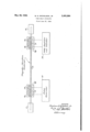
in which the single gure is a diagrammatic illustration of apparatus in accordance with my invention.
Referring now more particularly to the drawing, i0 indicates a rod or wire ci any suitable rod or wire it may be supported in any suitable manner, but preferably are provided with dampl y ing material so that sound waves reaching the The ends of the gli may be obtained when the ends of the rod or wire are imbedded in blocks oi beeswax, as indicated at il and i2.
Adjacent to one end of 'the rod there may be provided'a coil id surrounding the rod or wire, and which I term the transmitting coil. This coil may be enclosed within a shielding grounded container i6 partly-broken away to show the coll. A permanent magnet i3 is diagrammatically indicated, to keep the rod or wire magnetizeci suilciently to retain good magneto-striction conversion.
The coil i5 may be supplied with direct current pulses from a pulse generator i9 of any suitable type. Aswill be-understood, when a direct current is passed through the coil i5, there occurs `a momentary lengthening or shortening of the rod or wire ld, depending on the direction of current flow. This momentary distortion in the length oi the rod or wire l@ at the-point of coil i5 then travels down the rod in opposite directions as a sound wave, and its speed oi travelv is equal to the velocity of sound in the particular material at the particular temperature.
The waves reaching the block of beeswax ii are absorbed or damped out to such a degreeA that no troublesome reiiection occurs. The sound wave may be detected at any point in the rod or" wire it? by the use of a pick-up which may comprise coil'ii surrounding the rod or wire iii and feeding a suitable amplifier 2i) and indicator. In this case, as in the transmitter section, a permarient magnet iii is diagrammatically indicated for the purpose oi? keeping the rod magnetized sumclently to retain good magneto-striction conversion, and the coilL ill may be enclosed within a shielded and grounded container itl shown partly broken away.
As the sound wave produced by a .current pulse in coil ib travels through lcoil il, as will be understood, it generates an electromotive force in coil li which maybe amplified to any suitable extent by the pulse amplifier il@ and applied to any suitable indicating apparatus, such as an oscilloscope.
The rod may be calibrated in units of time or (for radar use) in unitsof miles, the latter being derived by multiplying the speed of light by the particular time interval.
The entire detecting assembly, consisting of the coil il, magnet id, and shielding container it, may be movable on the rod or wire it, and it will be understood that byv moving the same closer to the transmitting end. the time interval is made smaller, andby moving it away the time interval v ismade larger.
In one application of my invention, in measuring the distance to an obiect, as in radar, when the transmitted wave is sent out, a pulse is passed into the coil I5. The receiving coil assembly may then be moved back andforth upon the rod I until the radio echo occurs at the same time that the pulse is picked up by coil ii'.
The distance of the object causing the echo may then be determined by reference to the scale on the rod I0, and is equal tothe distance between the coils 'I5 and l1 multiplied by the ratio of'veloeity of radio waves to that of sound waves in the'magneto-striction material, the whole divided by 2, since the distance to the object is half of the total path of the radio waves to the obi ect and return.
In this connection, it may be noted that the accuracy obtainable in the measurement of. time intervals with apparatus according to my invention is a good deal better than the accuracy of other factors entering into this computation.
While I have indicated that coil I1 may be movable lengthwise of the rod or wire 10, the coil I5 may also be made movable, if desired, and the4 same result maybe obtained by varying the con nui-cunning sam member and spaced from' being otherwise isolated therefrom to prevent feedback thereto and an indicator associated with said receivingcoil. i Y y 4. In time measuring apparatus, in combination, an aperiodic elongated member of magnetostriction material, a transmitting coil surrounding said member, means for impressing a current in said coil to produce a wave traveling longitudinally of said elongated member, a receiving coil surrounding said member and spaced from said transmittingv coil, said receiving coil being fed forwardly from said transmitting coil and being otherwise isolated therefrom to prevent feedback thereto and an indicatorassociated with said receiving coil, one of said coils being movable longitudinally of said member.
5. In time measuring apparatus, in combinal tion, an. aperiodic elongated member of magnetostriction material, a transmittingA coil associated with said member, means for impressing a cura rentl in said coil to produce a Wave traveling longitudinally of said elongated member, a receiving coil associated with said member and spaced position of coil l5 while permitting coil I1 to remain at the same point.
rn this application I have particularly pointed out and distinctly claimed the part, improvement, or'combination which I claim as my invention or discovery, and I have explained the principles thereof and the best mode in which I have contemplated applying tho principles so as to distinguish `my invention from other inventions.
While I have shown and described certain preferred embodiments of my invention, it will be understood that modifications and changes mayy be made without departingv from the spirit and scope thereof, as will be clear to those skilled in the art.
Iclaim:
l. In time measuring apparatus, in combination, an aperiodic elongated member of magnetostriction material, a transmitting coil associated with said member, means for impressing a current in said coil to kproduce a wave traveling longitudinally of said eiognated member, a receiving coil associated with said member and spacedfrom said transmitting coil, said receiving coil being fed forwardly from said transmitting to prevent feedback thereto and. an indicator associated with said receiving coil.
2. In time measuring apparatus, in combination, an aperiodic elongated member of magnetostriction material, a transmitting coil associated with said member, means for impressing a current in said coil to produce a wave traveling longitudinally of said elongated member, a receiving coil associated with said member and spaced from said transmitting coil, said receiving coil being fed forwardly from said transmitting coil and being otherwise isolated therefrom to prevent feedback thereto and an indicator associate'd with said receiving coil,one of said coils being movable longitudinally of said member.
3. In time measuring apparatus. in mbina- 7 being otherwise isolated therefrom to prevent tion, s n aperiodic elongated member of magnetostriction material, a transmitting coil surrounding lsaid member, means for impressing a current in said coil to produce a wave traveling longitudinally of said elongated member, a receiving coil and being otherwise isolated therefrom' from said transmitting coil, said receiving coil being fed forwardly from said transmitting coil and being otherwise isolated therefrom to prevent feedback thereto and an indicator associated with said receiving coil, one of said coils being movable longitudinally of said member, said elongated member having its ends provided with damping material to reduce harmful reilection of waves therefrom. I 6. Intime measuring apparatus, in lcombinal tion, an aperiodic elongated member of magnetostriction material, a transmitting coil associated with said member, means for impressing a cur\ rent in said coil to produce a wave traveling longitudinally of said elongated member, a receiving coil associated with said member and spaced from said transmitting coil, and an indicator associated with said receiving coil. said receiving coil being fed forwardly from said transmitting coil and being otherwise isolated therefrom to prevent 4feedback thereto one of said coils being movable longitudinally of said member, said elongated member having its ends provided with damping material to reduce harmful reflection of waves therefrom.
7. In time delay apparatus, in combination, an aperiodic elongated member of magneto-striction material, means for applying a magneto-striction impulse at one point on said member to produce to produce a sound -wave therein, and means for detecting said sound wave at another`point on said member, one of said means being movable along said member said detecting means being fed forwardly from said applying means and feedback thereto.
9. In time delay apparatus, in combination, an aperiodic elongated member of magneto-striction material, means for applying a magneto-striction impulse at one point on said ymember to'produce a sound wave therein, and meansyfor detecting said sound wave at another point on said member, one of said means beingmovable along said member, said member having means at its ends for reducing reections from said ends said detecting means being fed forwardly from said applying means and being otherwise isolated therefrom to prevent feedback thereto.
10. The method of measuring a range of short time intervals, which comprises magnetically generating a sound wave in an elongated path having magneto-striction properties, and electrically detecting said sound wave at a point on said path removed from the point-of origin of point of transmission except for forward feed in said path.
11. The method of producing time delays of predetermined length which comprises producing a timing current impulse, impressing said impulse upon an elongated path having magnetostriction characteristics to generate a sound wave in said path, electrically detecting said sound wave at another point on said path, andcontrolling the distance between said points to control the' time interval between initiation and detection of said sound Wave While 4maintaining the point of detection of said soundwave isolated from the point of transmission except, for forsaid sound wave while maintaining lthe point of 15 ward feed in said path.
detection of said sound Wave isolated from the MADISON G. NICHOLSON, JR.
Priority Applications (1)
| Application Number | Priority Date | Filing Date | Title |
|---|---|---|---|
| US541743A US2401094A (en) | 1944-06-23 | 1944-06-23 | Time delay apparatus |
Applications Claiming Priority (1)
| Application Number | Priority Date | Filing Date | Title |
|---|---|---|---|
| US541743A US2401094A (en) | 1944-06-23 | 1944-06-23 | Time delay apparatus |
Publications (1)
| Publication Number | Publication Date |
|---|---|
| US2401094A true US2401094A (en) | 1946-05-28 |
Family
ID=24160846
Family Applications (1)
| Application Number | Title | Priority Date | Filing Date |
|---|---|---|---|
| US541743A Expired - Lifetime US2401094A (en) | 1944-06-23 | 1944-06-23 | Time delay apparatus |
Country Status (1)
| Country | Link |
|---|---|
| US (1) | US2401094A (en) |
Cited By (45)
| Publication number | Priority date | Publication date | Assignee | Title |
|---|---|---|---|---|
| US2467301A (en) * | 1945-07-23 | 1949-04-12 | Sperry Prod Inc | Supersonic inspection for flaws lying near the surface of apart |
| US2484034A (en) * | 1945-04-24 | 1949-10-11 | Sperry Corp | Interval measuring system |
| US2495740A (en) * | 1945-07-09 | 1950-01-31 | Standard Telephones Cables Ltd | Magnetostrictive time-delay device |
| US2509545A (en) * | 1945-04-10 | 1950-05-30 | Walton George William | Television system for simultaneously modulating and projecting a plurality of light lines |
| US2512130A (en) * | 1946-04-02 | 1950-06-20 | Us Sec War | Delay means |
| US2526229A (en) * | 1947-11-12 | 1950-10-17 | Hazeltine Research Inc | Magnetostrictive signal-translating arrangement |
| US2540720A (en) * | 1945-08-01 | 1951-02-06 | Forbes Gordon Donald | Transmission line |
| US2549578A (en) * | 1947-12-30 | 1951-04-17 | Hazeltine Research Inc | Magnetostrictive converter time delay device |
| US2559905A (en) * | 1945-09-29 | 1951-07-10 | Raytheon Mfg Co | Electric impulse handling system |
| US2560818A (en) * | 1948-12-29 | 1951-07-17 | Bell Telephone Labor Inc | Visible indicator for radio object locators |
| US2612603A (en) * | 1951-12-15 | 1952-09-30 | Sylvania Electric Prod | Signal-to-noise ratio in pulse reception |
| US2624804A (en) * | 1946-04-02 | 1953-01-06 | David L Arenberg | Solid delay line |
| US2629827A (en) * | 1947-10-31 | 1953-02-24 | Eckert Mauchly Comp Corp | Memory system |
| US2647948A (en) * | 1949-03-30 | 1953-08-04 | Rca Corp | Electromechanical filter |
| US2648060A (en) * | 1945-09-29 | 1953-08-04 | Raytheon Mfg Co | Coded impulse responsive secret signaling system |
| US2696590A (en) * | 1951-06-28 | 1954-12-07 | Rca Corp | Magnetostrictive filter device |
| US2718637A (en) * | 1951-07-27 | 1955-09-20 | Rca Corp | Radar moving target indication system |
| US2750567A (en) * | 1952-03-15 | 1956-06-12 | Rca Corp | Mechanical resonator termination |
| US2754481A (en) * | 1952-08-09 | 1956-07-10 | Hazeltine Research Inc | Electrostrictive time-delay signaltranslating device |
| US2762985A (en) * | 1952-09-20 | 1956-09-11 | Rca Corp | Mechanically resonant filter devices |
| US2815490A (en) * | 1951-03-28 | 1957-12-03 | Itt | Electromechanical delay device |
| US2837721A (en) * | 1952-02-22 | 1958-06-03 | Elliott Brothers London Ltd | Means for delaying electric impulses |
| US2846654A (en) * | 1952-06-25 | 1958-08-05 | Burroughs Corp | Magnetostrictive delay line |
| US2863121A (en) * | 1957-06-25 | 1958-12-02 | Byford Labs Inc | Magnetostrictive pulse-time modulator |
| US2888666A (en) * | 1953-09-16 | 1959-05-26 | Burroughs Corp | Input buffering system |
| US2914757A (en) * | 1952-10-24 | 1959-11-24 | Millership Ronald | Apparatus for generating coded patterns of electric pulses |
| US2962710A (en) * | 1954-06-07 | 1960-11-29 | Cook Electric Co | System and apparatus for measuring intervals |
| US3003239A (en) * | 1955-02-26 | 1961-10-10 | Erich Hoffmann | Method and apparatus for measuring lengths by means of sound waves |
| US3121955A (en) * | 1960-07-08 | 1964-02-25 | United Aircraft Corp | Ultrasonic distance scaling apparatus |
| DE1182368B (en) * | 1953-05-07 | 1964-11-26 | Kelvin & Hughes Ltd | Ultrasonic delay device for measuring purposes |
| US3223981A (en) * | 1962-01-17 | 1965-12-14 | Logitek Inc | Long term timing device and pulse storage system |
| DE1247387B (en) * | 1962-05-07 | 1967-08-17 | Ibm | Converter for an electroacoustic delay line |
| US3365799A (en) * | 1965-01-13 | 1968-01-30 | Honeywell Inc | Angular position measuring device |
| US3389274A (en) * | 1965-12-06 | 1968-06-18 | Perkin Elmer Corp | Peristaltic actuator |
| US3423673A (en) * | 1965-07-13 | 1969-01-21 | Hazeltine Research Inc | Apparatus utilizing magnetostrictive member for measuring linear displacement between two bodies |
| US3898555A (en) * | 1973-12-19 | 1975-08-05 | Tempo Instr Inc | Linear distance measuring device using a moveable magnet interacting with a sonic waveguide |
| US3904821A (en) * | 1973-12-05 | 1975-09-09 | Summagraphics Corp | Position determination devices |
| US4071818A (en) * | 1975-11-03 | 1978-01-31 | Combustion Engineering, Inc. | Magnetostrictive position indicator |
| FR2380671A1 (en) * | 1977-02-10 | 1978-09-08 | Sony Corp | VARIABLE TIMING DEVICE |
| FR2462256A1 (en) * | 1979-07-30 | 1981-02-13 | Pennel Et Flipo | High frequency welding bars with fixed travel limit bars - for welding of thin thermoplastic sheet |
| US4852406A (en) * | 1986-07-11 | 1989-08-01 | Usinor Aciers | Method and apparatus for determining the coefficient of internal friction of steel or the like |
| US4931729A (en) * | 1987-12-22 | 1990-06-05 | Allied-Signal Inc. | Method and apparatus for measuring strain or fatigue |
| US5017867A (en) * | 1989-12-08 | 1991-05-21 | Magnetek Controls | Magnetostrictive linear position detector with reflection termination |
| US5050430A (en) * | 1990-06-19 | 1991-09-24 | Magnetek Controls | Magnetostrictive linear position detector with temperature sensors |
| US20070240504A1 (en) * | 1995-05-11 | 2007-10-18 | Mts Systems Corporation | Isolated magnetostrictive buffered liquid level sensor |
-
1944
- 1944-06-23 US US541743A patent/US2401094A/en not_active Expired - Lifetime
Cited By (47)
| Publication number | Priority date | Publication date | Assignee | Title |
|---|---|---|---|---|
| US2509545A (en) * | 1945-04-10 | 1950-05-30 | Walton George William | Television system for simultaneously modulating and projecting a plurality of light lines |
| US2484034A (en) * | 1945-04-24 | 1949-10-11 | Sperry Corp | Interval measuring system |
| US2495740A (en) * | 1945-07-09 | 1950-01-31 | Standard Telephones Cables Ltd | Magnetostrictive time-delay device |
| US2467301A (en) * | 1945-07-23 | 1949-04-12 | Sperry Prod Inc | Supersonic inspection for flaws lying near the surface of apart |
| US2540720A (en) * | 1945-08-01 | 1951-02-06 | Forbes Gordon Donald | Transmission line |
| US2559905A (en) * | 1945-09-29 | 1951-07-10 | Raytheon Mfg Co | Electric impulse handling system |
| US2648060A (en) * | 1945-09-29 | 1953-08-04 | Raytheon Mfg Co | Coded impulse responsive secret signaling system |
| US2512130A (en) * | 1946-04-02 | 1950-06-20 | Us Sec War | Delay means |
| US2624804A (en) * | 1946-04-02 | 1953-01-06 | David L Arenberg | Solid delay line |
| US2629827A (en) * | 1947-10-31 | 1953-02-24 | Eckert Mauchly Comp Corp | Memory system |
| US2526229A (en) * | 1947-11-12 | 1950-10-17 | Hazeltine Research Inc | Magnetostrictive signal-translating arrangement |
| US2549578A (en) * | 1947-12-30 | 1951-04-17 | Hazeltine Research Inc | Magnetostrictive converter time delay device |
| US2560818A (en) * | 1948-12-29 | 1951-07-17 | Bell Telephone Labor Inc | Visible indicator for radio object locators |
| US2647948A (en) * | 1949-03-30 | 1953-08-04 | Rca Corp | Electromechanical filter |
| US2815490A (en) * | 1951-03-28 | 1957-12-03 | Itt | Electromechanical delay device |
| US2696590A (en) * | 1951-06-28 | 1954-12-07 | Rca Corp | Magnetostrictive filter device |
| US2718637A (en) * | 1951-07-27 | 1955-09-20 | Rca Corp | Radar moving target indication system |
| US2612603A (en) * | 1951-12-15 | 1952-09-30 | Sylvania Electric Prod | Signal-to-noise ratio in pulse reception |
| US2837721A (en) * | 1952-02-22 | 1958-06-03 | Elliott Brothers London Ltd | Means for delaying electric impulses |
| US2750567A (en) * | 1952-03-15 | 1956-06-12 | Rca Corp | Mechanical resonator termination |
| US2846654A (en) * | 1952-06-25 | 1958-08-05 | Burroughs Corp | Magnetostrictive delay line |
| US2754481A (en) * | 1952-08-09 | 1956-07-10 | Hazeltine Research Inc | Electrostrictive time-delay signaltranslating device |
| US2762985A (en) * | 1952-09-20 | 1956-09-11 | Rca Corp | Mechanically resonant filter devices |
| US2914757A (en) * | 1952-10-24 | 1959-11-24 | Millership Ronald | Apparatus for generating coded patterns of electric pulses |
| DE1182368B (en) * | 1953-05-07 | 1964-11-26 | Kelvin & Hughes Ltd | Ultrasonic delay device for measuring purposes |
| US2888666A (en) * | 1953-09-16 | 1959-05-26 | Burroughs Corp | Input buffering system |
| US2962710A (en) * | 1954-06-07 | 1960-11-29 | Cook Electric Co | System and apparatus for measuring intervals |
| US3003239A (en) * | 1955-02-26 | 1961-10-10 | Erich Hoffmann | Method and apparatus for measuring lengths by means of sound waves |
| US2863121A (en) * | 1957-06-25 | 1958-12-02 | Byford Labs Inc | Magnetostrictive pulse-time modulator |
| US3121955A (en) * | 1960-07-08 | 1964-02-25 | United Aircraft Corp | Ultrasonic distance scaling apparatus |
| US3223981A (en) * | 1962-01-17 | 1965-12-14 | Logitek Inc | Long term timing device and pulse storage system |
| DE1247387B (en) * | 1962-05-07 | 1967-08-17 | Ibm | Converter for an electroacoustic delay line |
| US3365799A (en) * | 1965-01-13 | 1968-01-30 | Honeywell Inc | Angular position measuring device |
| US3423673A (en) * | 1965-07-13 | 1969-01-21 | Hazeltine Research Inc | Apparatus utilizing magnetostrictive member for measuring linear displacement between two bodies |
| US3389274A (en) * | 1965-12-06 | 1968-06-18 | Perkin Elmer Corp | Peristaltic actuator |
| US3904821A (en) * | 1973-12-05 | 1975-09-09 | Summagraphics Corp | Position determination devices |
| US3898555A (en) * | 1973-12-19 | 1975-08-05 | Tempo Instr Inc | Linear distance measuring device using a moveable magnet interacting with a sonic waveguide |
| US4071818A (en) * | 1975-11-03 | 1978-01-31 | Combustion Engineering, Inc. | Magnetostrictive position indicator |
| FR2380671A1 (en) * | 1977-02-10 | 1978-09-08 | Sony Corp | VARIABLE TIMING DEVICE |
| FR2462256A1 (en) * | 1979-07-30 | 1981-02-13 | Pennel Et Flipo | High frequency welding bars with fixed travel limit bars - for welding of thin thermoplastic sheet |
| US4852406A (en) * | 1986-07-11 | 1989-08-01 | Usinor Aciers | Method and apparatus for determining the coefficient of internal friction of steel or the like |
| US4931729A (en) * | 1987-12-22 | 1990-06-05 | Allied-Signal Inc. | Method and apparatus for measuring strain or fatigue |
| US5017867A (en) * | 1989-12-08 | 1991-05-21 | Magnetek Controls | Magnetostrictive linear position detector with reflection termination |
| US5050430A (en) * | 1990-06-19 | 1991-09-24 | Magnetek Controls | Magnetostrictive linear position detector with temperature sensors |
| US20070240504A1 (en) * | 1995-05-11 | 2007-10-18 | Mts Systems Corporation | Isolated magnetostrictive buffered liquid level sensor |
| US7737684B2 (en) | 1995-05-11 | 2010-06-15 | Mts Systems Corporation | Isolated magnetostrictive buffered liquid level sensor |
| US8044657B2 (en) | 1995-05-11 | 2011-10-25 | Mts Systems Corporation | Isolated magnetostrictive buffered liquid level sensor |
Similar Documents
| Publication | Publication Date | Title |
|---|---|---|
| US2401094A (en) | Time delay apparatus | |
| US4125835A (en) | Range or time-delay determining subsystem for use in certain radar-like systems | |
| US2562450A (en) | Pulse cutoff device | |
| US2429623A (en) | Pulse distance measuring system | |
| US3754472A (en) | Apparatus for analysing by means of ultrasonic pulses, employing the reflecting profile characteristic of each obstacle | |
| JPS57131085A (en) | Ultrasonic wave measuring system | |
| US2448399A (en) | Supersonic inspection | |
| Serafin et al. | Measurement of strain and velocity of ultrasonic surface waves | |
| SU1420518A1 (en) | Apparatus for measuring ultrasound velocity in a material | |
| US3538751A (en) | Direct reading ultrasonic thickness gage | |
| SU930169A1 (en) | Method of location of communication line damage | |
| RU2037848C1 (en) | Method and device for measuring distances | |
| SU970213A1 (en) | Device for material acoustic emission checking | |
| RU2189111C2 (en) | Displacement measurement technique | |
| SU456996A1 (en) | The method of controlling the physical parameters of liquids | |
| RU2052767C1 (en) | Method of measuring linear motion of objects | |
| SU1307325A1 (en) | Meter of ultrasound velocity | |
| SU1518779A1 (en) | Method of checking physico-mechanical properties of material | |
| SU785742A1 (en) | Ultrasonic flaw detector | |
| SU366766A1 (en) | Ultrasonic flaw detector | |
| SU1252667A1 (en) | Method and apparatus for measuring shifts | |
| SU585409A1 (en) | Apparatus for calibration of ultrasonic flowmeters | |
| RU1820230C (en) | Device for measuring speed of propagation of ultrasonic oscillations | |
| SU1161924A1 (en) | Device for controlling batch-weighing scale | |
| SU800632A2 (en) | Magnetoacoustic thickness gauge |