US2394635A - Magnifying lens system - Google Patents
Magnifying lens system Download PDFInfo
- Publication number
- US2394635A US2394635A US544700A US54470044A US2394635A US 2394635 A US2394635 A US 2394635A US 544700 A US544700 A US 544700A US 54470044 A US54470044 A US 54470044A US 2394635 A US2394635 A US 2394635A
- Authority
- US
- United States
- Prior art keywords
- positive
- negative
- lens system
- magnifying lens
- lens
- Prior art date
- Legal status (The legal status is an assumption and is not a legal conclusion. Google has not performed a legal analysis and makes no representation as to the accuracy of the status listed.)
- Expired - Lifetime
Links
- 150000001875 compounds Chemical class 0.000 description 9
- 206010010071 Coma Diseases 0.000 description 2
- 201000009310 astigmatism Diseases 0.000 description 2
- 230000005499 meniscus Effects 0.000 description 2
- 230000003287 optical effect Effects 0.000 description 2
- 230000004075 alteration Effects 0.000 description 1
- 239000005331 crown glasses (windows) Substances 0.000 description 1
- 239000005308 flint glass Substances 0.000 description 1
- 239000011521 glass Substances 0.000 description 1
- 239000002184 metal Substances 0.000 description 1
- 230000000717 retained effect Effects 0.000 description 1
- 238000001228 spectrum Methods 0.000 description 1
Images
Classifications
-
- G—PHYSICS
- G02—OPTICS
- G02B—OPTICAL ELEMENTS, SYSTEMS OR APPARATUS
- G02B25/00—Eyepieces; Magnifying glasses
- G02B25/002—Magnifying glasses
- G02B25/008—Magnifying glasses comprising two or more lenses
Definitions
- This invention relates to magnifying' lenses.
- An object of the invention is to provide a magnifying lens with a large field of view and a large working distance between lens and object plane, and convenient to use even when made up in a focal length shorter than 60 mm.
- Another object of the invention is to provide a magnifying lens system which possesses these advantages and which is convertible so that a part of the system forms a higher power magnifier with a shorter working distance.
- the present invention on the other hand gives up to at least 6X magnification without appreciable loss of image quality.
- F is the focal length of the system is made up consisting of a front positive member facing the object plane and a rear negative member facing the eyepoint such that the positive member comprises at least two positive components of which the front one is biconvex and the rear one is meniscus concave toward the rear end of which at least one is compound and comprises a positive element cemented to a negative element the index of refraction of which is at least 0.01 greater than that of the positive element; the negative rmember comprises a compound biconcave component, and the two members are spaced apart more than 1A; F and less than 1/2 F.
- compound componen a component consisting of two or more elements, at least one being of each sign, the element or elements having the same sign as the whole com- 10 ponent being made of crown glass and the others of flint glass or their equivalents so as to correct the chromatic aberration.
- two components of the positive member are compound and each comprises a positive element and a negative element cemented thereto whose refractive index is at least 0.01 greater on the average than that of the positive element.
- Each of the two cemented surfaces thus has negative power.
- the two positive compound components beso arranged that the two positive elements are located between the two neagtive elements.
- the index difference at the (negative) cemented surfaces should be less than 0.07. Otherwise the field curvature tends to be over-corrected.
- Certain other arrangements are practical in which this index difference is advantageously greater than this and in fact may be as large as available glass types permit. I have found the preferred arrangement to be superior, however.
- the rear surface of the front positive component be more strongly curved than the front surface of said component, in order to minimize the distortion of the system.
- the negative member is detachably positive member alone being excellent as an ordinary magnifier of still higher power.
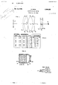
- Fig. 1 shows an axial cross section of the optical elements of a. lens system according to the invention.
- FIG. 3 showsua convertible magnifying lens system similar to that shown in Figs. 1 and 2.
- the two positive components 3l, 32 are mounted in the tube 33, spacedby a ring 34, and retained by a threaded ring 35.
- the tube 33 is threaded at one end to take the retaining ring 35 and at the other end to take the mount 36 of the negative component 31.
- the negative component is shown as held in its mount by a retaining ring 38.
- F is the focal length of the lens system and consisting of a front positive member facing the object plane and a rear negative member facing the eye point, in which the positive member comprises at least two positive components of which the iront one is biconvex and the rear one is meniscus concave toward the rear end o!
- the negative member comprises a compound biconcave component, and the two members are spaced apart more than 1/3 F and less than 1/2 F.
- a lens system according to claim 1 in which two components of the positive member are compound and each comprises a positive element and a negative element cemented thereto whose refractive indexis at least 0.01 greater on the average than that of the positive element.
- a lens system according to claim 1 in which two components ofthe positive member are compound and each comprises a positive element and a negative element cemented thereto whose refractive index is on the average at least 0.01 greater than that of the positive element, the two said positive elements being located between the two said negative elements.
- a lens system according to claim 1 in which the positive member consists entirely of two achromatic doublets in which the two cemented surfaces have negative power.
- a lens system according to claim 1 in which the positive member consists of two achromatic doublets in which the two cemented surfaces are concave toward each other and have negative power.
- a magniiier lens having approximately the following specifications:
- N is the index of refraction for the D line of the spectrum
- V is the dispersive index
- R, t, and s are the radii of surface curvature, thicknesses and air spaces from front to rear
- F is the focal length of the lens and and signs indicate surfaces respectively convex and concave to the iront.
Landscapes
- Physics & Mathematics (AREA)
- General Physics & Mathematics (AREA)
- Optics & Photonics (AREA)
- Lenses (AREA)
Description
UNITED. STATES SMTCII KOU PATENT OFFICEl MAGNIFYING LENS SYSTEM Max Reiss, Rochester, N. Y., assignor to Eastman Kodak Company, Rochester, N. Y., a corporation of New Jersey Application July 13, 1944, Serial No. 544,700
7 Claims.
This invention relates to magnifying' lenses.
An object of the invention is to provide a magnifying lens with a large field of view and a large working distance between lens and object plane, and convenient to use even when made up in a focal length shorter than 60 mm.
Another object of the invention is to provide a magnifying lens system which possesses these advantages and which is convertible so that a part of the system forms a higher power magnifier with a shorter working distance.
'I'he use of a negative member spaced from a positive member for the purpose of shifting the nodal points and increasing the focal distance on the other side of the positive member relative to the equivalent focal length is known in the field of telephoto and wide-angle objectives or attachments and other related fields.
Some attempts have been made to employ this arrangement in a magnifying lens system. Even though it is widely recognized that the utility of such a lens would be great and the applications many, the results have been discouraging and the feeling has been prevalent that a 3X magnification is about the best that could be looked for in such a system if it is to cover a useful field of view.
The present invention on the other hand gives up to at least 6X magnification without appreciable loss of image quality.
According to the present invention, a telephoto-type magnifying lens system corrected for coma, curvature of field, astigmatism and lateral color over a, field of view of more than 9 from the axis and for an eyepoint distance in air of at least 0.2 F where F is the focal length of the system is made up consisting of a front positive member facing the object plane and a rear negative member facing the eyepoint such that the positive member comprises at least two positive components of which the front one is biconvex and the rear one is meniscus concave toward the rear end of which at least one is compound and comprises a positive element cemented to a negative element the index of refraction of which is at least 0.01 greater than that of the positive element; the negative rmember comprises a compound biconcave component, and the two members are spaced apart more than 1A; F and less than 1/2 F.
The combination of all these features results in a superior magnifying lens with a, large working distance, which can -be made up in a focal length shorter than 60 mm., thus giving a magnification greater than 4X, and still be convenient 55 to use without setting the eye uncomfortably close to the lens and without moving the eye about when examining the magnified image of the object field.
It will be readily understood by all skilled in the art that by compound componen is meant a component consisting of two or more elements, at least one being of each sign, the element or elements having the same sign as the whole com- 10 ponent being made of crown glass and the others of flint glass or their equivalents so as to correct the chromatic aberration.
According to a. further development of the in-l vention, two components of the positive member are compound and each comprises a positive element and a negative element cemented thereto whose refractive index is at least 0.01 greater on the average than that of the positive element. Each of the two cemented surfaces thus has negative power.
It is preferred that the two positive compound components beso arranged that the two positive elements are located between the two neagtive elements. When this preferred arrangement is used, the index difference at the (negative) cemented surfaces should be less than 0.07. Otherwise the field curvature tends to be over-corrected. Certain other arrangements are practical in which this index difference is advantageously greater than this and in fact may be as large as available glass types permit. I have found the preferred arrangement to be superior, however.
It is advantageous that the rear surface of the front positive component be more strongly curved than the front surface of said component, in order to minimize the distortion of the system.
It is also advantageous in the preferred embodiment to have the average radius of curvature of the two cemented surfaces greater than threequarters of the focal length of the positive member.
According to still another feature of the invention, the negative member is detachably positive member alone being excellent as an ordinary magnifier of still higher power.
In the accompanying drawing:
Fig. 1 shows an axial cross section of the optical elements of a. lens system according to the invention.
EF- 100.0 Angular iield=l2 Lens N V Radii Thicknesses I l. 05 34 )2l-+138 mm. t1=7 mm.
II 1. 61 59 Rz+73 z-22 RIS -mZ 51:0.2
III 1.62 60 R4+91 tx==29 IV 1.65 34 Rr--73 tw? V 1. 62 55 .R1- 107 i524 VI 1. 62 37 R|+73 t|=5 Iig-+270 Fig. 3 showsua convertible magnifying lens system similar to that shown in Figs. 1 and 2. The two positive components 3l, 32 are mounted in the tube 33, spacedby a ring 34, and retained by a threaded ring 35. The tube 33 is threaded at one end to take the retaining ring 35 and at the other end to take the mount 36 of the negative component 31. The negative component is shown as held in its mount by a retaining ring 38. Alternatively it maybe spun in, that is a thin edge of metal may be bent over around its periphery to hold it in. By screwing the negative lens mount 36 into the lens tube 33 the telephoto magniiier'is assembled, and by unscrewing these parts and using only the positive components it is converted into a higher power ordinary magnifier in accordance with one feature of the invention.
Reference is made to the description of this. magnifying lens I published under the title The Design of a Telephoto Magnifier" in the Journal ofthe Optical Society of America, vol. 33, No. l2, 641-651, December 1943.
What I claim is:
l. A telephoto-type magnifying lens system corrected for coma, curvature of field, astigmatism, and lateral color over a. field of view of at least 9 from the axis and for an eye point distance in air of at least 0.2 F where F is the focal length of the lens system and consisting of a front positive member facing the object plane and a rear negative member facing the eye point, in which the positive member comprises at least two positive components of which the iront one is biconvex and the rear one is meniscus concave toward the rear end o! which at least one is compound and comprises a positive element cemented to a negative element whose index of refraction is at least 0.01 greater than that of the positive element, the negative member comprises a compound biconcave component, and the two members are spaced apart more than 1/3 F and less than 1/2 F.
2. A lens system according to claim 1 in which two components of the positive member are compound and each comprises a positive element and a negative element cemented thereto whose refractive indexis at least 0.01 greater on the average than that of the positive element.
3. A lens system according to claim 1 in which two components ofthe positive member are compound and each comprises a positive element and a negative element cemented thereto whose refractive index is on the average at least 0.01 greater than that of the positive element, the two said positive elements being located between the two said negative elements.
4. A lens system according to claim 1 in which the positive member consists entirely of two achromatic doublets in which the two cemented surfaces have negative power.
5. A lens system according to claim 1 in which the positive member consists of two achromatic doublets in which the two cemented surfaces are concave toward each other and have negative power.
6. A lens system according to claim 1 in which the negative member consists of a biconcave achromatic cemented doublet.
7. A magniiier lens having approximately the following specifications:
where the first column numbers the elements from front to rear, N is the index of refraction for the D line of the spectrum, V is the dispersive index, R, t, and s are the radii of surface curvature, thicknesses and air spaces from front to rear, F is the focal length of the lens and and signs indicate surfaces respectively convex and concave to the iront.
MAX REISS.
Priority Applications (1)
| Application Number | Priority Date | Filing Date | Title |
|---|---|---|---|
| US544700A US2394635A (en) | 1944-07-13 | 1944-07-13 | Magnifying lens system |
Applications Claiming Priority (1)
| Application Number | Priority Date | Filing Date | Title |
|---|---|---|---|
| US544700A US2394635A (en) | 1944-07-13 | 1944-07-13 | Magnifying lens system |
Publications (1)
| Publication Number | Publication Date |
|---|---|
| US2394635A true US2394635A (en) | 1946-02-12 |
Family
ID=24173213
Family Applications (1)
| Application Number | Title | Priority Date | Filing Date |
|---|---|---|---|
| US544700A Expired - Lifetime US2394635A (en) | 1944-07-13 | 1944-07-13 | Magnifying lens system |
Country Status (1)
| Country | Link |
|---|---|
| US (1) | US2394635A (en) |
Cited By (9)
| Publication number | Priority date | Publication date | Assignee | Title |
|---|---|---|---|---|
| US2479907A (en) * | 1946-04-03 | 1949-08-23 | Taylor Taylor & Hobson Ltd | Optical objective having a front member correcting spherical aberration, field curvature, and distortion |
| US2502543A (en) * | 1946-12-30 | 1950-04-04 | Taylor Taylor & Hobson Ltd | Highly corrected optical objective with axially spaced spherical aberration correction means |
| US2637245A (en) * | 1949-10-31 | 1953-05-05 | Leitz Ernst Gmbh | Eyepiece for optical instruments |
| US3059532A (en) * | 1959-01-12 | 1962-10-23 | Bell & Howell Co | Optical system |
| US5202795A (en) * | 1990-10-23 | 1993-04-13 | Olympus Optical Co., Ltd. | Eyepieces |
| US5663834A (en) * | 1995-09-12 | 1997-09-02 | Fuji Photo Optical Co. Ltd. | Eyepiece zoom lens system |
| US5701475A (en) * | 1994-08-31 | 1997-12-23 | Canon Kabushiki Kaisha | Eyepiece lens |
| US10371927B2 (en) | 2014-12-30 | 2019-08-06 | Largan Precision Co., Ltd. | Photographing optical lens assembly, image capturing device and electronic device |
| RU191915U1 (en) * | 2019-05-15 | 2019-08-28 | Акционерное общество "ЛОМО" | Ocular with a remote exit pupil |
-
1944
- 1944-07-13 US US544700A patent/US2394635A/en not_active Expired - Lifetime
Cited By (12)
| Publication number | Priority date | Publication date | Assignee | Title |
|---|---|---|---|---|
| US2479907A (en) * | 1946-04-03 | 1949-08-23 | Taylor Taylor & Hobson Ltd | Optical objective having a front member correcting spherical aberration, field curvature, and distortion |
| US2502543A (en) * | 1946-12-30 | 1950-04-04 | Taylor Taylor & Hobson Ltd | Highly corrected optical objective with axially spaced spherical aberration correction means |
| US2637245A (en) * | 1949-10-31 | 1953-05-05 | Leitz Ernst Gmbh | Eyepiece for optical instruments |
| US3059532A (en) * | 1959-01-12 | 1962-10-23 | Bell & Howell Co | Optical system |
| US5202795A (en) * | 1990-10-23 | 1993-04-13 | Olympus Optical Co., Ltd. | Eyepieces |
| US5701475A (en) * | 1994-08-31 | 1997-12-23 | Canon Kabushiki Kaisha | Eyepiece lens |
| US5663834A (en) * | 1995-09-12 | 1997-09-02 | Fuji Photo Optical Co. Ltd. | Eyepiece zoom lens system |
| US10371927B2 (en) | 2014-12-30 | 2019-08-06 | Largan Precision Co., Ltd. | Photographing optical lens assembly, image capturing device and electronic device |
| US11262542B2 (en) | 2014-12-30 | 2022-03-01 | Largan Precision Co., Ltd. | Photographing optical lens assembly, image capturing device and electronic device |
| US11867884B2 (en) | 2014-12-30 | 2024-01-09 | Largan Precision Co., Ltd. | Photographing optical lens assembly, image capturing device and electronic device |
| US12571994B2 (en) | 2014-12-30 | 2026-03-10 | Largan Precision Co., Ltd. | Photographing optical lens assembly, image capturing device and electronic device |
| RU191915U1 (en) * | 2019-05-15 | 2019-08-28 | Акционерное общество "ЛОМО" | Ocular with a remote exit pupil |
Similar Documents
| Publication | Publication Date | Title |
|---|---|---|
| JPH05249371A (en) | Large aperture ratio objective | |
| US2394635A (en) | Magnifying lens system | |
| US4046459A (en) | Retrofocus wide angle objective lens system | |
| JP3735909B2 (en) | Retro focus lens | |
| US2388869A (en) | Photographic objective | |
| US2944464A (en) | Anamorphic lens system | |
| US4251131A (en) | Microscope objective | |
| US2600805A (en) | Telecentric objective of the reversed telephoto type | |
| US2348667A (en) | Optical objective | |
| US4251133A (en) | Large aperture telephoto-lens | |
| US4094587A (en) | Afocal front attachment for zoom objective | |
| US4268128A (en) | Ocular of large visual field | |
| JP3518704B2 (en) | Eyepiece | |
| US2683396A (en) | Optical objective system of the gauss type comprising five airspaced members | |
| US3989317A (en) | Objective lens system | |
| US4279477A (en) | Objective lens system for microscopes | |
| US2399858A (en) | Optical objective | |
| US3038380A (en) | Asymmetrical photographic objective | |
| US2764062A (en) | Three component photographic objective | |
| US2481688A (en) | Large aperture objective having four air spaced components | |
| US2724992A (en) | Photographic objective comprising three axially aligned and air spaced components | |
| US4316653A (en) | Condenser optical system for a microscope | |
| US2836102A (en) | High aperture photographic lens | |
| US2900871A (en) | Magnifier | |
| US2896506A (en) | High aperture wide-angle objective lens |