US2394271A - Suction cleaning apparatus - Google Patents
Suction cleaning apparatus Download PDFInfo
- Publication number
- US2394271A US2394271A US533522A US53352244A US2394271A US 2394271 A US2394271 A US 2394271A US 533522 A US533522 A US 533522A US 53352244 A US53352244 A US 53352244A US 2394271 A US2394271 A US 2394271A
- Authority
- US
- United States
- Prior art keywords
- switch
- casing
- cleaner
- mounting
- handle
- Prior art date
- Legal status (The legal status is an assumption and is not a legal conclusion. Google has not performed a legal analysis and makes no representation as to the accuracy of the status listed.)
- Expired - Lifetime
Links
Images

Classifications
-
- A—HUMAN NECESSITIES
- A47—FURNITURE; DOMESTIC ARTICLES OR APPLIANCES; COFFEE MILLS; SPICE MILLS; SUCTION CLEANERS IN GENERAL
- A47L—DOMESTIC WASHING OR CLEANING; SUCTION CLEANERS IN GENERAL
- A47L9/00—Details or accessories of suction cleaners, e.g. mechanical means for controlling the suction or for effecting pulsating action; Storing devices specially adapted to suction cleaners or parts thereof; Carrying-vehicles specially adapted for suction cleaners
- A47L9/28—Installation of the electric equipment, e.g. adaptation or attachment to the suction cleaner; Controlling suction cleaners by electric means
- A47L9/2889—Safety or protection devices or systems, e.g. for prevention of motor over-heating or for protection of the user
-
- A—HUMAN NECESSITIES
- A47—FURNITURE; DOMESTIC ARTICLES OR APPLIANCES; COFFEE MILLS; SPICE MILLS; SUCTION CLEANERS IN GENERAL
- A47L—DOMESTIC WASHING OR CLEANING; SUCTION CLEANERS IN GENERAL
- A47L9/00—Details or accessories of suction cleaners, e.g. mechanical means for controlling the suction or for effecting pulsating action; Storing devices specially adapted to suction cleaners or parts thereof; Carrying-vehicles specially adapted for suction cleaners
- A47L9/28—Installation of the electric equipment, e.g. adaptation or attachment to the suction cleaner; Controlling suction cleaners by electric means
- A47L9/2836—Installation of the electric equipment, e.g. adaptation or attachment to the suction cleaner; Controlling suction cleaners by electric means characterised by the parts which are controlled
- A47L9/2842—Suction motors or blowers
-
- A—HUMAN NECESSITIES
- A47—FURNITURE; DOMESTIC ARTICLES OR APPLIANCES; COFFEE MILLS; SPICE MILLS; SUCTION CLEANERS IN GENERAL
- A47L—DOMESTIC WASHING OR CLEANING; SUCTION CLEANERS IN GENERAL
- A47L9/00—Details or accessories of suction cleaners, e.g. mechanical means for controlling the suction or for effecting pulsating action; Storing devices specially adapted to suction cleaners or parts thereof; Carrying-vehicles specially adapted for suction cleaners
- A47L9/28—Installation of the electric equipment, e.g. adaptation or attachment to the suction cleaner; Controlling suction cleaners by electric means
- A47L9/2857—User input or output elements for control, e.g. buttons, switches or displays
-
- A—HUMAN NECESSITIES
- A47—FURNITURE; DOMESTIC ARTICLES OR APPLIANCES; COFFEE MILLS; SPICE MILLS; SUCTION CLEANERS IN GENERAL
- A47L—DOMESTIC WASHING OR CLEANING; SUCTION CLEANERS IN GENERAL
- A47L9/00—Details or accessories of suction cleaners, e.g. mechanical means for controlling the suction or for effecting pulsating action; Storing devices specially adapted to suction cleaners or parts thereof; Carrying-vehicles specially adapted for suction cleaners
- A47L9/28—Installation of the electric equipment, e.g. adaptation or attachment to the suction cleaner; Controlling suction cleaners by electric means
- A47L9/2868—Arrangements for power supply of vacuum cleaners or the accessories thereof
Definitions
- the switch controlling the motor and the wiring of the motor terminals to the switch are wholly enclosed within the casing, with the switch-actuating button and the electrical conductors leading to the switch extending through apertures in the wall of said casing. If such apertures are small so as to be easily sealed, access to the switch and wiring can be had only upon removing the adjacent end bell. If apertures big enough to afford access into the interior of the casing are provided, they cannot be properly sealed without elaborate and expensive structure.
- the switch assembly projects through an aperture in the wall of the casing, thus making the sealing of suchaperture difiicult.
- the connection of the motor terminals to the switch terminals is enclosed within the casing so that making the connection between the motor and switch terminals in an original assembly, and the subsequent servicing of such connection during use, are rendered difficult and time consuming.
- a still further object is to devise an improved switch mounting means whereby the complete switch mechanism is located wholly without the casing of the cleaner, so as to be readily accessible, with only the electrical conductor leading from the switch to the motor passing through an opening in the wall of the cleaner casing.
- a still further object of my invention is to produce an improved switch mounting structure in which the switch mounting means is disposed between the top of the casing and a handle extending longitudinally of and above the top of the casing, and in which said switch mounting 10 drical, open-ended body portion, and two end' to each other and to the casing by the same fastening means.
- a still further object is to provide an improved switch mounting device which also includes strain relief for the electric cord of the cleaner.
- a still further object of my invention is to provide an improved suction cleaner of the tank type having only one end bell which is removable for withdrawal and emptying of the filter bag, or for servicing or withdrawal of the motor and fan from the cleaner casing.
- a still further object is to devise an improved switch mounting which will be compact, neat and inexpensive to produce and easy to assemble and. service.
- Fig. 1 is a view ,in side elevation of a suction cleaner embodying my invention
- FIG. 2 is an enlarged fragmentary view in vertical longitudinal section, showing the improved switch-mounting means embodying my invention
- Fig. 3 is a left-hand end elevation of one of the component parts of the switch-mounting means which is shown in top plan view in Fig. 6;
- Fig. 4 is a left-hand end elevational view of the other component part which is shown in top plan view in Fig. '7;
- Fig. 5 is an enlarged sectional view taken on line V-V of Fig. 2, certain parts being omitted for clarity of illustration;
- Fig. 6 is a section taken on line VI-VI of Fig. 2;
- Fig. 7 is a top plan view of the part shown in Fig. 3;
- FIG. 8 is a top plan view of the part shown in Fig. 4;
- Fig. 9 is an enlarged, front elevational view looking in the direction of the line IXIX on Fig. 6; and V Fig. 10 is a view similar to Fig. 2, showing a modified form of construction.
- a tank type cleaner [0 supported on runners II and provided with a handle I2 extending longitudinally of, and in parallel spaced relation to, the top of the cleaner.
- the cleaner I 6 includes a cylindrical, elongated body portion l3 and an end bell l4 detachably secured to the body portion i3 and forming one end of the cleaner casing.
- the end bell I4 is provided with a coupling member to which a hose I may be connected in the usual way.
- the other end of the hose I5 is provided with a suitable nozzle or dusting tool (not shown).
- the other end of the body portion I3 is tapered and provided with an exhaust opening IS.
- the usual motor I1 which drives a fan (not shown) for drawing dirt-laden air through the hose I5 into and through afilter bag, which is also not shown. The filtered air is discharged through the exhaust opening Hi.
- the motor I! is connected to a switch I8 by wires I9 passing through an opening in the top of the casing. Electrical energy is supplied to the motor 11 by an electric cord 2I, provided with a protective sleeve 22 having an enlarged head 23. The cord 2
- Theimproved switch-mounting means includes a mounting block 24 and a closure or cover member 26, which are shown in left-hand end elevation in Figs. 3 and 4 and in top plan view in Figs. 7 and 8; V
- the mounting block 24 is formed of a vertical side wall 28 and enlarged end bosses 3i] and 32.
- the vertical wall 28 and the bosses 30 and 32 form a pocket or recess for accommodating the switch l8.
- The-end bosses 30 and 32 are provided with vertical bores 34 for receiving bolts 36," carried by the handle I4; and adapted to pass through suitable openings in the top of the cleaner.
- the bolts 36 are adapted to be engaged by retaining nuts 38 disposed within the cleaner casing.
- the block 24 is also provided with a horizontal groove 'iormed in the wall 28 and inthe juxtaposed faces of the end bosses 30 and 32.
- the groove 40 is formed at a point substantially halfway between the top and bottom of the mounting block 24, as shown in Figs. 2 and 5.
- the end boss 32 of the mounting block 24 is further provided with a horizontal recess including a portion 44 and a portion 46 which are adapted to accommodate corresponding interfitting projections or bosses on the juxtaposed face of the closure member 26 when the switchmounting means is assembled.
- the recesses 44 and 46 terminate in an inner arcuate wall which forms a seat for the electric cord and its protective'sleeve.
- the seat referred'to includes a portion 50 for accommodating the body of the sleeve 22, a portion 52 for accommodating the enlarged head 23 of the sleeve, and a portion 54 for accommodating the cord 2!.
- the end boss 38 of the. mounting block 24 is provided with a recess 48, also adapted to receive a corresponding projection on. th juxtaposed side of the closure member 26.
- the closure member 26 includes a vertical. side wall 58 whichis recessed toform a horizontal shelf or shoulder 60, coextensive and in horizontal alignment with the groove 40 in the block 24.
- the closure member 25 includes bosses 62, 64 and ES, which when the mounting meansis assembled, enter recesses '44, 45 and'48'with the shoulder 65 and the boss 65 abutting'against the'vertical surfaces Stand 69' of the bosses 30- and 321 The The portion. 54
- bosses 62 and 64 are provided with a horizontal recess including portions 5!, 53 and 55 which are complementary to the seat portions 50, 52 and 54, respectively, of th recess in the boss 32. See Figs. I and 8.
- the wall of the recess 55' is provided with beads 51 which are complementary to the beads 55 on the wall of the recess 54.
- the mounting block 24 and the closure 26 are clamped together by screws ID passing through countersunk openings 12 in the wall 28 of the closure member 26, and engaging threaded holes I4 in the juxtaposed faces of the bosses 30 and 32 of the block 24.
- the lower portions of the side walls 28 and 58 r are recessed to form oppositely-disposed grooves 15 and i8, and are provided with humps or projections 8! ⁇ and 82 which begin at a point below the groove 49 in the wall 28 and shelf Bil in the wall 58 and terminate just above the grooves Hi and I3, as clearly shown in Fig. 5.
- the switch-operating button is provided with an inverted cup-shaped cover I52 which extends upwardly through an opening I04, formed in the handle I2, and is provided with an enlarged lower rim IBE.
- the enlarged lower riin HIE prevents the cover I82 from being withdrawn throughthe opening Ind, and bears against the adjacent side of the boss 35 and the adjacent side of a guard I38 carried by the wall 28 of the block 24, to guide the button 90 in its vertical movement in turning the switch on or off?
- the wires I9 are passed through relatively tight apertures formed in a grommet 96, which may be of rubber or the like and which has a flange I98 engaging the upper rim of the opening 20:
- the switch ,plate 92, carrying the switch I8 and the switch operating button 99 is inserted along three sides thereof into the groove 4
- the cover I02 is then placed on the switch button 90 and the block 24, carrying the parts thus far described, is placed on top-of the cleaner casing.
- the handle I2 is then placedron top of the block 24 with .the bolts 3t thereof. extending through the bores throughthe'apertures in the grommetfor connection to the terminals of the switch I8. The grommet.
- the Closure member 25 is placed on top of the cleaner in contiguous juxtaposition to the mounting block 25 and is clamped thereto by the screws 70.
- the portion of the flange IEO adjacent the wall 53 of the closure member engages the recess l8 and is squeezed between the lower portion of the hump 32 and the top of the casing to insure a tight joint between that portion of the flange and the top of the casing.
- the fourth side of the switch plate 92 or the side thereof adjacent the closure member 2 5 is, as shown in Fig. 5, supported on the ledge or shelf 66 formed in the wall 58 of the closure member 25.
- Fig. 9 there is shown a modified form of construction which is identical With that shown in the preceding figures, exceptthat the switch plate 92, the groove 4-8 and the shelf Bil are omitted.
- the switch [8 is provided With a threaded portion H5 adapted to engage a threaded opening H8 in the handle l2 and is retained in position by a nut I26. Except for this difierence, the structure is exactly as that shown in Figs. 1 to 8 and is, therefore, not shown or described in detail.
- the switch and all of its connections are mounted exteriorly of the cleaner casing and that the same are accessible for inspection and servicing upon disengagement of the closure member 2-6 from the mounting block 2 3.
- the opening 29 is adequately and easily sealed by the rommet 93, the body portion of which fits tightly in the opening 28 and the flange of which is tightly clamped between the hump portions 8d and 82 and the top of the casing.
- a suction cleaner a casing, a handle for said cleaner, a mounting block disposed between said casing and said handle and having a recess therein, means for securing said handle and said block to said casing, a switch for controlling the supply of electrical energy to said cleaner, said switch being mounted in said recess, there being an opening in the wall of said casing communicating with said recess and through which wires leading from the terminals of said switch are adapted to pass, an electric cord for supplying electrical energy to said switch, a closure member for closing said recess, and means for securing said closure member to said block, there being complementary recesses in the juxtaposed, contiguous walls of said mounting block and said closure member forming a bore through which m invention in several plate.
- a suction cleaner a casing, a handle extending above said casing, there being an opening in said handle, a switch for controlling the supply of electrical energy to said cleaner, an operating button for said switch movable through said opening, means for guiding and limiting movement of said operating button, and an electric cord for supplying electric energy through said motor to said switch, means for mounting said switch between said handle and the top of said casing whereby said switch and the connections of the terminals of said switch to the terminals of said cord are wholly disposed outside 'said casing, said means including interfitting complementary members, means carried by said handle and extending through one of said members and the wall of said casing for securing said handle and said member tothe top of said casing, means for supporting said switch between said members, there being an opening in the'top of said casing through which wires leading from the terminals of said switch are adapted to pass, means for closing said opening, and means for clamping said members together in assembled relation, there being complementary recesses formed in juxtaposed portions of said members which
- a suction cleaner including a casing, a handle, and a switch for controlling the supply of electrical energy to said cleaner, of means for mounting said switch between the handle and the casing with the switch and all of its terminals disposed wholly outside of said casing and with said means supporting at least a portion of said handle.
- a suction cleaner a casing, a handle extending above said casing, mounting means for mounting a switch controlling the supply of electrical energy to said cleaner, said means including a block disposed between said casing and said handle and having a recess therein adapted to receive a switch, and a closure member for closing said recess, means for securing said handle and said block to said casing, means for mounting said switch in said recess, there being an opening in the wall of said casing communicating with said recess and through which wires leading from the terminals of said switch are adapted to pass, and means for securing said closure member to 's'aid' block, saidmountingmeans havingvanopen ing therethrough for receiving an. electric cord for connection to the. terminals of said switch.
- Means for mounting a switch on a support said means including a block having end walls and an intermediate side wall, there being a recess intermediate said end walls for receiving a switch, said recess having top and bottom openlugs for passage of the switch pushbutton and the wires leading from the terminals of said switch, respectively, a closure for said recess, and means for securing said closure to said block, there being complementary recesses in said block and said closure member for passage of an electric cord leading to the terminals of said switch 10.
- said block and said closure member are provided with shelves in juxtaposed walls thereof for supporting a plate carrying said switch.
Landscapes
- Engineering & Computer Science (AREA)
- Mechanical Engineering (AREA)
- Electric Vacuum Cleaner (AREA)
Description
1 1946- c. H. TAYLOR I SUCTION CLEANING APPARATUS 2 Sheets-Sheet 1 Filed May 1, 1944 F GJL.
INVENTOR CHARLES H. TAYLOR WITNESSES:
ATTORNEY Feb; 5, 1946. A c. TAYLOR SUCTION CLEANING APPARATUS 2 Sheets-Sheet 2 Filed May 1, 1944 F'IGL'S.
. INVENTOR CHARLES H.TAYLOR.
WITNESSES:
BY 7e.
ATTORNEY Patented Feb. 5, 1946 V D STTES PATENT'OFFICE SUCTION CLEANING APPARATUS Charles H. Taylor, Springfield, Mass, assignor to I Westinghouse Electric Corporation, East Pittsburgh, Pa.,
a corporation of Pennsylvania Application May 1,1944, Serial No. 533,522
Claims.
bells connected to and forming the opposite ends of the casing.
. In some cleaners of this type, the switch controlling the motor and the wiring of the motor terminals to the switch are wholly enclosed within the casing, with the switch-actuating button and the electrical conductors leading to the switch extending through apertures in the wall of said casing. If such apertures are small so as to be easily sealed, access to the switch and wiring can be had only upon removing the adjacent end bell. If apertures big enough to afford access into the interior of the casing are provided, they cannot be properly sealed without elaborate and expensive structure.
In some other cleaners of the type referred to, the switch assembly projects through an aperture in the wall of the casing, thus making the sealing of suchaperture difiicult. In these constructions, the connection of the motor terminals to the switch terminals is enclosed within the casing so that making the connection between the motor and switch terminals in an original assembly, and the subsequent servicing of such connection during use, are rendered difficult and time consuming.
It is, therefore, a further object of my invention to devise an improved switch mounting for a suction cleaner of the type set forth.
A still further object is to devise an improved switch mounting means whereby the complete switch mechanism is located wholly without the casing of the cleaner, so as to be readily accessible, with only the electrical conductor leading from the switch to the motor passing through an opening in the wall of the cleaner casing.
A still further object of my invention is to produce an improved switch mounting structure in which the switch mounting means is disposed between the top of the casing and a handle extending longitudinally of and above the top of the casing, and in which said switch mounting 10 drical, open-ended body portion, and two end' to each other and to the casing by the same fastening means.
A still further object is to provide an improved switch mounting device which also includes strain relief for the electric cord of the cleaner.
A still further object of my invention is to provide an improved suction cleaner of the tank type having only one end bell which is removable for withdrawal and emptying of the filter bag, or for servicing or withdrawal of the motor and fan from the cleaner casing.
A still further object is to devise an improved switch mounting which will be compact, neat and inexpensive to produce and easy to assemble and. service.
These and other objects are effected bymy invention as will be apparent from the following description and claims taken in connection with the accompanying drawings, forming a part of this application, in which:
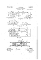
Fig. 1 is a view ,in side elevation of a suction cleaner embodying my invention;
Fig. 2 is an enlarged fragmentary view in vertical longitudinal section, showing the improved switch-mounting means embodying my invention;
Fig. 3 is a left-hand end elevation of one of the component parts of the switch-mounting means which is shown in top plan view in Fig. 6;
Fig. 4 is a left-hand end elevational view of the other component part which is shown in top plan view in Fig. '7;
Fig. 5 is an enlarged sectional view taken on line V-V of Fig. 2, certain parts being omitted for clarity of illustration;
Fig. 6 is a section taken on line VI-VI of Fig. 2;
Fig. 7 is a top plan view of the part shown in Fig. 3;
means and said handle are assembled and secured Fig. 8 is a top plan view of the part shown in Fig. 4;
Fig. 9 is an enlarged, front elevational view looking in the direction of the line IXIX on Fig. 6; and V Fig. 10 is a view similar to Fig. 2, showing a modified form of construction.
Referring to Fig. 1, there is shown a tank type cleaner [0 supported on runners II and provided with a handle I2 extending longitudinally of, and in parallel spaced relation to, the top of the cleaner. The cleaner I 6 includes a cylindrical, elongated body portion l3 and an end bell l4 detachably secured to the body portion i3 and forming one end of the cleaner casing. The end bell I4 is provided with a coupling member to which a hose I may be connected in the usual way. The other end of the hose I5 is provided with a suitable nozzle or dusting tool (not shown). The other end of the body portion I3 is tapered and provided with an exhaust opening IS. within the cleaner casing there is mounted the usual motor I1 which drives a fan (not shown) for drawing dirt-laden air through the hose I5 into and through afilter bag, which is also not shown. The filtered air is discharged through the exhaust opening Hi.
The motor I! is connected to a switch I8 by wires I9 passing through an opening in the top of the casing. Electrical energy is supplied to the motor 11 by an electric cord 2I, provided with a protective sleeve 22 having an enlarged head 23. The cord 2| is connected to the switch I 8 in any approved manner. As shown in Fig. 2, the switch 18 is located wholly outside of the cleaner casing and is supported in position by the improved mounting means embodying'myinvention.
Theimproved switch-mounting means includes a mounting block 24 and a closure or cover member 26, which are shown in left-hand end elevation in Figs. 3 and 4 and in top plan view in Figs. 7 and 8; V The mounting block 24 is formed of a vertical side wall 28 and enlarged end bosses 3i] and 32. The vertical wall 28 and the bosses 30 and 32 form a pocket or recess for accommodating the switch l8. The- end bosses 30 and 32 are provided with vertical bores 34 for receiving bolts 36," carried by the handle I4; and adapted to pass through suitable openings in the top of the cleaner. The bolts 36 are adapted to be engaged by retaining nuts 38 disposed within the cleaner casing. The block 24 is also provided with a horizontal groove 'iormed in the wall 28 and inthe juxtaposed faces of the end bosses 30 and 32. The groove 40 is formed at a point substantially halfway between the top and bottom of the mounting block 24, as shown in Figs. 2 and 5.
The end boss 32 of the mounting block 24 is further provided with a horizontal recess including a portion 44 and a portion 46 which are adapted to accommodate corresponding interfitting projections or bosses on the juxtaposed face of the closure member 26 when the switchmounting means is assembled. The recesses 44 and 46 terminate in an inner arcuate wall which forms a seat for the electric cord and its protective'sleeve. 'The seat referred'to includes a portion 50 for accommodating the body of the sleeve 22, a portion 52 for accommodating the enlarged head 23 of the sleeve, and a portion 54 for accommodating the cord 2!. of the recess is provided with spaced arcuate'beads 56 which are adapted to coact with corresponding beads on the closure member 26 to compress thesheathing of the electric cord to provide strain relief. The end boss 38 of the. mounting block 24 is provided with a recess 48, also adapted to receive a corresponding projection on. th juxtaposed side of the closure member 26.
The closure member 26 includes a vertical. side wall 58 whichis recessed toform a horizontal shelf or shoulder 60, coextensive and in horizontal alignment with the groove 40 in the block 24. The closure member 25 includes bosses 62, 64 and ES, which when the mounting meansis assembled, enter recesses '44, 45 and'48'with the shoulder 65 and the boss 65 abutting'against the'vertical surfaces Stand 69' of the bosses 30- and 321 The The portion. 54
The lower portions of the side walls 28 and 58 r are recessed to form oppositely-disposed grooves 15 and i8, and are provided with humps or projections 8!} and 82 which begin at a point below the groove 49 in the wall 28 and shelf Bil in the wall 58 and terminate just above the grooves Hi and I3, as clearly shown in Fig. 5. i
The switch assembly I8 and the switch-operating button as are carried by a plate 92'. The switch-operating button is provided with an inverted cup-shaped cover I52 which extends upwardly through an opening I04, formed in the handle I2, and is provided with an enlarged lower rim IBE. The enlarged lower riin HIE prevents the cover I82 from being withdrawn throughthe opening Ind, and bears against the adjacent side of the boss 35 and the adjacent side of a guard I38 carried by the wall 28 of the block 24, to guide the button 90 in its vertical movement in turning the switch on or off? In order to make afluidtight connection between the wires I9 and the opening 20in the top wall of the casing, the wires I9 are passed through relatively tight apertures formed in a grommet 96, which may be of rubber or the like and which has a flange I98 engaging the upper rim of the opening 20:
Assembly In assembling a cleaner provided with a switch mounting embodying this invention, the switch ,plate 92, carrying the switch I8 and the switch operating button 99, is inserted along three sides thereof into the groove 4|! in the back wall 28 and in the juxtaposed sides of the bosses 30 and 32 of the mounting block 24. The cover I02 is then placed on the switch button 90 and the block 24, carrying the parts thus far described, is placed on top-of the cleaner casing. The handle I2 is then placedron top of the block 24 with .the bolts 3t thereof. extending through the bores throughthe'apertures in the grommetfor connection to the terminals of the switch I8. The grommet. 95' is now inserted into the Opening 23 and the portion of the flange: I05 Offthfl grommetadjacent' the wall 28; is forced into thegroove I8 and between the lower portion of the hump Bil and the top of the. cleaner casing. Thi 'insures a tight joint between that portion ofthe flange of the grommet and the top of the casing. Thev electric cordZI and'its' protecting sleeve: 22 are positioned'in the recesses 50 and54, with-the enlarged head 23 of the protecting sleeve 22 seated in the recess52 as clearly shown in Fig. 2. The wires l9 and the terminals of the cord 2! are connected to the terminals of the switch in the usual'way. To complete the assembly,- the Closure member 25 is placed on top of the cleaner in contiguous juxtaposition to the mounting block 25 and is clamped thereto by the screws 70. With the closure member '26 clamped to the mounting block 24, the portion of the flange IEO adjacent the wall 53 of the closure member engages the recess l8 and is squeezed between the lower portion of the hump 32 and the top of the casing to insure a tight joint between that portion of the flange and the top of the casing.
Also, with the mounting block 2 and the closure 26 clamped tightly together, the beads 55 and, coact to pinch the sheathing of the electric cord 2!, thus tightly clamping the same and providing strain relief for the terminal connections of the cord.
The fourth side of the switch plate 92 or the side thereof adjacent the closure member 2 5 is, as shown in Fig. 5, supported on the ledge or shelf 66 formed in the wall 58 of the closure member 25.
In Fig. 9, there is shown a modified form of construction which is identical With that shown in the preceding figures, exceptthat the switch plate 92, the groove 4-8 and the shelf Bil are omitted. In this construction, the switch [8 is provided With a threaded portion H5 adapted to engage a threaded opening H8 in the handle l2 and is retained in position by a nut I26. Except for this difierence, the structure is exactly as that shown in Figs. 1 to 8 and is, therefore, not shown or described in detail.
It will thus be seen that by my construction, the switch and all of its connections are mounted exteriorly of the cleaner casing and that the same are accessible for inspection and servicing upon disengagement of the closure member 2-6 from the mounting block 2 3. It will also be seen that the opening 29 is adequately and easily sealed by the rommet 93, the body portion of which fits tightly in the opening 28 and the flange of which is tightly clamped between the hump portions 8d and 82 and the top of the casing.
While I have shown forms, it will be obvious to those skilled in the art that it is not so limited, but is susceptible of various other changes and modifications without departing from the'spirit thereof, and I desire, therefore, that only such limitations shall be placed thereupon as are specifically set forth in the appended claims.
What I claim is:
1. In a suction cleaner, a casing, a handle for said cleaner, a mounting block disposed between said casing and said handle and having a recess therein, means for securing said handle and said block to said casing, a switch for controlling the supply of electrical energy to said cleaner, said switch being mounted in said recess, there being an opening in the wall of said casing communicating with said recess and through which wires leading from the terminals of said switch are adapted to pass, an electric cord for supplying electrical energy to said switch, a closure member for closing said recess, and means for securing said closure member to said block, there being complementary recesses in the juxtaposed, contiguous walls of said mounting block and said closure member forming a bore through which m invention in several plate.
4. The structure recited in claim 1 together with means'for effecting a fluid-tight seal between the opening in the wall of the casing and said wires comprising a grommet including a body portion adapted to be inserted into said opening and having apertures therein through which said wires pass, and a flange engaging the upper rim of said opening, and means carried b juxtaposed portions of said block and said closure member which, when said block and said closure member are assembled, clamp portions of said flange against said wall of said casing.
5. In a suction cleaner, a casing, a handle extending above said casing, there being an opening in said handle, a switch for controlling the supply of electrical energy to said cleaner, an operating button for said switch movable through said opening, means for guiding and limiting movement of said operating button, and an electric cord for supplying electric energy through said motor to said switch, means for mounting said switch between said handle and the top of said casing whereby said switch and the connections of the terminals of said switch to the terminals of said cord are wholly disposed outside 'said casing, said means including interfitting complementary members, means carried by said handle and extending through one of said members and the wall of said casing for securing said handle and said member tothe top of said casing, means for supporting said switch between said members, there being an opening in the'top of said casing through which wires leading from the terminals of said switch are adapted to pass, means for closing said opening, and means for clamping said members together in assembled relation, there being complementary recesses formed in juxtaposed portions of said members which, when said members are assembled, provide a seat engaging a portion of said cord.
6. The combination with a suction cleaner including a casing, a handle, and a switch for controlling the supply of electrical energy to said cleaner, of means for mounting said switch between the handle and the casing with the switch and all of its terminals disposed wholly outside of said casing and with said means supporting at least a portion of said handle.
7. In a suction cleaner, a casing, a handle extending above said casing, mounting means for mounting a switch controlling the supply of electrical energy to said cleaner, said means including a block disposed between said casing and said handle and having a recess therein adapted to receive a switch, and a closure member for closing said recess, means for securing said handle and said block to said casing, means for mounting said switch in said recess, there being an opening in the wall of said casing communicating with said recess and through which wires leading from the terminals of said switch are adapted to pass, and means for securing said closure member to 's'aid' block, saidmountingmeans havingvanopen ing therethrough for receiving an. electric cord for connection to the. terminals of said switch.
8; The combination with a suction cleaner including a'casing', and a handlejo'flmeans for mounting a switch between said" casing and said handle, with the switch and all of its terminals disposed wholly outside of said casing and with said mounting means supportingxat least'a or 'tion'. of said handle, said mounting means inher for engaging a portion of an electric cord leading from a source of electrical energy to the terminals of said switch.
9. Means for mounting a switch on a support, said means including a block having end walls and an intermediate side wall, there being a recess intermediate said end walls for receiving a switch, said recess having top and bottom openlugs for passage of the switch pushbutton and the wires leading from the terminals of said switch, respectively, a closure for said recess, and means for securing said closure to said block, there being complementary recesses in said block and said closure member for passage of an electric cord leading to the terminals of said switch 10. The structure recited in claim 9 in which said block and said closure member are provided with shelves in juxtaposed walls thereof for supporting a plate carrying said switch.
CHARLES H. TAYLOR.
Priority Applications (1)
| Application Number | Priority Date | Filing Date | Title |
|---|---|---|---|
| US533522A US2394271A (en) | 1944-05-01 | 1944-05-01 | Suction cleaning apparatus |
Applications Claiming Priority (1)
| Application Number | Priority Date | Filing Date | Title |
|---|---|---|---|
| US533522A US2394271A (en) | 1944-05-01 | 1944-05-01 | Suction cleaning apparatus |
Publications (1)
| Publication Number | Publication Date |
|---|---|
| US2394271A true US2394271A (en) | 1946-02-05 |
Family
ID=24126321
Family Applications (1)
| Application Number | Title | Priority Date | Filing Date |
|---|---|---|---|
| US533522A Expired - Lifetime US2394271A (en) | 1944-05-01 | 1944-05-01 | Suction cleaning apparatus |
Country Status (1)
| Country | Link |
|---|---|
| US (1) | US2394271A (en) |
Cited By (8)
| Publication number | Priority date | Publication date | Assignee | Title |
|---|---|---|---|---|
| US2562268A (en) * | 1948-12-17 | 1951-07-31 | Philco Corp | Combined extension cord and handle forming means |
| US2573091A (en) * | 1946-03-29 | 1951-10-30 | Jr Charles Kepler Brown | Combined vacuum cleaner and tool casing |
| US2584883A (en) * | 1948-03-26 | 1952-02-05 | Eugene J Karsch | Accessory for automotive vehicles |
| US2684413A (en) * | 1951-11-24 | 1954-07-20 | Hoover Co | Electric switch |
| US3123792A (en) * | 1964-03-03 | Switch-rheostat | ||
| US3867591A (en) * | 1974-01-16 | 1975-02-18 | Whirlpool Co | One piece switch holder and foot operated hinge actuator for vacuum cleaner switch |
| US5413358A (en) * | 1993-01-12 | 1995-05-09 | A-Dec, Inc. | Seal for push-button switches |
| WO2020131559A1 (en) * | 2018-12-21 | 2020-06-25 | Tti (Macao Commercial Offshore) Limited | Floor cleaner |
-
1944
- 1944-05-01 US US533522A patent/US2394271A/en not_active Expired - Lifetime
Cited By (10)
| Publication number | Priority date | Publication date | Assignee | Title |
|---|---|---|---|---|
| US3123792A (en) * | 1964-03-03 | Switch-rheostat | ||
| US2573091A (en) * | 1946-03-29 | 1951-10-30 | Jr Charles Kepler Brown | Combined vacuum cleaner and tool casing |
| US2584883A (en) * | 1948-03-26 | 1952-02-05 | Eugene J Karsch | Accessory for automotive vehicles |
| US2562268A (en) * | 1948-12-17 | 1951-07-31 | Philco Corp | Combined extension cord and handle forming means |
| US2684413A (en) * | 1951-11-24 | 1954-07-20 | Hoover Co | Electric switch |
| US3867591A (en) * | 1974-01-16 | 1975-02-18 | Whirlpool Co | One piece switch holder and foot operated hinge actuator for vacuum cleaner switch |
| US5413358A (en) * | 1993-01-12 | 1995-05-09 | A-Dec, Inc. | Seal for push-button switches |
| WO2020131559A1 (en) * | 2018-12-21 | 2020-06-25 | Tti (Macao Commercial Offshore) Limited | Floor cleaner |
| US10986975B2 (en) | 2018-12-21 | 2021-04-27 | Techtronic Floor Care Technology Limited | Floor cleaner |
| US11690492B2 (en) | 2018-12-21 | 2023-07-04 | Techtronic Floor Care Technology Limited | Floor cleaner |
Similar Documents
| Publication | Publication Date | Title |
|---|---|---|
| US2394271A (en) | Suction cleaning apparatus | |
| US9608392B1 (en) | Arrangement for energized rail for movable sockets | |
| US2439182A (en) | Blower control device for suction cleaners | |
| US3273194A (en) | Vacuum cleaner | |
| US2377187A (en) | Electrical connector | |
| US2274971A (en) | Suction cleaner | |
| US1539068A (en) | Motor hand tool | |
| US2337987A (en) | Convertible radio cabinet | |
| US4522310A (en) | Housing holder and cooperating detachable housing | |
| US3549951A (en) | Meter-box with discharge side mounting arrangement | |
| US2093419A (en) | Automatic switch for vacuum cleaners | |
| US2455967A (en) | Electric heater | |
| US2017937A (en) | Suction cleaner | |
| US2537205A (en) | Suction cleaner | |
| US2176119A (en) | Vacuum cleaner | |
| US3029462A (en) | Vacuum cleaner and cord-reel construction | |
| US2272164A (en) | Strain relief and switch assembly | |
| JPH08126226A (en) | Uninterruptible power system | |
| US1735556A (en) | Handle and switch | |
| US2296446A (en) | Vacuum cleaner | |
| US2312426A (en) | Vacuum cleaner | |
| US1311376A (en) | Electric-conduit fitting | |
| US2455786A (en) | Handle for portable blowers | |
| US2171754A (en) | Dust disposal device for vacuum cleaners | |
| GB528546A (en) | Improvements in or relating to vacuum cleaners |