US2391663A - Steam spotting unit - Google Patents
Steam spotting unit Download PDFInfo
- Publication number
- US2391663A US2391663A US514084A US51408443A US2391663A US 2391663 A US2391663 A US 2391663A US 514084 A US514084 A US 514084A US 51408443 A US51408443 A US 51408443A US 2391663 A US2391663 A US 2391663A
- Authority
- US
- United States
- Prior art keywords
- steam
- valve
- water
- outlet
- chamber
- Prior art date
- Legal status (The legal status is an assumption and is not a legal conclusion. Google has not performed a legal analysis and makes no representation as to the accuracy of the status listed.)
- Expired - Lifetime
Links
- XLYOFNOQVPJJNP-UHFFFAOYSA-N water Substances O XLYOFNOQVPJJNP-UHFFFAOYSA-N 0.000 description 37
- 238000004140 cleaning Methods 0.000 description 7
- 239000004744 fabric Substances 0.000 description 7
- 210000002445 nipple Anatomy 0.000 description 3
- 238000010276 construction Methods 0.000 description 2
- 239000012530 fluid Substances 0.000 description 2
- 239000000203 mixture Substances 0.000 description 2
- 230000006978 adaptation Effects 0.000 description 1
- 230000004075 alteration Effects 0.000 description 1
- 230000001419 dependent effect Effects 0.000 description 1
- 238000009413 insulation Methods 0.000 description 1
- 230000014759 maintenance of location Effects 0.000 description 1
Images
Classifications
-
- D—TEXTILES; PAPER
- D06—TREATMENT OF TEXTILES OR THE LIKE; LAUNDERING; FLEXIBLE MATERIALS NOT OTHERWISE PROVIDED FOR
- D06F—LAUNDERING, DRYING, IRONING, PRESSING OR FOLDING TEXTILE ARTICLES
- D06F43/00—Dry-cleaning apparatus or methods using volatile solvents
- D06F43/002—Spotting apparatus
Definitions
- Our invention relates to apparatus for supplying steam of varying degrees of dryness or wetness for use in steam spotting apparatus use ful to tailors and cleaners for removing spots from fabrics.
- Our invention is not limited to this particular use, and there are other uses and adaptations within the scope of the invention as dened in the appended claims.
- One object of our invention is to provide apparatus under the control of the operator capable of producing dry or wet steam as desired for use in cleaning fabrics and in which the degree of wetness may be varied at will and as required by the operator.
- Another object of our invention is to provide apparatus of the general character referred to above which is 'of a simple, sturdy, and economical construction employing but a single outlet, a single valve, and a single proportioning means 'whereby the amount of water added to the steam to determine its wetness may be determined by the operator.
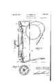
- Fig. 1 is an elevational view partly in section showing a device incorporating the features of invention.
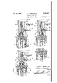
- Fig. 2 is an enlarged fragmentary sectional view showing the valve yand proportioning means of our invention with thevalve in closed position.
- Fig. 3 is a similar view showing the valve open but showing steam being supplied to the outlet.
- Fig. 4y is a fragmentary sectional view showing the structure with the proportioning means in such a position that the steam is being throttled and an amount of water, as well as steam, is being delivered to the outlet.
- Fig. 5 is a view corresponding to the other views but showing the steam completely shut off and only water being supplied to the outlet.
- Fig. 6 is a sectional view taken on the line 6-6 of Fig. 5.
- a chamber II containing steam in its upper end and water at its lower end, the steam being supplied by a steam admission means such as a pipe I2.
- the water is preferably formed by the steam condensing in the chamber II.
- the upper end of the chamber II has a threaded opening I 6 which threadedly supports a housing comprising an upper piece I 'I and a lower piece I8 threadedly vsecured together.
- the lower end of the lower piece extends downwardly into the chamber I I in the form of a nipple I9 and has a downwardly extending pipe 20 secured thereto which extends to the part of the chamber containing the water and constitutes a water supply passage.
- Steam supply passage or passages 22 are formed in the nipple I9 which communicate with the upper part of the chamber II which contains the steam. In this manner both the steam part and the water part of the chamber are connected to the outlet 23.
- This outlet 23 is in communication with the flexible hose 24, on the end of which a spotting device 25 is attached.
- a Valve including a body 21 and a valve disc 28 adapted to engage a valve seat 29 provided in the upper end of the enlargement 30 of the outlet which comprises a valve chamber.
- a Valve rod 32 Extending upwardly from the valve is a Valve rod 32, the upper end of which is provided with a nut spring retainer 33 which compresses a spring 34 against a stulng box assembly 35, thus accomplishing two things: iirst, a yieldable retention of the valve in closed position; and, second, a. yieldable application of pressure to the stuiiing box assembly, thusforming a fluid-tight seal.
- an operating lever 31 which is pivoted on a pivot support arm 38 and extends horizontally above the nut 33 and is engaged at its free end by a depending link 39 operatively connected to a foot pedal 40.
- the foot pedal 40 is pivoted to a base 4
- a proportioningI device that is connected to the valve to move in unison therewith.
- a stem 45 which has a proportioning means or a proportioning device at its lower end.
- This proportioning device is provided i'n the form of a piston element 46 mounted on the. stem 45, which has a slidable contact with a cylinder bore 41 provided by the nipple I9 of the lower housing piece I8. 'Ihis cylindrical; bore 41.' mayv be con-- ⁇ sidered as constituting a part of the outlet.
- Water supply passage is at al1 times connected' to the outlet above the proportioning means 46; and this communication i'sv conveniently provided for by axialopenings 50v formedthrough the piston element 46..
- toT do is' to further'depress: the foot. pedal 40' so as. tc:A move; the partsinto: the position shown in Fig; 5; whereinl the piston 46 completely closes the. steam. supply.V passages 22,. thus preventing any steam' from. dowing through. the outlet and thus utilizing the. pressurey in the chamber to cause Water exclusively' to fl'ow' through ⁇ the. outlet, the hose, and tothe nozzle. for-use..
- our device has. but; a single'. control and thereforel eliminates the necessity ofy operating two'V separate valves or. contrai means, one. for the water and the other for the steam.
- the different parts are set in the properly adjusted position and will remain in adjustment during the life of the device.
- the apparatus of our invention is a marked advantage over prior art devices having separate controls or having separate valves and by virtue of its simplicity is easy to operate, of sturdy construction, and of long life.
- an apparatus. for supplying dry or wet steam for treating or' cleaning fabrics they combination of: a. chamber containing water in its lower parti andsteam in. its upper part; admission means for admitting steam to said chamber; uid outlet conduit forsaid chamber; a. valve forl controlling the flow of. liuid through said outlet conduit; a water supplyv passage from. the lower part ofsaidv chamber to said outlet conduit int'eriorly ⁇ of said valve; a steam supply passage from the upper' part of said chamber to said outlet conduit interiorly of said valve;v and steam supply passage: throttling means in said outlet conduit below said valve and so connected to said valve that after said valve is opened and steam is flowing through said outlet conduit a. further opening of the valve.
- av chamber containing Water in its lower end and steam in its upper end; an outlet for said chamber; a valve for opening or closing saidv outlet; a tube extending from said outlet interiorly of said valve to the lower end of said chamber; a steam supply passage in the Wall of said tube connecting the interior of the tube with the upper end of said chamber; operating means for operating said valve; and steam supply passage throttling means operatively connected t0 said valve and slidable in said tube, said throttling meansl having an opening therethrough for passage of Water and being so positioned that, after 'actuation of said valve operating means to open said valve, further movement of said valve operating means causes said throttling means to throttle said steam supply passage whereby steam pressure in the upper end of said chamber will force Water upwardly through said tube to said outlet.
- a chamber containing water in one portion and steam in another communieating portion a fluid outlet conduit; a water supply passage connecting the water portion of said chamber to said outlet conduit; a steam supply passage from the steam portion of said chamber to said outlet conduit; a valve positioned in said outlet conduit beyond the points of entry of said water and steam supply passages and arranged to control discharge of fluid from said outlet conduit; an operating means for operating said valve; and a steam supply passage throttlingr device so operatively connected to said valve and so arranged that after said operating means has been actuated to open said valve and steam is flowing through said outlet a further movement of said operating means in the direction which opened said valve will cause said throttling means to throttle said steam supply passage, the extent of such throttling being dependent on the extent of said further movement of said operating means.
Landscapes
- Engineering & Computer Science (AREA)
- Textile Engineering (AREA)
- Cleaning By Liquid Or Steam (AREA)
Description
ec. 25, 1945. A. J. WEBER ET Al. 2,391,653
STEAM SPOTTING UNI'T Filed Dec. 13, 1943 2 Sheets-Sheet l EAM/57 (MQ/5am, Brwentorg;
Patented Dec. 25, 1945 UNrrED STATES PATENT' OFFICEv STEAM SPOTTING Albert J. Weber and Ernest L. Chrisman, Los Angeles, Calif.
Application December 13, 1943, Serial No. 514,084
4 Claims.
Our invention relates to apparatus for supplying steam of varying degrees of dryness or wetness for use in steam spotting apparatus use ful to tailors and cleaners for removing spots from fabrics. Our invention, however, is not limited to this particular use, and there are other uses and adaptations within the scope of the invention as dened in the appended claims.
One object of our invention is to provide apparatus under the control of the operator capable of producing dry or wet steam as desired for use in cleaning fabrics and in which the degree of wetness may be varied at will and as required by the operator.
Another object of our invention is to provide apparatus of the general character referred to above which is 'of a simple, sturdy, and economical construction employing but a single outlet, a single valve, and a single proportioning means 'whereby the amount of water added to the steam to determine its wetness may be determined by the operator.
It is also an object of our invention to provide apparatus of the character referred to in which there is a proportioning means which determines the amount of water which is added to the steam in order to control its wetness, this proportioning means being directly associated with the closure valve for the steam and water chamber of the device and movable therewith simultaneously with the movement of the outlet valve, which outlet valve is under the control of the operator.
It is another object of our invention to provide an apparatus for supplying dry or wet steam for treating or cleaning fabrics in which there is a proportioning means which is so positioned that when the closure valve for the steam and water containing chamber is rst opened steam is allowed to pass through the outlet, and in which further opening movement of the valve causes the steam to be throttled which develops pressure and causes water to be forced into the outlet so that it will mix with the steam, thus producing steam of the desired wetness.
Other objects and advantages of our invention will be brought out during the course of the following detailed description of one form of our invention which has proven to be quite satisfactory for its intended use.
Referring to the drawings in detail,
Fig. 1 is an elevational view partly in section showing a device incorporating the features of invention.
Fig. 2 is an enlarged fragmentary sectional view showing the valve yand proportioning means of our invention with thevalve in closed position.
Fig. 3 is a similar view showing the valve open but showing steam being supplied to the outlet.
Fig. 4y is a fragmentary sectional view showing the structure with the proportioning means in such a position that the steam is being throttled and an amount of water, as well as steam, is being delivered to the outlet.
Fig. 5 is a view corresponding to the other views but showing the steam completely shut off and only water being supplied to the outlet.
Fig. 6 is a sectional view taken on the line 6-6 of Fig. 5.
Referring to the drawings and particularly Fig. 1, there is a chamber II containing steam in its upper end and water at its lower end, the steam being supplied by a steam admission means such as a pipe I2. The water is preferably formed by the steam condensing in the chamber II. For
insulation purposes,'we provide'a shell I4 and in addition to this the necessary drainage and cleaning outlets, such as indicated at I5, are provided'.
vReferring to Figs. 2 to 6, the upper end of the chamber II has a threaded opening I 6 which threadedly supports a housing comprising an upper piece I 'I and a lower piece I8 threadedly vsecured together. The lower end of the lower piece extends downwardly into the chamber I I in the form of a nipple I9 and has a downwardly extending pipe 20 secured thereto which extends to the part of the chamber containing the water and constitutes a water supply passage. Steam supply passage or passages 22 are formed in the nipple I9 which communicate with the upper part of the chamber II which contains the steam. In this manner both the steam part and the water part of the chamber are connected to the outlet 23. This outlet 23 is in communication with the flexible hose 24, on the end of which a spotting device 25 is attached.
i For the purpose of closing the outlet 23, we provide a Valve including a body 21 and a valve disc 28 adapted to engage a valve seat 29 provided in the upper end of the enlargement 30 of the outlet which comprises a valve chamber. Extending upwardly from the valve is a Valve rod 32, the upper end of which is provided with a nut spring retainer 33 which compresses a spring 34 against a stulng box assembly 35, thus accomplishing two things: iirst, a yieldable retention of the valve in closed position; and, second, a. yieldable application of pressure to the stuiiing box assembly, thusforming a fluid-tight seal.
For operating the valve, We provide an operating lever 31 which is pivoted on a pivot support arm 38 and extends horizontally above the nut 33 and is engaged at its free end by a depending link 39 operatively connected to a foot pedal 40. The foot pedal 40 is pivoted to a base 4| of the apparatus and is in a convenient position to be actuated by the foot of the operator.
We prefer to provide a proportioningI device that is connected to the valve to move in unison therewith. In the present instance, from the valve body 21 is a stem 45 which has a proportioning means or a proportioning device at its lower end. This proportioning device is provided i'n the form of a piston element 46 mounted on the. stem 45, which has a slidable contact with a cylinder bore 41 provided by the nipple I9 of the lower housing piece I8. 'Ihis cylindrical; bore 41.' mayv be con--` sidered as constituting a part of the outlet. The.
Water supply passage is at al1 times connected' to the outlet above the proportioning means 46; and this communication i'sv conveniently provided for by axialopenings 50v formedthrough the piston element 46..
As shown in Fig. 2 when the. valve. closes the outlet the proportioning means ispositioned above the. steam supply passages'. 22,. and therefore. at this time both ends of the. chamber ll are in communication with the outlet andy thev water c supply' passage will be 'lled'. with steam. down to. the. water level in, the chamber.
The operation of our device is' briey'explai'ned as follows.. When the operator is in need of steam. he may need dry steam or wet steam, or l. in instances, he mayl require. hot water.. This, of
course,` dependsv upon the fabric: which he is cleaning or' spotting; and; the nature of the suhstance which must: be removed. When. the operator is in need of steam or water, he depresses the pedall 40v which opens. the valve and moves the partsv into, the position shown in Fig; 3'. At this time; theV valve. i's open and the steam supply passages 22 are also. open- Therefore, steam will pass through the openings 50 in the piston 4.1i` and through thev outlet 23, the hose. 24l and the spotting device 2'5. Dry steam therefore isJ supplied to the spotting device.. Should the operator de'- sire steam of more-wetness, all he has. to do is to depress: the pedal 4ui a. greater. distance sov that the piston 46,` will move into a. position as shown in Fig. 4-I where the steam. supply passages are partly closed. This throttles the steam supply passages, cutting down the ilow'of'steam, building up the necessary pressure against the water in the lower end of the chamber, and causing'water to flow upward. through the water supply passage formed by the pipev 20 and into. the outlet, the` water mixing with. the steamy. and forming steam of the desired wetness.. Itwill be seen that the position; of. the proportioning means: or, more specifically, the piston. 46,` determines the amount of steam which will ow through the; outlet. If the operator desires water exclusively.;y all he. is required? toT do is' to further'depress: the foot. pedal 40' so as. tc:A move; the partsinto: the position shown in Fig; 5; whereinl the piston 46 completely closes the. steam. supply.V passages 22,. thus preventing any steam' from. dowing through. the outlet and thus utilizing the. pressurey in the chamber to cause Water exclusively' to fl'ow' through` the. outlet, the hose, and tothe nozzle. for-use..
From the. foregoing description', it Willi be seen that our device has. but; a single'. control and thereforel eliminates the necessity ofy operating two'V separate valves or. contrai means, one. for the water and the other for the steam. The different parts are set in the properly adjusted position and will remain in adjustment during the life of the device. The apparatus of our invention is a marked advantage over prior art devices having separate controls or having separate valves and by virtue of its simplicity is easy to operate, of sturdy construction, and of long life.
Although we have disclosed herein but one form of our invention, it will be obvious to those skilled in the art that various modiiications and alterations may be made without departing from the spiritfand scope of our invention as defined in the statement of invention and appended claims.
We claim as our invention:
1f.. In an apparatus for supplying dry or wet steam for treating or cleaning fabrics, the combinatiorr of a chamber containing water at its lower part and steam at its-upper part; an outlet conduit extending. downwardly through said chamber to its lower part; steam supply passage means connecting said outlet conduit to the upper part of. said chamber; a. valve for closing said outlet conduit; an operatingy means for operating said. valve; and steam passage throttling means soconnected. to said valve that. after said valve has been opened and steam isv flowing through said outlet conduit. further movement of said valve operating means in the. direction that opened the. valve.- will. cause said throttling means: to. close said steam supply passage means, thus causing water to flow through said outlet conduit, a partial closing of. said'v steam supply passageA meansA causing a. mixture of steam and Waterv to ow from said. outlet conduit.
2., In; an apparatus. for supplying dry or wet steam for treating or' cleaning fabrics, they combination of: a. chamber containing water in its lower parti andsteam in. its upper part; admission means for admitting steam to said chamber; uid outlet conduit forsaid chamber; a. valve forl controlling the flow of. liuid through said outlet conduit; a water supplyv passage from. the lower part ofsaidv chamber to said outlet conduit int'eriorly` of said valve; a steam supply passage from the upper' part of said chamber to said outlet conduit interiorly of said valve;v and steam supply passage: throttling means in said outlet conduit below said valve and so connected to said valve that after said valve is opened and steam is flowing through said outlet conduit a. further opening of the valve. causes said steam supply passage throttling means to throttle said steam supply passage thereby` causing steam entering said admission means to accumulate in said charnber to cause- Water to be forced up through said water supply passage. into` said outlet conduit in amounts dependingl on the extentv of throttling of said' steam supply passage.
3. In an apparatus for supplying dry or wet steam for treatingY or cleaning fabrics', the combination of: av chamber containing Water in its lower end and steam in its upper end; an outlet for said chamber; a valve for opening or closing saidv outlet; a tube extending from said outlet interiorly of said valve to the lower end of said chamber; a steam supply passage in the Wall of said tube connecting the interior of the tube with the upper end of said chamber; operating means for operating said valve; and steam supply passage throttling means operatively connected t0 said valve and slidable in said tube, said throttling meansl having an opening therethrough for passage of Water and being so positioned that, after 'actuation of said valve operating means to open said valve, further movement of said valve operating means causes said throttling means to throttle said steam supply passage whereby steam pressure in the upper end of said chamber will force Water upwardly through said tube to said outlet.
4. In an apparatus for supplying dry or wet steam, the combination of: a chamber containing water in one portion and steam in another communieating portion; a fluid outlet conduit; a water supply passage connecting the water portion of said chamber to said outlet conduit; a steam supply passage from the steam portion of said chamber to said outlet conduit; a valve positioned in said outlet conduit beyond the points of entry of said water and steam supply passages and arranged to control discharge of fluid from said outlet conduit; an operating means for operating said valve; and a steam supply passage throttlingr device so operatively connected to said valve and so arranged that after said operating means has been actuated to open said valve and steam is flowing through said outlet a further movement of said operating means in the direction which opened said valve will cause said throttling means to throttle said steam supply passage, the extent of such throttling being dependent on the extent of said further movement of said operating means.
ALBERT J. WEBER.
ERNEST L. CHRISMAN.
Priority Applications (1)
| Application Number | Priority Date | Filing Date | Title |
|---|---|---|---|
| US514084A US2391663A (en) | 1943-12-13 | 1943-12-13 | Steam spotting unit |
Applications Claiming Priority (1)
| Application Number | Priority Date | Filing Date | Title |
|---|---|---|---|
| US514084A US2391663A (en) | 1943-12-13 | 1943-12-13 | Steam spotting unit |
Publications (1)
| Publication Number | Publication Date |
|---|---|
| US2391663A true US2391663A (en) | 1945-12-25 |
Family
ID=24045723
Family Applications (1)
| Application Number | Title | Priority Date | Filing Date |
|---|---|---|---|
| US514084A Expired - Lifetime US2391663A (en) | 1943-12-13 | 1943-12-13 | Steam spotting unit |
Country Status (1)
| Country | Link |
|---|---|
| US (1) | US2391663A (en) |
Cited By (7)
| Publication number | Priority date | Publication date | Assignee | Title |
|---|---|---|---|---|
| US2445592A (en) * | 1946-02-01 | 1948-07-20 | Braun Inc G A | Garment spotting apparatus |
| US2598447A (en) * | 1948-12-31 | 1952-05-27 | David A Freeman Corp | Steam hydrator |
| US2598571A (en) * | 1947-06-13 | 1952-05-27 | Longmuir James | Dry cleaning apparatus |
| US2651511A (en) * | 1951-04-20 | 1953-09-08 | Bill Glover Inc | Device for tempering steam |
| US2670621A (en) * | 1950-03-18 | 1954-03-02 | Bill Glover Inc | Garment spotting machine |
| US2723840A (en) * | 1952-07-29 | 1955-11-15 | G H Bishop Company | Steam hydrator |
| US4071586A (en) * | 1976-10-26 | 1978-01-31 | Copes-Vulcan, Inc. | Variable orifice desuperheater |
-
1943
- 1943-12-13 US US514084A patent/US2391663A/en not_active Expired - Lifetime
Cited By (7)
| Publication number | Priority date | Publication date | Assignee | Title |
|---|---|---|---|---|
| US2445592A (en) * | 1946-02-01 | 1948-07-20 | Braun Inc G A | Garment spotting apparatus |
| US2598571A (en) * | 1947-06-13 | 1952-05-27 | Longmuir James | Dry cleaning apparatus |
| US2598447A (en) * | 1948-12-31 | 1952-05-27 | David A Freeman Corp | Steam hydrator |
| US2670621A (en) * | 1950-03-18 | 1954-03-02 | Bill Glover Inc | Garment spotting machine |
| US2651511A (en) * | 1951-04-20 | 1953-09-08 | Bill Glover Inc | Device for tempering steam |
| US2723840A (en) * | 1952-07-29 | 1955-11-15 | G H Bishop Company | Steam hydrator |
| US4071586A (en) * | 1976-10-26 | 1978-01-31 | Copes-Vulcan, Inc. | Variable orifice desuperheater |
Similar Documents
| Publication | Publication Date | Title |
|---|---|---|
| US2380956A (en) | Throwover regulator | |
| US2391663A (en) | Steam spotting unit | |
| US2578102A (en) | Antisurge mechanism for fluid spray apparatus | |
| US2402280A (en) | Fluid distributing system | |
| US1962214A (en) | Hot water temperature regulator | |
| US1809567A (en) | Transfer valve | |
| US2455754A (en) | Device for tempering steam | |
| US928732A (en) | Regulating-valve. | |
| US2219830A (en) | Spotting unit | |
| US2977989A (en) | Mixing valves for controlling the mixing of hot and cold fluids | |
| US2346821A (en) | Apparatus for spotting fabric materials | |
| US2045308A (en) | Mixing valve | |
| US2245934A (en) | Water supply control for wash | |
| US2635621A (en) | Frostproof hydrant | |
| US1873623A (en) | Valve | |
| US1530104A (en) | Combination faucet | |
| US2039570A (en) | Pump | |
| US1488206A (en) | Actuating mechanism | |
| US1842500A (en) | Vacuum valve ejector | |
| US2114999A (en) | Pressure treating apparatus | |
| US2651511A (en) | Device for tempering steam | |
| US881548A (en) | Air-exhausting liquid-supply apparatus. | |
| US594070A (en) | Antifreezing-valve | |
| US408418A (en) | Self-closing stop-cock | |
| US1689249A (en) | Steam and liquid control mechanism |