US2385196A - Pickup truck - Google Patents
Pickup truck Download PDFInfo
- Publication number
- US2385196A US2385196A US524749A US52474944A US2385196A US 2385196 A US2385196 A US 2385196A US 524749 A US524749 A US 524749A US 52474944 A US52474944 A US 52474944A US 2385196 A US2385196 A US 2385196A
- Authority
- US
- United States
- Prior art keywords
- chassis
- truck
- trailer
- bars
- side bars
- Prior art date
- Legal status (The legal status is an assumption and is not a legal conclusion. Google has not performed a legal analysis and makes no representation as to the accuracy of the status listed.)
- Expired - Lifetime
Links
Images


Classifications
-
- B—PERFORMING OPERATIONS; TRANSPORTING
- B62—LAND VEHICLES FOR TRAVELLING OTHERWISE THAN ON RAILS
- B62D—MOTOR VEHICLES; TRAILERS
- B62D63/00—Motor vehicles or trailers not otherwise provided for
- B62D63/06—Trailers
- B62D63/062—Trailers with one axle or two wheels
- B62D63/065—Trailers with one axle or two wheels forming an extension of the towing vehicle, i.e. with two point fixation
Definitions
- This invention appertains to trucks generally, and more particularly to a semi trailer pickup type thereof.
- An object of the invention is to provide a light-weight trailer truck that is adapted to be coupled to the so-called pickup" type of automotive vehicle; in order to permit of the hauling of loads in greatly increased volume, particularly on farms where loads are, more often thannot, of great bulk but light in weight,
- 'A'further object of the invention lies in the provision of a novel and simple hitch for coupling the trailer to a pickup truck, the hitch being adapted to couple the trailer to the frame of the truck, being adapted to permit the free movement of the trailer with relation" to the truck about a horizontal axis extending transversely of the truck and trailer, beingadapted to hold the trailer against movement in any other direction with relation to the truck, and being adapted to provide for the fullcontrol of the trailer from the pickup truck while moving forwardly or backing.
- Another object of the invention has to do with the provision of a trailer truck of the kind specified, which involves certain refinements in con-' struction that make for inexpensive manufacture, without sacrifice in durability and strength,
- a further objection of the invention lies in the provision of a novel form of chassis and an equally novel spring mounting of a large capacity body thereon, whereby the pulling strain through the coupling from the automotive vehicle is taken wholly by the chassis, such as would otherwise subject the body to destructive stresses, causing a shortening of its life'of usefulness.
- Figure 1 is a side elevation of the trailer pickup truck, in'accordance with the invention.
- Figure 2 is a top plan view.
- Figure 3 is a top plan view of'the chassis, with the body removed therefrom, and showing the coupling between the opposed ends of the chassis and the automotive vehicle.
- Figure 4 is a front end elevation of the chassis per se.
- Figure 5 is avertical-longitudinal section, taken through the line 5--5 of Figure 2.
- Figure 6 is a fragmentary view of opposed end portions'of the transverse coupling bars of the automotive vehicle and the chassis of the trailer pick up truck, and showing the coupling means therefor.
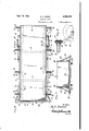
- Figure 7 is a vertical transverse section of the body'and body frame only,'the same being taken through the line 'l-"l of Figure 2.
- Figure 3 is a view similar to that of Figure 7, but showing a modified'body construction.
- the invention as it is exemplified therein, is generally comprised in a chassis? means for detachably coupling the chassis to the rear of an automotive vehicle, such'as' a pickup" truck; and a body on the chassis, with a loading capacity considerably greater than that of the loading compartment of the pickup'truck;
- the chassis is comprised in a frame, made up of longitudinal "side bars ll, preferably in the form of lengths'of light-weight, steel, U-channel beams; which have their front ends angularly benttd provide upstanding portions l2 and their rear ends upwardly and rearwardly curved, as at 13, to provide horizontally disposed extremities M," that lie in" a common plane with a transverse, draft, coupling'bar i5, connected to the upper ends of the vertical portions l2.
- a transverse bar I! connects the side bars H, at points centrally between the vertical portions l2 and'the'upwardly curved portions 13, and another transverse bar l8 connects the side bars ll, inwardly of the free ends of the horizontal portions I4.
- the free ends of the portions l4 carry vertically disposed bearing sleeves lil, in each of which is journalled the spindle 20 of a crazy" ground wheel or caster 23, the'spindle 20 projecting upwardly from the connected end of a fork or'yoke 2
- the coupling means includes thefront transverse bar l5, of the chassis, and alike bar 24 is to be secured to the frame beneath the rear end of the loading compartment A ( Figure 3), of the automotive pickuptruck, both of bars have their opposed vertical sides pro vided with a series of equidistantly spaced aper can have substantially free relative vertical move:
- the trailer pickup body is comprised in a bottom or bed 28 opposite side walls 29, and front and rear end walls 30 and 3
- the body or bed frame is supported above the chassis by a pair of springs 36, preferably of the half-elliptic leaf type, which are secured at their centers, as at 37, to the under sides of the cross bar ll, of the chassis, and have their ends pivoted, as at 38, to shackles 39, that are, in turn, pivoted, as at 40, to the longitudinal bars or beams 33; the shackle connections permitting endwise movements of the springs as they flatten under load.
- springs 36 preferably of the half-elliptic leaf type
- the body may be modified by having its side walls 29 provided with angled wings 4
- which are co-extensive with the top edges thereof, and extend outwardly of the same on supporting brackets 42 't'hatare secured to the side walls and braced, as at 43, therefrom
- the eyes 26 may be welded to thefacing sides of the bars and 20, and'the' bars may be arranged with their opensides facing forwardly and .rearwardly respectively, or facing downwardly.
- the bar 24 may befwelded, bolted or secured to the frame'ef the pickuptruckin any other suitable manner.
- These parts and the rods 2-1 provide ahitch which connects the trailer to the truck in such manner as to prevent any movement of the trailer with relation to the truck except'about a horizontal axis extending transyers'ely of thetruckandftrailer and which also provides for the full control of the trailer from the truck while moving forwardly or backing.
- the hitch also permits the trailer to be readily and quickly coupled to or uncoupled from the truck.
- a trailer truck comprising a chassis made up of parallel side bars, cross bars connecting the side bars at points to either side of the trans- V verse centers thereof, ground wheels journalled in the rear ends of the side bars, a draft coupling bar connecting the front ends of the side bars, semi-elliptic leaf springs secured at their centers to the cross bar located forwardly of the transverse centers of the side bars, and a body supported on th springs with its front end disposed in the plane of the front end of the'chassis and its rear end extending beyond the ground Wheels, with the side bars having elevated end portions disposed in a common plane for the support of the body from the central portions intermediate the elevated end .portions, so that the body is disposed substantially in the plane of a loading compartment of an automative pickup truck to which the trailer truck is adapted to be coupled.
- a semi-trailer truck comprising a chassis made up of parallel side bars having upwardly ex-. tending end portions terminating'in a common plane, cross bars connecting the side bars at points inwardly from their ends, ground wheels journalled in the rear elevated ends of the side bars, a body, springs mounted on the chassis forwardly of its transverse center and supporting the body above the chassis, and a draft coupling bar extending transversely of the chassis and connecting the ends of the upstanding portions at the front end of the chassis.
- a semi-trailer'ftruck comprising a chassis made up of parallel side bars having upwardly extending'end portions terminating in a'common plane, cross bars connecting the side bars at points inwardly from their ends; ground wheels journalled in the rear elevated ends of the side bars, a body, springs mounted on the chassis forwardly of its transverse center and supporting the body'above the chassis, and a draft coupling bar extending trans'verselyof the chassisand connecting the ends of the upstanding portions at the front'endof'the chassis, with upwardly extending portions'atthe rear ends of the side bars having rearwardly directed horizontal extensions and the ground wheels in the form of casters hav-' ing the spindles at the connected ends of their forks journalled in the free ends of the horizontal extension.
- a semi-trailer truck comprising a chassis having elevated'end portions lying in a common plane to provide a" low-slung intermediate portion, a coupling bar secured transversely of the forward end of the chassis, crazy wheels having their forks pivoted to the rear end of the chassis, semi-elliptic springs mounted longitudinally of the chassis forwardly of the transverse center of the low-slung portion thereofja'body supported on the springs and overlying the elevated end portions of the chassis,'the rear end of the body projecting beyond the 'rear end'of'the chassis and the crazy wheels;
- a trailer truck comprising a chassis, made up of parallel side bars having their forward ends turned upwardly at right angles and connected by a draft bar, the rear ends of the side bars curved upwardly and terminating in a horizontal plane with the upwardly turned forward ends, ground wheels vertically journaled in the upper ends of the upwardly curved rear ends of the side bars, semi-elliptical leaf springs secured to the central lower portion of the side bars by a transverse bar, and a body mounted on the upper ends of said springs in a plane above the upwardly turned ends of the side bars.
Landscapes
- Engineering & Computer Science (AREA)
- Chemical & Material Sciences (AREA)
- Combustion & Propulsion (AREA)
- Transportation (AREA)
- Mechanical Engineering (AREA)
- Body Structure For Vehicles (AREA)
Description
Sept. 18, 1945. B. A. DIESEL 2,385,196
PICK-"UP TRUCK Filed March 2, 1944 I :s sneGtS-Sht 1 INVENTOR. B. A .17: esel way-Wye.
PICK-UP TRUCK File-d March 2, 1944 3 Sheets-Sheet 3 ATTORNEYS B. A. DIESEL PICK-UP TRUCK Sept. 18, 1945.
3 Sheets-Shet 2 Filed March 2, 1944 jNVENTOR. B. A .Zh'esel aw 956M164.
ArruRN EYS Patented Sept. 18, 1945 UNITED sr 'r s PATENT OFFICE Y PICKUP TRUCK" 7 Benjamin A. Diesel, Los Ang'eles, Calif. 7 7 Application March 2, 1944, Serial Nit-524,749
f ,5 Claims (01. 2809-334) This invention appertains to trucks generally, and more particularly to a semi trailer pickup type thereof.
An object of the invention 'is to provide a light-weight trailer truck that is adapted to be coupled to the so-called pickup" type of automotive vehicle; in order to permit of the hauling of loads in greatly increased volume, particularly on farms where loads are, more often thannot, of great bulk but light in weight,
'A'further object of the invention lies in the provision of a novel and simple hitch for coupling the trailer to a pickup truck, the hitch being adapted to couple the trailer to the frame of the truck, being adapted to permit the free movement of the trailer with relation" to the truck about a horizontal axis extending transversely of the truck and trailer, beingadapted to hold the trailer against movement in any other direction with relation to the truck, and being adapted to provide for the fullcontrol of the trailer from the pickup truck while moving forwardly or backing.
Another object of the invention has to do with the provision of a trailer truck of the kind specified, which involves certain refinements in con-' struction that make for inexpensive manufacture, without sacrifice in durability and strength,
by reason of the desired reduction in weight of p the materials employed in its make-up.
A further objection of the invention lies in the provision of a novel form of chassis and an equally novel spring mounting of a large capacity body thereon, whereby the pulling strain through the coupling from the automotive vehicle is taken wholly by the chassis, such as would otherwise subject the body to destructive stresses, causing a shortening of its life'of usefulness.
With these and other objects and advantages in View, the invention resides in the certain new and useful combination, construction and arrangement of parts, as will be hereinafter more fully described, set forth in the appended claims, and illustrated in the accompanying drawings, in which:
Figure 1 is a side elevation of the trailer pickup truck, in'accordance with the invention.
Figure 2 is a top plan view.
Figure 3 is a top plan view of'the chassis, with the body removed therefrom, and showing the coupling between the opposed ends of the chassis and the automotive vehicle.
Figure 4 is a front end elevation of the chassis per se.
Figure 5 is avertical-longitudinal section, taken through the line 5--5 of Figure 2.
Figure 6 is a fragmentary view of opposed end portions'of the transverse coupling bars of the automotive vehicle and the chassis of the trailer pick up truck, and showing the coupling means therefor.
Figure 7 is a vertical transverse section of the body'and body frame only,'the same being taken through the line 'l-"l of Figure 2.
' Figure 3 is a view similar to that of Figure 7, but showing a modified'body construction.
Referring to the drawings, wherein likecharactors of reference denote-corresponding parts throughout the several views,the invention, as it is exemplified therein, is generally comprised in a chassis? means for detachably coupling the chassis to the rear of an automotive vehicle, such'as' a pickup" truck; and a body on the chassis, with a loading capacity considerably greater than that of the loading compartment of the pickup'truck; The chassis is comprised in a frame, made up of longitudinal "side bars ll, preferably in the form of lengths'of light-weight, steel, U-channel beams; which have their front ends angularly benttd provide upstanding portions l2 and their rear ends upwardly and rearwardly curved, as at 13, to provide horizontally disposed extremities M," that lie in" a common plane with a transverse, draft, coupling'bar i5, connected to the upper ends of the vertical portions l2. The ends of the coupling bar l5 project beyond their points of connection withthe vertical portions 12 and these ends are braced, as at I6, to the side bars II. A transverse bar I! connects the side bars H, at points centrally between the vertical portions l2 and'the'upwardly curved portions 13, and another transverse bar l8 connects the side bars ll, inwardly of the free ends of the horizontal portions I4. The free ends of the portions l4 carry vertically disposed bearing sleeves lil, in each of which is journalled the spindle 20 of a crazy" ground wheel or caster 23, the'spindle 20 projecting upwardly from the connected end of a fork or'yoke 2| which, preferably, curves downwardly and rearwardly for the journalling of the axle 22 in its leg extremities.
' The coupling means, as before stated, includes thefront transverse bar l5, of the chassis, and alike bar 24 is to be secured to the frame beneath the rear end of the loading compartment A (Figure 3), of the automotive pickuptruck, both of bars have their opposed vertical sides pro vided with a series of equidistantly spaced aper can have substantially free relative vertical move:
ments, incidentl-tojtravell 1 The trailer pickup body is comprised in a bottom or bed 28 opposite side walls 29, and front and rear end walls 30 and 3|, respectively, one or the other, or both, of the latter walls made;
removable, if desired, and the body is supported on a frame comprising spaced bars 32 secured crosswise of a pair of longitudinally extending bars or beams 33 the bed 28 being laid upon the cross bars 32, with the side walls 29 bracketed, as at 34, to the cross bars and in abutted relation to the opposed side edges of the bed, substantially as shown in Figures? and 8. The ends of the cross bars 32 are, preferably, projectedbeyond the side walls 29 for the securement to the same of angled'brace members 35 sloping downwardly from points of securement to the side walls. I I
The body or bed frame is supported above the chassis by a pair of springs 36, preferably of the half-elliptic leaf type, which are secured at their centers, as at 37, to the under sides of the cross bar ll, of the chassis, and have their ends pivoted, as at 38, to shackles 39, that are, in turn, pivoted, as at 40, to the longitudinal bars or beams 33; the shackle connections permitting endwise movements of the springs as they flatten under load.
As shown in Figure 8, the body may be modified by having its side walls 29 provided with angled wings 4|, which are co-extensive with the top edges thereof, and extend outwardly of the same on supporting brackets 42 't'hatare secured to the side walls and braced, as at 43, therefrom, With this understanding of the invention, it is believed that advantages to be derived from its simplified and light-weight construction, and the ease by which it may be quicklycoupled and uncoupled to and from, for instance, a Ford pickup truck, will have the appreciation of both the user and the manufacturer, it having been found to be of great utility about the farm for crop, as well as general, hauling' purposes, making for cheap transportation .of various commodities and materials, particularly in view of'fthe'shortage of labor and the higher cost of larger and heavier truck equipment. I
The manner in which the trailer is connected to the pickup truck, and the use of caster wheels at the rear end .of the trailer, simplifies the oper-' ation of the pickup truck and makes it easy for the driver of the pickup truck tov reverse the truck with the trailer under complete control" The eyes 26 may be welded to thefacing sides of the bars and 20, and'the' bars may be arranged with their opensides facing forwardly and .rearwardly respectively, or facing downwardly. The bar 24 may befwelded, bolted or secured to the frame'ef the pickuptruckin any other suitable manner. These parts and the rods 2-1 provide ahitch which connects the trailer to the truck in such manner as to prevent any movement of the trailer with relation to the truck except'about a horizontal axis extending transyers'ely of thetruckandftrailer and which also provides for the full control of the trailer from the truck while moving forwardly or backing. The hitch also permits the trailer to be readily and quickly coupled to or uncoupled from the truck.
Having thus fully described my invention, it is to be understood that various changes in structural details and. the substitution of wooden frame elements for those of steel or iron, may be resorted to, without departing from the spirit of theinvention, or its scope as claimed,
What I claim isi 1 1. A trailer truck comprising a chassis made up of parallel side bars, cross bars connecting the side bars at points to either side of the trans- V verse centers thereof, ground wheels journalled in the rear ends of the side bars, a draft coupling bar connecting the front ends of the side bars, semi-elliptic leaf springs secured at their centers to the cross bar located forwardly of the transverse centers of the side bars, and a body supported on th springs with its front end disposed in the plane of the front end of the'chassis and its rear end extending beyond the ground Wheels, with the side bars having elevated end portions disposed in a common plane for the support of the body from the central portions intermediate the elevated end .portions, so that the body is disposed substantially in the plane of a loading compartment of an automative pickup truck to which the trailer truck is adapted to be coupled. v 2. A semi-trailer truck comprising a chassis made up of parallel side bars having upwardly ex-. tending end portions terminating'in a common plane, cross bars connecting the side bars at points inwardly from their ends, ground wheels journalled in the rear elevated ends of the side bars, a body, springs mounted on the chassis forwardly of its transverse center and supporting the body above the chassis, and a draft coupling bar extending transversely of the chassis and connecting the ends of the upstanding portions at the front end of the chassis.
3. A semi-trailer'ftruck comprising a chassis made up of parallel side bars having upwardly extending'end portions terminating in a'common plane, cross bars connecting the side bars at points inwardly from their ends; ground wheels journalled in the rear elevated ends of the side bars, a body, springs mounted on the chassis forwardly of its transverse center and supporting the body'above the chassis, and a draft coupling bar extending trans'verselyof the chassisand connecting the ends of the upstanding portions at the front'endof'the chassis, with upwardly extending portions'atthe rear ends of the side bars having rearwardly directed horizontal extensions and the ground wheels in the form of casters hav-' ing the spindles at the connected ends of their forks journalled in the free ends of the horizontal extension. I
4. A semi-trailer truck comprising a chassis having elevated'end portions lying in a common plane to provide a" low-slung intermediate portion, a coupling bar secured transversely of the forward end of the chassis, crazy wheels having their forks pivoted to the rear end of the chassis, semi-elliptic springs mounted longitudinally of the chassis forwardly of the transverse center of the low-slung portion thereofja'body supported on the springs and overlying the elevated end portions of the chassis,'the rear end of the body projecting beyond the 'rear end'of'the chassis and the crazy wheels;
5. A trailer truck comprising a chassis, made up of parallel side bars having their forward ends turned upwardly at right angles and connected by a draft bar, the rear ends of the side bars curved upwardly and terminating in a horizontal plane with the upwardly turned forward ends, ground wheels vertically journaled in the upper ends of the upwardly curved rear ends of the side bars, semi-elliptical leaf springs secured to the central lower portion of the side bars by a transverse bar, and a body mounted on the upper ends of said springs in a plane above the upwardly turned ends of the side bars.
BENJAMIN A. DIESEL.
Priority Applications (1)
| Application Number | Priority Date | Filing Date | Title |
|---|---|---|---|
| US524749A US2385196A (en) | 1944-03-02 | 1944-03-02 | Pickup truck |
Applications Claiming Priority (1)
| Application Number | Priority Date | Filing Date | Title |
|---|---|---|---|
| US524749A US2385196A (en) | 1944-03-02 | 1944-03-02 | Pickup truck |
Publications (1)
| Publication Number | Publication Date |
|---|---|
| US2385196A true US2385196A (en) | 1945-09-18 |
Family
ID=24090522
Family Applications (1)
| Application Number | Title | Priority Date | Filing Date |
|---|---|---|---|
| US524749A Expired - Lifetime US2385196A (en) | 1944-03-02 | 1944-03-02 | Pickup truck |
Country Status (1)
| Country | Link |
|---|---|
| US (1) | US2385196A (en) |
Cited By (3)
| Publication number | Priority date | Publication date | Assignee | Title |
|---|---|---|---|---|
| US2622891A (en) * | 1950-02-13 | 1952-12-23 | Riser M Simpson | Trailer towing device |
| US2750206A (en) * | 1953-10-27 | 1956-06-12 | Sabato Louis | Bicycle trailer |
| US2823047A (en) * | 1953-07-02 | 1958-02-11 | Jesse B Hutchinson | Freight vehicles and connecting means therefor |
-
1944
- 1944-03-02 US US524749A patent/US2385196A/en not_active Expired - Lifetime
Cited By (3)
| Publication number | Priority date | Publication date | Assignee | Title |
|---|---|---|---|---|
| US2622891A (en) * | 1950-02-13 | 1952-12-23 | Riser M Simpson | Trailer towing device |
| US2823047A (en) * | 1953-07-02 | 1958-02-11 | Jesse B Hutchinson | Freight vehicles and connecting means therefor |
| US2750206A (en) * | 1953-10-27 | 1956-06-12 | Sabato Louis | Bicycle trailer |
Similar Documents
| Publication | Publication Date | Title |
|---|---|---|
| USRE22914E (en) | Trailer | |
| US4988115A (en) | Undercarriages | |
| US2609212A (en) | Trailer for farm tractors | |
| US3377085A (en) | Trash cart | |
| US2442248A (en) | Boat trailer | |
| CN101301985B (en) | Self-steering and traction-steering steering bridge mechanism | |
| US2663574A (en) | Trailer with detachable gooseneck | |
| US2410241A (en) | Riding dolly | |
| US3134606A (en) | Trailer construction | |
| US3071267A (en) | Hitch and trailer having improved wheel suspension of the tandem type | |
| US2309766A (en) | Automotive train | |
| US2385196A (en) | Pickup truck | |
| US2760784A (en) | Detachable rear axle unit | |
| US2253217A (en) | Trailer | |
| US3366398A (en) | Tow bar structure for a vehicle having an articulated suspension system | |
| US3606376A (en) | Second stage spring suspension | |
| USRE20218E (en) | Trailer | |
| US2295084A (en) | Trailer truck | |
| US2150066A (en) | Trailer hitch and frame | |
| US1113408A (en) | Hoisting mechanism. | |
| US1396652A (en) | Combined motor and animal-draft vehicle | |
| US2699341A (en) | Trailer hitch dolly | |
| US3298744A (en) | Trailer hitch for dump truck | |
| US2091406A (en) | Running gear assembly | |
| US3076665A (en) | Vehicle suspension |