US2380098A - Automatic reamer - Google Patents
Automatic reamer Download PDFInfo
- Publication number
- US2380098A US2380098A US473325A US47332543A US2380098A US 2380098 A US2380098 A US 2380098A US 473325 A US473325 A US 473325A US 47332543 A US47332543 A US 47332543A US 2380098 A US2380098 A US 2380098A
- Authority
- US
- United States
- Prior art keywords
- piston
- reamer
- sleeve
- shaft
- motor
- Prior art date
- Legal status (The legal status is an assumption and is not a legal conclusion. Google has not performed a legal analysis and makes no representation as to the accuracy of the status listed.)
- Expired - Lifetime
Links
- 239000007921 spray Substances 0.000 description 7
- 239000007788 liquid Substances 0.000 description 6
- FYYHWMGAXLPEAU-UHFFFAOYSA-N Magnesium Chemical compound [Mg] FYYHWMGAXLPEAU-UHFFFAOYSA-N 0.000 description 4
- VYPSYNLAJGMNEJ-UHFFFAOYSA-N Silicium dioxide Chemical compound O=[Si]=O VYPSYNLAJGMNEJ-UHFFFAOYSA-N 0.000 description 4
- 238000009825 accumulation Methods 0.000 description 4
- OKTJSMMVPCPJKN-UHFFFAOYSA-N Carbon Chemical compound [C] OKTJSMMVPCPJKN-UHFFFAOYSA-N 0.000 description 3
- 229910052799 carbon Inorganic materials 0.000 description 3
- 239000000463 material Substances 0.000 description 3
- 229930195733 hydrocarbon Natural products 0.000 description 2
- 150000002430 hydrocarbons Chemical class 0.000 description 2
- 229910052751 metal Inorganic materials 0.000 description 2
- 239000002184 metal Substances 0.000 description 2
- 230000000737 periodic effect Effects 0.000 description 2
- 239000000377 silicon dioxide Substances 0.000 description 2
- 238000010586 diagram Methods 0.000 description 1
- 239000010419 fine particle Substances 0.000 description 1
- 238000004519 manufacturing process Methods 0.000 description 1
- 230000008018 melting Effects 0.000 description 1
- 238000002844 melting Methods 0.000 description 1
- 150000002739 metals Chemical class 0.000 description 1
- 238000000034 method Methods 0.000 description 1
- QVRVXSZKCXFBTE-UHFFFAOYSA-N n-[4-(6,7-dimethoxy-3,4-dihydro-1h-isoquinolin-2-yl)butyl]-2-(2-fluoroethoxy)-5-methylbenzamide Chemical compound C1C=2C=C(OC)C(OC)=CC=2CCN1CCCCNC(=O)C1=CC(C)=CC=C1OCCF QVRVXSZKCXFBTE-UHFFFAOYSA-N 0.000 description 1
- 239000002245 particle Substances 0.000 description 1
- 230000035939 shock Effects 0.000 description 1
- 239000010802 sludge Substances 0.000 description 1
- 238000005507 spraying Methods 0.000 description 1
- 230000008016 vaporization Effects 0.000 description 1
- 238000009834 vaporization Methods 0.000 description 1
Images
Classifications
-
- F—MECHANICAL ENGINEERING; LIGHTING; HEATING; WEAPONS; BLASTING
- F27—FURNACES; KILNS; OVENS; RETORTS
- F27D—DETAILS OR ACCESSORIES OF FURNACES, KILNS, OVENS OR RETORTS, IN SO FAR AS THEY ARE OF KINDS OCCURRING IN MORE THAN ONE KIND OF FURNACE
- F27D25/00—Devices or methods for removing incrustations, e.g. slag, metal deposits, dust; Devices or methods for preventing the adherence of slag
- F27D25/001—Devices or methods for removing incrustations, e.g. slag, metal deposits, dust; Devices or methods for preventing the adherence of slag comprising breaking tools, e.g. hammers, drills, scrapers
- F27D25/003—Devices or methods for removing incrustations, e.g. slag, metal deposits, dust; Devices or methods for preventing the adherence of slag comprising breaking tools, e.g. hammers, drills, scrapers used for punching tuyeres
-
- Y—GENERAL TAGGING OF NEW TECHNOLOGICAL DEVELOPMENTS; GENERAL TAGGING OF CROSS-SECTIONAL TECHNOLOGIES SPANNING OVER SEVERAL SECTIONS OF THE IPC; TECHNICAL SUBJECTS COVERED BY FORMER USPC CROSS-REFERENCE ART COLLECTIONS [XRACs] AND DIGESTS
- Y10—TECHNICAL SUBJECTS COVERED BY FORMER USPC
- Y10T—TECHNICAL SUBJECTS COVERED BY FORMER US CLASSIFICATION
- Y10T408/00—Cutting by use of rotating axially moving tool
- Y10T408/08—Cutting by use of rotating axially moving tool with means to regulate operation by use of templet, tape, card, or other replaceable information supply
-
- Y—GENERAL TAGGING OF NEW TECHNOLOGICAL DEVELOPMENTS; GENERAL TAGGING OF CROSS-SECTIONAL TECHNOLOGIES SPANNING OVER SEVERAL SECTIONS OF THE IPC; TECHNICAL SUBJECTS COVERED BY FORMER USPC CROSS-REFERENCE ART COLLECTIONS [XRACs] AND DIGESTS
- Y10—TECHNICAL SUBJECTS COVERED BY FORMER USPC
- Y10T—TECHNICAL SUBJECTS COVERED BY FORMER US CLASSIFICATION
- Y10T408/00—Cutting by use of rotating axially moving tool
- Y10T408/65—Means to drive tool
- Y10T408/675—Means to drive tool including means to move Tool along tool-axis
- Y10T408/6757—Fluid means
Definitions
- the present invention relates to certain new and useful improvements in an automatic reamer for keeping the orifice of a thermal reduction furnace free of deposits which congeal in the orifice at high temperatures well above the melting point of most metals.
- the invention was a part of my application Serial No. 372,293 filed December 30, 1940, which matured into Patent No. 2,328,202 issued August 31, 1943, for a Process of producing magnesium metal, and is particularly eflicient for that special purpose.
- the reaction temperature is about 2000 centigrade and there occurs some vaporization of the traces of silica which is usually present in the original material.
- This vaporized silica congeals in the orifice of the thermal reduction furnace and forms a hard deposit which also contains some carbon and some MgO due to slight reversal of reaction and to minor escape of particles of the original charge. Unless constantly removed, this hard deposit gradually accumulates in the orifice and will soon completely block the outlet of the thermal reduction products, and render the equipment inoperable.
- the present invention provides a motor driven reamer which is periodically reciprocated by a hydraulic ram so as to frequently ream out the orifice by quickly inserting and withdrawing the rotating reamer.
- Means are provided to supply a spray of liquid outside the orifice so that the reamer is cooled as it enters and leaves the orifice.
- the reamer is retracted to a convenient distance so as not to interfere with the output of the thermal reduction products.
- the interval between the periodic reciprocations of the reamer is controlled by a clock mechanism, and means are provided for the ram to automatically reverse itself at the end of the advance stroke of the reamer.
- the reamer is arranged so as to operate through a receiving chamber or separator, into which the thermal reduction products are received. and the entire equipment is completely enclosed so as to exclude air from the system, as is essentially necessary in the production of magnesium metal by thermal reduction of MgO and carbon.
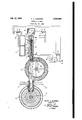
- the drawing shows a plan view of the invention in sectional detail and includes a wiring diagram for periodically operating the hydraulic ram and motor.
- the reamer device is collectively indicated at Z and comprises a hydraulic ram cylinder 65 having a reciprocating piston head 66 to which there is secured a tubular plunger Bl, which reciprocates through the head 68 of this ram.
- a sleeve 09 is rotatably mounted in this plunger and held in longitudinal relation thereto by the nut 10 and head 16.
- a motor 12 is mounted on the head ll of this ram and the motor shaft S passes through this head and is slidably mounted in the sleeve 69 by a, key 62 traveling in a key-way 61 as shown. It will thus be seen that the motor can be used to drive the sleeve 69 which is reciprocated by the piston head 68 and its attached plunger 64.
- a reamer shaft 1.5 Secured in the sleeve head 16, is a reamer shaft 1.5 which carries propellers 14 and a cutting head 13 which serves as the reamer tool.
- This cutting head may be of any suitable material suflicient- 1y hard for high speed cutting, as for instance, the commercially obtainable Carboloy is particularly satisfactory for the purpose.
- the described structure is mounted so as to operate through a separator G which is the same as disclosed in my aforesaid Patent No. 2,328,202 and need not be described here and is further connected by the flue F to the thermal reduction furnace E which is the same as in my aforesaid patent and need not be here described.
- the flue F is centered with the orifice of the furnace E and spray channels U and V each having a multiplicity of small apertures, are provided for spraying a liquid through either of the pipes 28 or 32 and preferably the liquid is atomized by a gas supplied through one of these pipes while the liquid is supplied through the other. It will be seen that the reamer head 13 will pass through this spray of liquid in entering and leaving the orifice of the furnace.
- the reciprocation of the ram is accomplished by pressure alternately supplied through the pipes 11 and 18 which are here shown connecting the ram to opposite sides of the double compartment tankv T which is preferably supplied with oil and selectively subjected to air pressure through the magnetic valve P which isof course connected to an air pressure line, and its exhaust pipe may lead to a receptacle for collecting any oil froth that may happen to form.
- This embodiment is preferable, but of course the pipes 11 and 10 could be connected directly to the valve P so as to operate the ram b air;pressure alone.
- the motor 12 may be constantly driven or any suitable means may be provided to stop the motor during each inactive period of the ram.
- two normally open switches 9 and Ill through which power is supplied when closed by the relay M which is connected to one terminal of a power source and the circuit is completed through the normally closed switch 8 which is held open by the piston head 66 when in its initial stationary position.
- the power source may be the terminals AB, but in the present instance separate terminals are shown, as it is sometimes desirable to use a 13-0 motor and an A-C valve, or vice versa.
- the clock K should operate to close the switch 4 at intervals of say about every five minutes, or less if desired.
- the ram should operate at sufflcient rate to complete its strokes in both directions in a few seconds.
- the magnesium metal issues from the thermal reduction furnace as a vapor and is shock cooled by a spray of liquid hydrocarbons so that the metal condenses in fine particles which are enveloped in globules of the unvaporized hydrocarbons so as to produce a thicksludge in the separator G.
- the propellers I4 wind their way through the flue, and as the reamer is withdrawn, the propellers 14 will effectively clear the flue of any accumulation of sludge so as to preclude accumulation on the flue walls.
- the' invention can be used to ream the oriflce of the furnace, and also to clear the flue F of any accumulation, and that the invention is operated at frequent intervals during the constant operation of the thermal reduction furnace, and that air is excluded from the system as is essentially necessary.
- the operation is entirely automatic, as is essentially necessary for utilizations ofthis kind where the equipment must be operated twenty-four. hours a day. for commercial practicability.
- a reamer shaft secured to the outer end of said sleeve, a cutting head and propeller blades secured to said shaft, an elongated shaft mounted within said sleeve and slidably engaged therewith by a key traveling in a keyway so as to rotate said sleeve during recipro-- cation thereof, a motor for driving the latter said shaft, an electromagnetic valve selectively supplying pressure to opposite ides of said piston, a self-locking relay for energizing said valve, a clock operated circuit for periodically energizing said relay, a normally closed switch opened by the stroke of said piston to break the circuit to said relay and reverse said valve, and a circuit for said motor including a normally closed switch held open by said-piston in its initial stationary position.
- An automatic reamer comprising a stationary cylinder having a pressure operated piston therein, a cutting head reciprocated by said piston, a motor rotating said cutting head, clock actuated means to periodically supply pressure to advance said piston means operated by said piston to reverse the pressure and return the piston to its initial position and hold the same stationary until the next period of operation, and means operated by said piston at its stationary position to render said motor inoperative while said piston is stationary.
- An automatic reamer comprising a motor driven cutting head including clock actuated means to periodically reciprocate the same into and out of an orifice to be reamed, a. receiving .chamber through which said reamer reciprocates.
- a flue for connecting said chamber to an orifice to be reamed, and propellers carried by said reamer for removing material from said flue and out into said receiving chamber.
- An automatic reamer comprising a piston within a cylinder, a tubular plunger carried by said piston, a sleeve rotatably mounted within said plunger and held against longitudinal movement relative thereto, a reamer shaft secured to the outer end of said sleeve, a cutting head secured to said shaft, an elongated shaft mounted within said sleeve and slidably engaged therewith by a key traveling in a keyway so as to rotate said sleeve during reciprocation thereof, a motor for driving the latter said shaft, an electromagnetic valve selectively supplying pressure to opposite sides of said piston, a self-locking relay for energizing said valve, a clock operated circuit for periodically energizing said relay, and a normally closed switch opened by the stroke of said piston to break the circuit to said relay and reverse said valve.
- An automatic reamer comprising a piston within a cylinder, a tubular plunger carried by said piston, a sleeve rotatably mounted within said plunger and held in longitudinal relation therewith, a reamer shaft fixed to said sleeve, a cutting head secured to the end of said shaft, a motor having a shaft slidably keyed inside said sleeve, clock actuated means for periodically supplying pressure to advance said piston, means operated by the stroke of said piston to reverse the same and return it to stationary position, and
- An automatic reamer comprising a piston within a cylinder, a tubular plunger carried by said piston, a sleeve rotatably mounted within said plunger and held in longitudinal relation therewith, a reamer shaft fixed to said sleeve, a cutting head secured to the end of said shaft, a motor having a shaft slidably keyed inside said sleeve, clock actuated means for periodically supplying pressure to advance said piston, and means operated by the stroke of said piston to reverse the same and return it to the initial position and hold the same stationary until the next period of operation;
- An automatic reamer comprising a hydraulic ram including a piston having a hollow plunger secured thereto, a sleeve rotatably mounted in said plunger and held in longitudinal relation therewith, a reamer shaft fixed to said sleeve, a cutting head secured to the end of said shaft, radially disposed propeller blades secured to said shaft, a motor having a shaft slida'bly keyed inside said sleeve, a casing through which said reamer reciprocates, a spray flue for connecting said casing to an orifice to be reamed, clock actuated means for periodically supplying pressure to advance the piston of said ram, and means operated by the stroke ofsaid piston to reverse the same and return it to the initial position and hold the same stationary until the next period of operation.
- An automatic reamer comprising a hydraulic ram including a piston having a hollow plunger secured thereto, a sleeve rotatably mounted in said plunger and held in longitudinal relation therewith, a reamershaft fixed to said sleeve, a cutting head secured to the end of said shaft,
- a motor having a shaft slidably keyed inside said sleeve, a casing throughwhich said reamer reciprocates, a spray flue for connecting said casing to an orifice to be reamed, clock actuated means forperiodically supplying pressure to advance the piston of said ram, and means operated by the stroke of said piston to reverse the same and return it to the initial position and hold the same stationary until the next period of operation.
- An automatic reamer comprising a hydraulic ram including-a piston having a hollow plunger secured thereto, a sleeve rotatably mounted in said plunger and held in longitudinal relation therewith, a reamer shaft fixed to said sleeve, a
- a motor having a shaft slidably keyed insidesaid sleeve, a casing through which said reamer reciprocates, a spray flue for connecting said casing to an orifice to be reamed, clock-actuated means for periodically supplying pressure to advance the piston of said ram, means operated by the stroke of said piston to reverse the same and return it to stationary position, and a self closing switch held open by said piston at its stationary position so as to operate said motor only during the movements of said piston.
- An automatic reamer comprising a piston within a cylinder, a tubular plunger carried by said piston, a sleeve rotatably mounted within said plunger and held against longitudinal movement relative thereto, a reamer shaft secured to the outer end of said sleeve, a cutting head secured to said shaft, an elongated shaft mounted within said sleeve and slidably engaged therewith by a key traveling in a keyway so as to rotate said sleeve during reciprocation thereof, a motor for driving the latter said shaft, and means to reciprocate said piston.
- An automatic reamer comprising a station-- ary cylinder having a pressure operated piston therein, a cutting tool reciprocated by said piston, a motor for rotating said cutting tool, an electromagnetic valve selectively supplying pressure to opposite sides of said piston, a self-locking relay for energizing said valve, a clock operated circ-uit for periodically energizing said relay, and a normally closed switch opened by the stroke of said piston to break the circuit to, said relay and reverse said valve.
- An automatic reamer comprising a stationary cylinder having a. pressure operated piston therein, a cutting tool reciprocated by-said piston,
- a motor for rotating said cutting tool an electromagnetic valve selectively supplying pressure to opposite sides of said piston, a self-locking relay for energizing said valve, a clock operated circuit for periodically energizing said relay, a normally closed switch opened by the stroke of said piston to break the circuit to said relay and reverse said valve, and a circuit for said motor including a normally closed switch-held open by said piston in its initial stationary position, so that said motor operates only during the reciprocation of said piston.
Landscapes
- Engineering & Computer Science (AREA)
- Mechanical Engineering (AREA)
- General Engineering & Computer Science (AREA)
- Actuator (AREA)
Description
H. A. DOERNER AUTOMATIC REAMER July 10, 1945.
Filed Jan. 23, 1943 HENRY A. .DOERNER INVENTOR I ATTORNEY Patented July lO, 1945 UNITED STATES PAT ENT OFFICE 2,380,098 I AUTOMATIC BEAMER Henry A. Doerner, Pullman, Wash.
Application January 23, 1943, Serial No. 473,325
12 Claims.
The present invention relates to certain new and useful improvements in an automatic reamer for keeping the orifice of a thermal reduction furnace free of deposits which congeal in the orifice at high temperatures well above the melting point of most metals.
The invention was a part of my application Serial No. 372,293 filed December 30, 1940, which matured into Patent No. 2,328,202 issued August 31, 1943, for a Process of producing magnesium metal, and is particularly eflicient for that special purpose.
In the thermal reduction of MgO and carbon to form magnesium metal, the reaction temperature is about 2000 centigrade and there occurs some vaporization of the traces of silica which is usually present in the original material. This vaporized silica congeals in the orifice of the thermal reduction furnace and forms a hard deposit which also contains some carbon and some MgO due to slight reversal of reaction and to minor escape of particles of the original charge. Unless constantly removed, this hard deposit gradually accumulates in the orifice and will soon completely block the outlet of the thermal reduction products, and render the equipment inoperable.
The present invention provides a motor driven reamer which is periodically reciprocated by a hydraulic ram so as to frequently ream out the orifice by quickly inserting and withdrawing the rotating reamer. Means are provided to supply a spray of liquid outside the orifice so that the reamer is cooled as it enters and leaves the orifice. During the-inactive periods, the reamer is retracted to a convenient distance so as not to interfere with the output of the thermal reduction products. The interval between the periodic reciprocations of the reamer is controlled by a clock mechanism, and means are provided for the ram to automatically reverse itself at the end of the advance stroke of the reamer.
The reamer is arranged so as to operate through a receiving chamber or separator, into which the thermal reduction products are received. and the entire equipment is completely enclosed so as to exclude air from the system, as is essentially necessary in the production of magnesium metal by thermal reduction of MgO and carbon.
The drawing shows a plan view of the invention in sectional detail and includes a wiring diagram for periodically operating the hydraulic ram and motor.
The reamer device is collectively indicated at Z and comprises a hydraulic ram cylinder 65 having a reciprocating piston head 66 to which there is secured a tubular plunger Bl, which reciprocates through the head 68 of this ram. A sleeve 09 is rotatably mounted in this plunger and held in longitudinal relation thereto by the nut 10 and head 16. A motor 12 is mounted on the head ll of this ram and the motor shaft S passes through this head and is slidably mounted in the sleeve 69 by a, key 62 traveling in a key-way 61 as shown. It will thus be seen that the motor can be used to drive the sleeve 69 which is reciprocated by the piston head 68 and its attached plunger 64. Secured in the sleeve head 16, is a reamer shaft 1.5 which carries propellers 14 and a cutting head 13 which serves as the reamer tool. This cutting head may be of any suitable material suflicient- 1y hard for high speed cutting, as for instance, the commercially obtainable Carboloy is particularly satisfactory for the purpose.
The described structure is mounted so as to operate through a separator G which is the same as disclosed in my aforesaid Patent No. 2,328,202 and need not be described here and is further connected by the flue F to the thermal reduction furnace E which is the same as in my aforesaid patent and need not be here described. The flue F is centered with the orifice of the furnace E and spray channels U and V each having a multiplicity of small apertures, are provided for spraying a liquid through either of the pipes 28 or 32 and preferably the liquid is atomized by a gas supplied through one of these pipes while the liquid is supplied through the other. It will be seen that the reamer head 13 will pass through this spray of liquid in entering and leaving the orifice of the furnace.
The reciprocation of the ram is accomplished by pressure alternately supplied through the pipes 11 and 18 which are here shown connecting the ram to opposite sides of the double compartment tankv T which is preferably supplied with oil and selectively subjected to air pressure through the magnetic valve P which isof course connected to an air pressure line, and its exhaust pipe may lead to a receptacle for collecting any oil froth that may happen to form. This embodiment is preferable, but of course the pipes 11 and 10 could be connected directly to the valve P so as to operate the ram b air;pressure alone.
To provide for periodic energizing of the valve P it is connected to the current supply A and the circuit is completed to the line B through the normally open switch 6 which is closed by energizing therelay R. The line A is directly connected to the relay R and the circuit is completed through the normally open switch 4 which is periodically closed by the-clock mechanism K which is here shown as supplied with current from current to operate the valve P to provide pres-,
sure through the pipe 18 to move the piston 66 forward until its full stroke opens the switch 3 and breaks the circuit to the relay R and open the switch 6 so as to reverse the valve P and supply pressure through the pipe 11 to the opposite side of the piston and return it to its initial position, where it remains until the clock K again closes the switch 4.
The motor 12 may be constantly driven or any suitable means may be provided to stop the motor during each inactive period of the ram. In the present instance there is shown two normally open switches 9 and Ill through which power is supplied when closed by the relay M which is connected to one terminal of a power source and the circuit is completed through the normally closed switch 8 which is held open by the piston head 66 when in its initial stationary position. The power source may be the terminals AB, but in the present instance separate terminals are shown, as it is sometimes desirable to use a 13-0 motor and an A-C valve, or vice versa.
In operation it is necessary that the reamer head 13 enter and leave the orifice very quickly, because otherwise most cutting tools would not withstand the high temperature. This necessitates that the reaming be done frequently, be cause otherwise the accumulation in the orifice would be too much to be cut away quickly. For this reason the clock K should operate to close the switch 4 at intervals of say about every five minutes, or less if desired. The ram should operate at sufflcient rate to complete its strokes in both directions in a few seconds.
As disclosed in my aforesaid Patent No. 2,328,202, the magnesium metal issues from the thermal reduction furnace as a vapor and is shock cooled by a spray of liquid hydrocarbons so that the metal condenses in fine particles which are enveloped in globules of the unvaporized hydrocarbons so as to produce a thicksludge in the separator G. In the operation of the present invention, as the reamer passes through the flue F the propellers I4 wind their way through the flue, and as the reamer is withdrawn, the propellers 14 will effectively clear the flue of any accumulation of sludge so as to preclude accumulation on the flue walls.
From the described operation it will be seen that the' invention can be used to ream the oriflce of the furnace, and also to clear the flue F of any accumulation, and that the invention is operated at frequent intervals during the constant operation of the thermal reduction furnace, and that air is excluded from the system as is essentially necessary. The operation is entirely automatic, as is essentially necessary for utilizations ofthis kind where the equipment must be operated twenty-four. hours a day. for commercial practicability.
said plunger and held against longitudinal movement relative thereto, a reamer shaft secured to the outer end of said sleeve, a cutting head and propeller blades secured to said shaft, an elongated shaft mounted within said sleeve and slidably engaged therewith by a key traveling in a keyway so as to rotate said sleeve during recipro-- cation thereof, a motor for driving the latter said shaft, an electromagnetic valve selectively supplying pressure to opposite ides of said piston, a self-locking relay for energizing said valve, a clock operated circuit for periodically energizing said relay, a normally closed switch opened by the stroke of said piston to break the circuit to said relay and reverse said valve, and a circuit for said motor including a normally closed switch held open by said-piston in its initial stationary position.
2. An automatic reamer comprising a stationary cylinder having a pressure operated piston therein, a cutting head reciprocated by said piston, a motor rotating said cutting head, clock actuated means to periodically supply pressure to advance said piston means operated by said piston to reverse the pressure and return the piston to its initial position and hold the same stationary until the next period of operation, and means operated by said piston at its stationary position to render said motor inoperative while said piston is stationary.
3. An automatic reamer comprising a motor driven cutting head including clock actuated means to periodically reciprocate the same into and out of an orifice to be reamed, a. receiving .chamber through which said reamer reciprocates.
a flue for connecting said chamber to an orifice to be reamed, and propellers carried by said reamer for removing material from said flue and out into said receiving chamber.
4. An automatic reamer comprising a piston within a cylinder, a tubular plunger carried by said piston, a sleeve rotatably mounted within said plunger and held against longitudinal movement relative thereto, a reamer shaft secured to the outer end of said sleeve, a cutting head secured to said shaft, an elongated shaft mounted within said sleeve and slidably engaged therewith by a key traveling in a keyway so as to rotate said sleeve during reciprocation thereof, a motor for driving the latter said shaft, an electromagnetic valve selectively supplying pressure to opposite sides of said piston, a self-locking relay for energizing said valve, a clock operated circuit for periodically energizing said relay, and a normally closed switch opened by the stroke of said piston to break the circuit to said relay and reverse said valve.
5. An automatic reamer comprising a piston within a cylinder, a tubular plunger carried by said piston, a sleeve rotatably mounted within said plunger and held in longitudinal relation therewith, a reamer shaft fixed to said sleeve, a cutting head secured to the end of said shaft, a motor having a shaft slidably keyed inside said sleeve, clock actuated means for periodically supplying pressure to advance said piston, means operated by the stroke of said piston to reverse the same and return it to stationary position, and
motor only during the movements of said piston.
6. An automatic reamer comprising a piston within a cylinder, a tubular plunger carried by said piston, a sleeve rotatably mounted within said plunger and held in longitudinal relation therewith, a reamer shaft fixed to said sleeve, a cutting head secured to the end of said shaft, a motor having a shaft slidably keyed inside said sleeve, clock actuated means for periodically supplying pressure to advance said piston, and means operated by the stroke of said piston to reverse the same and return it to the initial position and hold the same stationary until the next period of operation;
7. An automatic reamer comprising a hydraulic ram including a piston having a hollow plunger secured thereto, a sleeve rotatably mounted in said plunger and held in longitudinal relation therewith, a reamer shaft fixed to said sleeve, a cutting head secured to the end of said shaft, radially disposed propeller blades secured to said shaft, a motor having a shaft slida'bly keyed inside said sleeve, a casing through which said reamer reciprocates, a spray flue for connecting said casing to an orifice to be reamed, clock actuated means for periodically supplying pressure to advance the piston of said ram, and means operated by the stroke ofsaid piston to reverse the same and return it to the initial position and hold the same stationary until the next period of operation.
8. An automatic reamer comprising a hydraulic ram including a piston having a hollow plunger secured thereto, a sleeve rotatably mounted in said plunger and held in longitudinal relation therewith, a reamershaft fixed to said sleeve, a cutting head secured to the end of said shaft,
' a motor having a shaft slidably keyed inside said sleeve, a casing throughwhich said reamer reciprocates, a spray flue for connecting said casing to an orifice to be reamed, clock actuated means forperiodically supplying pressure to advance the piston of said ram, and means operated by the stroke of said piston to reverse the same and return it to the initial position and hold the same stationary until the next period of operation.
9. An automatic reamer comprising a hydraulic ram including-a piston having a hollow plunger secured thereto, a sleeve rotatably mounted in said plunger and held in longitudinal relation therewith, a reamer shaft fixed to said sleeve, a
cutting head secured to the end of said shaft, a motor having a shaft slidably keyed insidesaid sleeve, a casing through which said reamer reciprocates, a spray flue for connecting said casing to an orifice to be reamed, clock-actuated means for periodically supplying pressure to advance the piston of said ram, means operated by the stroke of said piston to reverse the same and return it to stationary position, and a self closing switch held open by said piston at its stationary position so as to operate said motor only during the movements of said piston.
10. An automatic reamer comprising a piston within a cylinder, a tubular plunger carried by said piston, a sleeve rotatably mounted within said plunger and held against longitudinal movement relative thereto, a reamer shaft secured to the outer end of said sleeve, a cutting head secured to said shaft, an elongated shaft mounted within said sleeve and slidably engaged therewith by a key traveling in a keyway so as to rotate said sleeve during reciprocation thereof, a motor for driving the latter said shaft, and means to reciprocate said piston.
11. An automatic reamer comprising a station-- ary cylinder having a pressure operated piston therein, a cutting tool reciprocated by said piston, a motor for rotating said cutting tool, an electromagnetic valve selectively supplying pressure to opposite sides of said piston, a self-locking relay for energizing said valve, a clock operated circ-uit for periodically energizing said relay, and a normally closed switch opened by the stroke of said piston to break the circuit to, said relay and reverse said valve. 12. An automatic reamer comprising a stationary cylinder having a. pressure operated piston therein, a cutting tool reciprocated by-said piston,
a motor for rotating said cutting tool, an electromagnetic valve selectively supplying pressure to opposite sides of said piston, a self-locking relay for energizing said valve, a clock operated circuit for periodically energizing said relay, a normally closed switch opened by the stroke of said piston to break the circuit to said relay and reverse said valve, and a circuit for said motor including a normally closed switch-held open by said piston in its initial stationary position, so that said motor operates only during the reciprocation of said piston.
HENRY A. DOERNER.
Priority Applications (1)
| Application Number | Priority Date | Filing Date | Title |
|---|---|---|---|
| US473325A US2380098A (en) | 1943-01-23 | 1943-01-23 | Automatic reamer |
Applications Claiming Priority (1)
| Application Number | Priority Date | Filing Date | Title |
|---|---|---|---|
| US473325A US2380098A (en) | 1943-01-23 | 1943-01-23 | Automatic reamer |
Publications (1)
| Publication Number | Publication Date |
|---|---|
| US2380098A true US2380098A (en) | 1945-07-10 |
Family
ID=23879089
Family Applications (1)
| Application Number | Title | Priority Date | Filing Date |
|---|---|---|---|
| US473325A Expired - Lifetime US2380098A (en) | 1943-01-23 | 1943-01-23 | Automatic reamer |
Country Status (1)
| Country | Link |
|---|---|
| US (1) | US2380098A (en) |
Cited By (21)
| Publication number | Priority date | Publication date | Assignee | Title |
|---|---|---|---|---|
| US2696979A (en) * | 1951-04-16 | 1954-12-14 | Kennecott Copper Corp | Automatic tuyere punching apparatus |
| US2803842A (en) * | 1955-10-07 | 1957-08-27 | California Research Corp | Heat exchanger tube reamer |
| US2971897A (en) * | 1957-06-28 | 1961-02-14 | Chapman Bernard | Water distillation plant designed for automatic continuous operation |
| US4321096A (en) * | 1980-12-16 | 1982-03-23 | John B. Pike & Son, Inc. | Apparatus and method for cleaning an explosion sensing port |
| US4711013A (en) * | 1985-04-03 | 1987-12-08 | Advanced Thermal Systems, Inc. | Method for removing injectable material from a packing cylinder |
| US20090266380A1 (en) * | 2008-04-25 | 2009-10-29 | Barry Freel | Mitigation of deposits and secondary reactions in thermal conversion processes |
| US8961743B2 (en) | 2007-11-20 | 2015-02-24 | Ensyn Renewables, Inc. | Rapid thermal conversion of biomass |
| US9044727B2 (en) | 2011-09-22 | 2015-06-02 | Ensyn Renewables, Inc. | Apparatuses and methods for controlling heat for rapid thermal processing of carbonaceous material |
| US9102888B2 (en) | 2011-12-12 | 2015-08-11 | Ensyn Renewables, Inc. | Methods for renewable fuels with reduced waste streams |
| US9127208B2 (en) | 2006-04-03 | 2015-09-08 | Pharmatherm Chemicals, Inc. | Thermal extraction method and product |
| US9347005B2 (en) | 2011-09-13 | 2016-05-24 | Ensyn Renewables, Inc. | Methods and apparatuses for rapid thermal processing of carbonaceous material |
| US9422478B2 (en) | 2010-07-15 | 2016-08-23 | Ensyn Renewables, Inc. | Char-handling processes in a pyrolysis system |
| US9441887B2 (en) | 2011-02-22 | 2016-09-13 | Ensyn Renewables, Inc. | Heat removal and recovery in biomass pyrolysis |
| US9670413B2 (en) | 2012-06-28 | 2017-06-06 | Ensyn Renewables, Inc. | Methods and apparatuses for thermally converting biomass |
| US9951278B2 (en) | 2010-05-20 | 2018-04-24 | Ensyn Renewables, Inc. | Processes for controlling afterburn in a reheater and for controlling loss of entrained solid particles in combustion product flue gas |
| US10041667B2 (en) | 2011-09-22 | 2018-08-07 | Ensyn Renewables, Inc. | Apparatuses for controlling heat for rapid thermal processing of carbonaceous material and methods for the same |
| US10337726B2 (en) | 2015-08-21 | 2019-07-02 | Ensyn Renewables, Inc. | Liquid biomass heating system |
| US10400176B2 (en) | 2016-12-29 | 2019-09-03 | Ensyn Renewables, Inc. | Demetallization of liquid biomass |
| US10400175B2 (en) | 2011-09-22 | 2019-09-03 | Ensyn Renewables, Inc. | Apparatuses and methods for controlling heat for rapid thermal processing of carbonaceous material |
| US10633606B2 (en) | 2012-12-10 | 2020-04-28 | Ensyn Renewables, Inc. | Systems and methods for renewable fuel |
| US20230158556A1 (en) * | 2020-04-23 | 2023-05-25 | Btg Bioliquids B.V. | Pyrolysis Vapour Condenser System and Method of Condensing Pyrolysis Vapour |
-
1943
- 1943-01-23 US US473325A patent/US2380098A/en not_active Expired - Lifetime
Cited By (49)
| Publication number | Priority date | Publication date | Assignee | Title |
|---|---|---|---|---|
| US2696979A (en) * | 1951-04-16 | 1954-12-14 | Kennecott Copper Corp | Automatic tuyere punching apparatus |
| US2803842A (en) * | 1955-10-07 | 1957-08-27 | California Research Corp | Heat exchanger tube reamer |
| US2971897A (en) * | 1957-06-28 | 1961-02-14 | Chapman Bernard | Water distillation plant designed for automatic continuous operation |
| US4321096A (en) * | 1980-12-16 | 1982-03-23 | John B. Pike & Son, Inc. | Apparatus and method for cleaning an explosion sensing port |
| US4711013A (en) * | 1985-04-03 | 1987-12-08 | Advanced Thermal Systems, Inc. | Method for removing injectable material from a packing cylinder |
| US9127208B2 (en) | 2006-04-03 | 2015-09-08 | Pharmatherm Chemicals, Inc. | Thermal extraction method and product |
| US9809564B2 (en) | 2006-04-03 | 2017-11-07 | Pharmatherm Chemicals, Inc. | Thermal extraction method and product |
| US8961743B2 (en) | 2007-11-20 | 2015-02-24 | Ensyn Renewables, Inc. | Rapid thermal conversion of biomass |
| US9631145B2 (en) | 2007-11-20 | 2017-04-25 | Ensyn Renewables, Inc. | Rapid thermal conversion of biomass |
| US10544368B2 (en) | 2007-11-20 | 2020-01-28 | Ensyn Renewables, Inc. | Rapid thermal conversion of biomass |
| US20100236915A1 (en) * | 2008-04-25 | 2010-09-23 | Ensyn Renewables, Inc. | Mitigation of deposits and secondary reactions in thermal conversion processes |
| EP2907865A1 (en) * | 2008-04-25 | 2015-08-19 | Ensyn Renewables, Inc. | Mitigation of deposits and secondary reactions in thermal conversion |
| US8726443B2 (en) * | 2008-04-25 | 2014-05-20 | Ensyn Renewables, Inc. | Mitigation of deposits and secondary reactions in thermal conversion processes |
| US20090266380A1 (en) * | 2008-04-25 | 2009-10-29 | Barry Freel | Mitigation of deposits and secondary reactions in thermal conversion processes |
| US8097090B2 (en) * | 2008-04-25 | 2012-01-17 | Ensyn Renewables Inc. | Mitigation of deposits and secondary reactions in thermal conversion processes |
| EP2303990A4 (en) * | 2008-04-25 | 2013-01-02 | Ensyn Renewables Inc | REDUCING DEPOSITS AND SECONDARY REACTIONS DURING THERMAL CONVERSION PROCESSES |
| US9951278B2 (en) | 2010-05-20 | 2018-04-24 | Ensyn Renewables, Inc. | Processes for controlling afterburn in a reheater and for controlling loss of entrained solid particles in combustion product flue gas |
| US10563127B2 (en) | 2010-05-20 | 2020-02-18 | Ensyn Renewables, Inc. | Processes for controlling afterburn in a reheater and for controlling loss of entrained solid particles in combustion product flue gas |
| US9422478B2 (en) | 2010-07-15 | 2016-08-23 | Ensyn Renewables, Inc. | Char-handling processes in a pyrolysis system |
| US9441887B2 (en) | 2011-02-22 | 2016-09-13 | Ensyn Renewables, Inc. | Heat removal and recovery in biomass pyrolysis |
| US11028325B2 (en) | 2011-02-22 | 2021-06-08 | Ensyn Renewables, Inc. | Heat removal and recovery in biomass pyrolysis |
| US9347005B2 (en) | 2011-09-13 | 2016-05-24 | Ensyn Renewables, Inc. | Methods and apparatuses for rapid thermal processing of carbonaceous material |
| US10400175B2 (en) | 2011-09-22 | 2019-09-03 | Ensyn Renewables, Inc. | Apparatuses and methods for controlling heat for rapid thermal processing of carbonaceous material |
| US10041667B2 (en) | 2011-09-22 | 2018-08-07 | Ensyn Renewables, Inc. | Apparatuses for controlling heat for rapid thermal processing of carbonaceous material and methods for the same |
| US9044727B2 (en) | 2011-09-22 | 2015-06-02 | Ensyn Renewables, Inc. | Apparatuses and methods for controlling heat for rapid thermal processing of carbonaceous material |
| US10794588B2 (en) | 2011-09-22 | 2020-10-06 | Ensyn Renewables, Inc. | Apparatuses for controlling heat for rapid thermal processing of carbonaceous material and methods for the same |
| US9102888B2 (en) | 2011-12-12 | 2015-08-11 | Ensyn Renewables, Inc. | Methods for renewable fuels with reduced waste streams |
| US9120990B2 (en) | 2011-12-12 | 2015-09-01 | Ensyn Renewables, Inc. | Systems for fuels from biomass |
| US9410091B2 (en) | 2011-12-12 | 2016-08-09 | Ensyn Renewables, Inc. | Preparing a fuel from liquid biomass |
| US9102890B2 (en) | 2011-12-12 | 2015-08-11 | Ensyn Renewables, Inc. | Fluidized catalytic cracking apparatus |
| US9127223B2 (en) | 2011-12-12 | 2015-09-08 | Ensyn Renewables, Inc. | Systems and methods for renewable fuel |
| US9127224B2 (en) | 2011-12-12 | 2015-09-08 | Ensyn Renewables, Inc. | External steam reduction method in a fluidized catalytic cracker |
| US9969942B2 (en) | 2011-12-12 | 2018-05-15 | Ensyn Renewables, Inc. | Systems and methods for renewable fuel |
| US9120989B2 (en) | 2011-12-12 | 2015-09-01 | Ensyn Renewables, Inc. | Generating cellulosic-renewable identification numbers in a refinery |
| US10975315B2 (en) | 2011-12-12 | 2021-04-13 | Ensyn Renewables, Inc. | Systems and methods for renewable fuel |
| US9102889B2 (en) | 2011-12-12 | 2015-08-11 | Ensyn Renewables, Inc. | Fluidized catalytic cracker riser quench system |
| US9120988B2 (en) | 2011-12-12 | 2015-09-01 | Ensyn Renewables, Inc. | Methods to increase gasoline yield |
| US9422485B2 (en) | 2011-12-12 | 2016-08-23 | Ensyn Renewables, Inc. | Method of trading cellulosic-renewable identification numbers |
| US9109177B2 (en) | 2011-12-12 | 2015-08-18 | Ensyn Renewables, Inc. | Systems and methods for renewable fuel |
| US10570340B2 (en) | 2011-12-12 | 2020-02-25 | Ensyn Renewables, Inc. | Systems and methods for renewable fuel |
| US9670413B2 (en) | 2012-06-28 | 2017-06-06 | Ensyn Renewables, Inc. | Methods and apparatuses for thermally converting biomass |
| US10633606B2 (en) | 2012-12-10 | 2020-04-28 | Ensyn Renewables, Inc. | Systems and methods for renewable fuel |
| US10640719B2 (en) | 2013-06-26 | 2020-05-05 | Ensyn Renewables, Inc. | Systems and methods for renewable fuel |
| US10948179B2 (en) | 2015-08-21 | 2021-03-16 | Ensyn Renewables, Inc. | Liquid biomass heating system |
| US10337726B2 (en) | 2015-08-21 | 2019-07-02 | Ensyn Renewables, Inc. | Liquid biomass heating system |
| US10400176B2 (en) | 2016-12-29 | 2019-09-03 | Ensyn Renewables, Inc. | Demetallization of liquid biomass |
| US10982152B2 (en) | 2016-12-29 | 2021-04-20 | Ensyn Renewables, Inc. | Demetallization of liquid biomass |
| US20230158556A1 (en) * | 2020-04-23 | 2023-05-25 | Btg Bioliquids B.V. | Pyrolysis Vapour Condenser System and Method of Condensing Pyrolysis Vapour |
| US12434279B2 (en) * | 2020-04-23 | 2025-10-07 | Btg Bioliquids B.V. | Pyrolysis vapour condenser system and method of condensing pyrolysis vapour |
Similar Documents
| Publication | Publication Date | Title |
|---|---|---|
| US2380098A (en) | Automatic reamer | |
| US5599223A (en) | Method for material removal | |
| US5341608A (en) | Method and apparatus for material removal | |
| KR100829916B1 (en) | Flakes Compression For Dry Ice | |
| WO2003019068A8 (en) | Dewatering device and method for gas hydrate slurrys | |
| CN108284250A (en) | Steel pipe fixes cutter device | |
| US2490302A (en) | Means for removing embedded material | |
| US3173289A (en) | Automatic melting point measuring method and apparatus | |
| CN102873246A (en) | Hydraulic machine for forging and forming large-sized aluminium alloy wheel hub | |
| US3681930A (en) | Apparatus for making carbon dioxide snow | |
| CN103286630A (en) | Low-temperature atomizing air cooler and achieving method thereof | |
| CN116372285A (en) | An Efficient Milling Device for Anchor Fasteners | |
| US3070967A (en) | Dry ice manufacture | |
| CN112405171A (en) | Energy-concerving and environment-protective car clutch piece processingequipment | |
| CN208289141U (en) | One kind pushing away burr equipment | |
| US2675076A (en) | Control system and carriage moving means for flying cutoff apparatus | |
| EP0330687B1 (en) | Pneumatic linear vibrator | |
| CN209998292U (en) | rotary-pulling breaking-in tool | |
| US1642966A (en) | Apparatus for producing mold charges of molten glass | |
| CN202861294U (en) | Large aluminum alloy wheel hub forging molding hydraulic press | |
| US1905506A (en) | Broaching machine | |
| RU155758U1 (en) | BLASTING MACHINE | |
| CN203292942U (en) | Low-temperature atomization air cooler | |
| CN113198198A (en) | Waste lubricating oil retrieves and uses super large backward flow vacuum tower | |
| CN223863411U (en) | Cutting device for metal product processing |