US237828A - Tttddebeatteegaed - Google Patents
Tttddebeatteegaed Download PDFInfo
- Publication number
- US237828A US237828A US237828DA US237828A US 237828 A US237828 A US 237828A US 237828D A US237828D A US 237828DA US 237828 A US237828 A US 237828A
- Authority
- US
- United States
- Prior art keywords
- steam
- aspirator
- receptacle
- reservoir
- heat
- Prior art date
- Legal status (The legal status is an assumption and is not a legal conclusion. Google has not performed a legal analysis and makes no representation as to the accuracy of the status listed.)
- Expired - Lifetime
Links
- XLYOFNOQVPJJNP-UHFFFAOYSA-N water Substances O XLYOFNOQVPJJNP-UHFFFAOYSA-N 0.000 description 5
- 150000001875 compounds Chemical class 0.000 description 4
- 239000007789 gas Substances 0.000 description 3
- 239000007788 liquid Substances 0.000 description 3
- 238000009833 condensation Methods 0.000 description 2
- 230000005494 condensation Effects 0.000 description 2
- 239000012530 fluid Substances 0.000 description 2
- 239000000203 mixture Substances 0.000 description 2
- 238000009835 boiling Methods 0.000 description 1
- 239000003795 chemical substances by application Substances 0.000 description 1
- 229940000425 combination drug Drugs 0.000 description 1
- 238000004891 communication Methods 0.000 description 1
- 238000010276 construction Methods 0.000 description 1
- 230000003292 diminished effect Effects 0.000 description 1
- 230000000694 effects Effects 0.000 description 1
- 238000002474 experimental method Methods 0.000 description 1
- 239000000446 fuel Substances 0.000 description 1
- 238000010438 heat treatment Methods 0.000 description 1
- 230000003137 locomotive effect Effects 0.000 description 1
- 239000000463 material Substances 0.000 description 1
- 230000008929 regeneration Effects 0.000 description 1
- 238000011069 regeneration method Methods 0.000 description 1
- 238000011160 research Methods 0.000 description 1
- 229920006395 saturated elastomer Polymers 0.000 description 1
- 238000009834 vaporization Methods 0.000 description 1
- 230000008016 vaporization Effects 0.000 description 1
- 239000002699 waste material Substances 0.000 description 1
Images

Classifications
-
- F—MECHANICAL ENGINEERING; LIGHTING; HEATING; WEAPONS; BLASTING
- F22—STEAM GENERATION
- F22B—METHODS OF STEAM GENERATION; STEAM BOILERS
- F22B3/00—Other methods of steam generation; Steam boilers not provided for in other groups of this subclass
- F22B3/04—Other methods of steam generation; Steam boilers not provided for in other groups of this subclass by drop in pressure of high-pressure hot water within pressure-reducing chambers, e.g. in accumulators
-
- B—PERFORMING OPERATIONS; TRANSPORTING
- B61—RAILWAYS
- B61C—LOCOMOTIVES; MOTOR RAILCARS
- B61C15/00—Maintaining or augmenting the starting or braking power by auxiliary devices and measures; Preventing wheel slippage; Controlling distribution of tractive effort between driving wheels
- B61C15/02—Maintaining or augmenting the starting or braking power by auxiliary devices and measures; Preventing wheel slippage; Controlling distribution of tractive effort between driving wheels by auxiliary driving wheels; by temporary coupling or use of fly wheels or booster engines
Definitions
- the primary source of the motive power is an object of the present invention.
- the steam is prevented from escaping from the circulation in the motor, and is maintained, as much as possible, in the aeriform state, by adding to it at each round the amount ot' heat usefully expendedthat is to say, the
- the present invention consists in the new combinations and dispositions ot' apparatus hereinafter explained, whereby certain difficulties inl the practical and industrial application of a dynamic cycle, or system ot' employing again and again the same steam or vapor, are overcome.
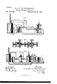
- Fig. l is a view, in section, of the apparatus employed with a simple engine
- Fig. 2 a view, partly in section, of the apparatus used with a compound engine
- Fig. 3 a sectional view, on a large scale, of two connected aspirators.
- the boiler Aand motor-cylinder B, with its slide-"alve C andpston D, are of ordinary or suitable construction, and need not be here described. Between them are placed the reservoir E and the equilibrium apparatus or partial condenser F..
- a pipe,G, from the boiler is provided with an aspirator, H, within the reservoir.
- the pipe I forms a continuation of said pipe G, and is in communication at its farther end with theinterior of the valve-chest.
- the pipe J is connected at one end with the outlet-port and at the other with the vessel K, having tubular passages extending through it.
- This vessel is surrounded with water in the receptacle F, and operates as a partial condenser. From the upper part of said vessel the uncondensed steam enters a second aspirator, N, which, by the aid of ajet of steam from the boiler by the pipe P, forces it into the reservoir E.
- the aspirators H and N are both provided with self-closing valves h and a, which prevent the passage of the steam backward.
- the steam after operating in the cylinder, in place of being conveyed directly to the reservoir, as in the theoretical system first explained, passes into the vessel K, placed in the receptacle F and surrounded by boiling water, and thence through the aspirator N into the reservoir.
- the water in receptacle F absorbs the heat left free, and permits it to be returned in the form of steam to the tire, the upper part of the IOO receptacle being connected with the nre-chamber.
- the aspirator N in forcing the steam into the receiver reheats it, and thus enables it to be more readily drawn in by the aspirator H.
- the small quantity of high temperature steam taken from the boiler is utilized iu two ways first, for the preliminary heating of the steam by the aspirator N, and, second, for its regenera tion by the aspirator H, which forces into the cylinder C the mixture constituting positive77 steam.
- this mixture is with saturated steam, for at the slightly elevated temperature (1400 centigrade, for example) which is maintained in the receiver, if the steam were dry, it would act as a gas, and would have only a feeble expansive force.
- an aspirator, S is placed between the cylinders B B' of the engine, and serves to give increased heat and pressure to the steam as it escapes from the small cylinder B, after having operated therein, so that it acts with greater force in the large cylinder B.
- the aspirator H takes its steam from the reservoir E.
- a pipe, R, is also shown connecting the top of the receptacle F with the fire-chamber of the boiler, so as to convey the steam from the water in said receptacle to the fire in order to thus utilize the same.
- the aspirators shown in Fig. 2 are provided with self-closing valves, but the steam passes by two branch pipes to unite with the jet.
- aspirators can be connected in series, one following the other, so as to constitute an aspirator of multiple etfect.
- y In Fig. 3 H H are aspirators so connected, ach being provided with its valve h h.
- thermodynamic cycle with expansive iuids in its various applications. It is applicable to steamengines of all kinds and for all purposes-fixed, semi-stationary, movable, locomotive, marine, tramway, Snc. It can be applied, also, with suitable changes in the disposition of the apparatus, to various industrial uses requiring the employment and transfer of heat.
- thermo-dynamic cycle as described, the receptacle or equilibrium apparatus, in combination with the reservoir and other parts of said cycle, substantially as set forth.
Landscapes
- Engineering & Computer Science (AREA)
- Mechanical Engineering (AREA)
- Transportation (AREA)
- Physics & Mathematics (AREA)
- Thermal Sciences (AREA)
- General Engineering & Computer Science (AREA)
- Engine Equipment That Uses Special Cycles (AREA)
Description
(No Model.)
P. A. T. DE'BBAURBGARD.
Thermo-DynamicEngine. A No. 237,828. Patented Feb.15, 1881.
N. PETERS, PHDTD-UTHCGRAPHER. WASHINGTON. D C.
UNTTED STATES PATENT UEETEE.
FELIX A. T. DE BEAUREGARD, OF PARIS, FRANCE.
THERMO-DYNAMIC ENGINE.
SPECIFICATION forming part of Letters Patent No. 237,828, dated February 15, 1881, Application tiled November 5, 1880. (No model.) IPatented in France February lf, 1880.
To all whom it may concern:
Be it known that I, FELrx ALEXANDRE TEs- TUD DE BEAUREGARD, ofParis, in the Republic of France, have invented certain new and useful Improvements in Thermo-Dynamic Steam and other Engines, using gas or vapor as the motive agent, of which improvements the following is a specification.
I have heretofore demonstrated in former inventions the possibility and useful capacity of a continuous dynamic cycle with liquids-that is to say, a system of circulation which permits a liquid to obtain continuously from a suitable source the quantity of heat to be converted into mechanical work. In prosecuting my researches and experiments I have been led to devise a similar cycle with expansive iiuids, vapors, or gases, and to such a closed andcontinuous cycle the present invention has reference.
ln the following description the application of the improved system to steam-engines will be more particularly described. In these it is destined, to modify the operation radically with respect to the amount of work obtained from the heat expended.
Itis well known that in the engines in use the larger part of the heat supplied in the boiler is wasted, either by escape into the air or by means of the water used in condensation. The quantity of heat thus lost is none other than the latent heat of vaporization, and is measured by five hundred and forty calorics. From the formula of Regnault, 1:60650 +0.305t, it will be seen that this is about fourt'ths of all the heat employed to produce steam at the customary tension. To avoid this great loss, which corresponds to a veritable waste of fuel, the primary source of the motive power, is an object of the present invention; and to this end the steam is prevented from escaping from the circulation in the motor, and is maintained, as much as possible, in the aeriform state, by adding to it at each round the amount ot' heat usefully expendedthat is to say, the
amount which is converted into mechanical force during its operation and detention in the cylinder. In this way the new thermo-dynamic cycle is obtained. It should, however, be observed that heretofore various plans have been devised for reusing the exhaust by forcing it,
by the aid of an aspirator furnished with fresh steam, from a boiler.
The present invention consists in the new combinations and dispositions ot' apparatus hereinafter explained, whereby certain difficulties inl the practical and industrial application of a dynamic cycle, or system ot' employing again and again the same steam or vapor, are overcome.
In the accompanying drawings, which form a part of this specification, the application of the new system to an ordinary simple engine is illustrated iu Figure l, and to a compound engine in Fig. 2. Fig. l is a view, in section, of the apparatus employed with a simple engine; Fig. 2, a view, partly in section, of the apparatus used with a compound engine; and Fig. 3, a sectional view, on a large scale, of two connected aspirators.
The boiler Aand motor-cylinder B, with its slide-"alve C andpston D, are of ordinary or suitable construction, and need not be here described. Between them are placed the reservoir E and the equilibrium apparatus or partial condenser F..
A pipe,G, from the boiler is provided with an aspirator, H, within the reservoir. The pipe I forms a continuation of said pipe G, and is in communication at its farther end with theinterior of the valve-chest. The pipe J is connected at one end with the outlet-port and at the other with the vessel K, having tubular passages extending through it. This vessel is surrounded with water in the receptacle F, and operates as a partial condenser. From the upper part of said vessel the uncondensed steam enters a second aspirator, N, which, by the aid of ajet of steam from the boiler by the pipe P, forces it into the reservoir E. The aspirators H and N are both provided with self-closing valves h and a, which prevent the passage of the steam backward. The steam, after operating in the cylinder, in place of being conveyed directly to the reservoir, as in the theoretical system first explained, passes into the vessel K, placed in the receptacle F and surrounded by boiling water, and thence through the aspirator N into the reservoir. The water in receptacle F absorbs the heat left free, and permits it to be returned in the form of steam to the tire, the upper part of the IOO receptacle being connected with the nre-chamber. The aspirator N, in forcing the steam into the receiver reheats it, and thus enables it to be more readily drawn in by the aspirator H. It will be seen, therefore, that the small quantity of high temperature steam taken from the boiler is utilized iu two ways first, for the preliminary heating of the steam by the aspirator N, and, second, for its regenera tion by the aspirator H, which forces into the cylinder C the mixture constituting positive77 steam. It will be readily understood that this mixture is with saturated steam, for at the slightly elevated temperature (1400 centigrade, for example) which is maintained in the receiver, if the steam were dry, it would act as a gas, and would have only a feeble expansive force.
The explanation already given will serve to elucidate the application, which is based on thc salne principles as the preceding, to a compound engine, Fig. 2. rlhe important differences to be noted are as follows:
First, an aspirator, S, is placed between the cylinders B B' of the engine, and serves to give increased heat and pressure to the steam as it escapes from the small cylinder B, after having operated therein, so that it acts with greater force in the large cylinder B. The aspirator H, as before, takes its steam from the reservoir E.
Secondly, the steam which escapes from the receptacle oi" equilibrium F is returned to the reservoir, not by au aspirator, but by a pump, I?, which is supplied from a secondary receptacle, Q.
A pipe, R,is also shown connecting the top of the receptacle F with the fire-chamber of the boiler, so as to convey the steam from the water in said receptacle to the fire in order to thus utilize the same.
The aspirators shown in Fig. 2 are provided with self-closing valves, but the steam passes by two branch pipes to unite with the jet.
In the different applications of the cycle, aspirators can be connected in series, one following the other, so as to constitute an aspirator of multiple etfect.
y In Fig. 3 H H are aspirators so connected, ach being provided with its valve h h.
ceases The present invention covers the thermodynamic cycle with expansive iuids in its various applications. It is applicable to steamengines of all kinds and for all purposes-fixed, semi-stationary, movable, locomotive, marine, tramway, Snc. It can be applied, also, with suitable changes in the disposition of the apparatus, to various industrial uses requiring the employment and transfer of heat.
The forms, dimensions, and materials of the apparatus composing the cycle can be changed in accordance with the nature of the application without departing from thc spirit of the invention.
Having now fully explained the said invention and the manner of carrying the same into effect, what I claim isl. In combina-tion with an en gine-cylinder or other vessel in which the temperature and pressure of an expansive fluid are usefully diminished, the reservoir and two aspirators or forcingapparatns, one servingto force the fluid, after it has acted on the cylinder or vessel, into the reservoir, and the other to force the same thence into the said cylinder or vessel, substantially as described.
2. In a thermo-dynamic cycle, as described, the receptacle or equilibrium apparatus, in combination with the reservoir and other parts of said cycle, substantially as set forth.
3. In a compound engine, an aspirator located between the small and large cylinders and operating substantially as described.
4. In a steam-engine, a receptacle for effecting a partial condensation of' the steam from the cylinders by means of liquid therein contained, so arranged and connected with the fire-chamber of the boiler-furnace, by a suitable pipe or conduit, that the steam generated from said liquid is conveyed to the tire-chamber, substantially as described.
In witness whereof I have hereunto signed my name in the presence of two subscribing witnesses.
FELIX ALEXANDRE TESTUI) DE BEAUREGARD.
VitIiesses:
GEO. H. SCIDMORE, CnARLns MARDELn'r.
Publications (1)
| Publication Number | Publication Date |
|---|---|
| US237828A true US237828A (en) | 1881-02-15 |
Family
ID=2307185
Family Applications (1)
| Application Number | Title | Priority Date | Filing Date |
|---|---|---|---|
| US237828D Expired - Lifetime US237828A (en) | Tttddebeatteegaed |
Country Status (1)
| Country | Link |
|---|---|
| US (1) | US237828A (en) |
-
0
- US US237828D patent/US237828A/en not_active Expired - Lifetime
Similar Documents
| Publication | Publication Date | Title |
|---|---|---|
| US237828A (en) | Tttddebeatteegaed | |
| US653436A (en) | Steam-generator. | |
| US592144A (en) | Alfred hogg | |
| US153704A (en) | Improvement in injection steam-engines | |
| US695510A (en) | Steam-engine. | |
| US239955A (en) | Peters | |
| US592824A (en) | Compound engine | |
| US561429A (en) | Locomotive circulating exhaust attachm ent | |
| US360834A (en) | Oooooo | |
| US52078A (en) | Improvement in steam-engines | |
| US369922A (en) | Jacket for steam-cylinders | |
| US408784A (en) | Compressed-air engine | |
| US347104A (en) | Reciprocating steam-engine | |
| US140700A (en) | Improvement in brake mechanisms | |
| US667244A (en) | Steam-cylinder drain-valve. | |
| US116312A (en) | Improvement in steam-engines | |
| US405569A (en) | lapag-e | |
| US701921A (en) | Controlling the generation of steam. | |
| US425265A (en) | smith | |
| US610034A (en) | Gas-engine | |
| US442835A (en) | Engine | |
| US422111A (en) | Compound steam-engine | |
| US256826A (en) | Combined steam and compressed-air engine | |
| US207639A (en) | Improvement in reciprocating engines | |
| US499065A (en) | Compound locomotive-engine |