US2378024A - Strip coiling apparatus - Google Patents
Strip coiling apparatus Download PDFInfo
- Publication number
- US2378024A US2378024A US456657A US45665742A US2378024A US 2378024 A US2378024 A US 2378024A US 456657 A US456657 A US 456657A US 45665742 A US45665742 A US 45665742A US 2378024 A US2378024 A US 2378024A
- Authority
- US
- United States
- Prior art keywords
- core
- strip
- wheel
- shaft
- clutch
- Prior art date
- Legal status (The legal status is an assumption and is not a legal conclusion. Google has not performed a legal analysis and makes no representation as to the accuracy of the status listed.)
- Expired - Lifetime
Links
Images


Classifications
-
- B—PERFORMING OPERATIONS; TRANSPORTING
- B21—MECHANICAL METAL-WORKING WITHOUT ESSENTIALLY REMOVING MATERIAL; PUNCHING METAL
- B21C—MANUFACTURE OF METAL SHEETS, WIRE, RODS, TUBES, PROFILES OR LIKE SEMI-MANUFACTURED PRODUCTS OTHERWISE THAN BY ROLLING; AUXILIARY OPERATIONS USED IN CONNECTION WITH METAL-WORKING WITHOUT ESSENTIALLY REMOVING MATERIAL
- B21C47/00—Winding-up, coiling or winding-off metal wire, metal band or other flexible metal material characterised by features relevant to metal processing only
- B21C47/32—Tongs or gripping means specially adapted for reeling operations
Definitions
- This invention relates to improvements in strip coiling apparatus orwinding reels and its purpose is to provide a novel and eflicient winding core having means for holding the metal strip thereon by suction so that the strip may be readily gripped and held upon coming into engagement with the core-under pressure.
- this improved winding core capable of automatically gripping a metal strip, lends itself to use with particular advantage in the operation of winding 9. long flat strip of steel or other strip material into the form or a succession of spiral 'coils, with no interruption of the movement of the strip between successive winding operations.
- the principal object of the invention to provide a winding reel having a core equipped with suction devices adapted to grip and hold a metal strip when the strip is brought into engagement therewith under, pressure.
- a further object is to provide an improved winding core provided with suction cups which are capable of adjustment with respect to the surface of the core.
- Still another object i to provide a windmg core comprising suction cups which are resiliently mounted and are thereby capable of movement with respect to the surfaceof the core.
- Other objects relate 'to various features and arrartiegements which will appear more fully hereina r.
- Fig. 2 shows an end view of the apparatus illustrated in Fi l
- Fig. 3 shows an enlarged sectional view taken on the line 33 of Fig. 2;
- Fig. 4 shows an enlarged side elevation of the valve mechanism for controlling the positioning of the rotatable wheel or carrier on which the cores or winding reels are mounted;
- Fig. 5 shows a sectional view taken on the irregular line 5-5 of Fig. 1;
- Fig. 6 shows a sectional view taken on the line 8-8 of Fig. 1;
- Fig. '7 is a detailed section taken on the line Fig. 8 is an enlarged sectional view through one Fig. 9 is a transverse sectionsthrough one of the cutter bars and its cutter, one of these cutters being mounted for movement adjacent each of the winding cores;
- Fig.'10 shows'an end elevation of one of the winding cores, illustrating the mechanism by which it may be contracted to release acoil of strip material wound thereon;
- Fig. 11 is an enlargement of a portion of the sectional view of Fig. 8, with the mounting of one oi. the suction cups. of the winding reel also shown in radial section;
- Fig. 12 shows an axial section through one of the winding cores on the line I 2-l 2 of Fig. 8, showing-the condition of the parts when the coreis expanded;
- Fig. 13 is a partial sectional view similar to.
- Fig. 14 shows an axial section through one of the friction clutches bywhich the winding cores are rotated, the section being taken on the line
- Fig. 15 is a perspective view of two complementary air valve members for controlling the admission of compressed air or other fluid to the cylinders by which the cutter bars are operated:
- Fig. 16 shows an enlarged transverse section I through the valve mechanism which is partially illustrated in Fig. 2, showing the means by which the admission or compressed air to the supply con- Figure 1 shows a side elevation of one form .of I
- strip coiling apparatus embodying the improved core of the present invention and ca.-
- Fig. 17 shows ase'ctional view taken on the line Fig. 18 is a sectional view taken on the line l8-l 8 of Fig. 6, illustrating the valve mechanism for controlling the admission of compressed air or the like to the cutter bar cylinders, the connections to which are in part illustrated somewhat diagrammatically;
- Fig. 19 is a sectional view taken on the line l9-
- Fig. 20 is a somewhat diagrammatic side elevation of the principal parts of the apparatus illustrated in Fig. 1, showing the wheel or carrier on which two winding cores are mounted with one core in the upper winding position, where the metal strip being coiled is maintained under tension by a suspended tension regulator, and
- Fig. 22 is a diagrammatic side elevation similar to that of Fig. 21, showing substantially the same relationship of'the parts except that the clutch for controlling the rotation of the wheel or carrier has been engaged to cause the carrier 3 to revolve through a half revolution and thereby reverse the positions of the winding cores;
- Fig. 23 is a diagrammatic side elevation similar to those of Figs. 20 to 22, inclusive, showing the relative position of the parts after the wheel or carrier has rotated through a partial revolution, thereby bending the strip about the empty core which is moving upwardly and thus causing the strip to engage the suction cups carried by that core so that it is held in position on the core during the operation of the cutter which is then moved forward by compressed fluid to sever the strip between the wound coil and the place where it is held on the empty core;
- Fig. 24 is a diagrammatic side elevation, similar to those of Figs. 20 to 23, inclusive, showing the relative position of the parts at a later stage in the rotation of the wheel where the strip has bee'n'severed adjacent the point where it is held on the empty core and the empty core and the.
- Fig. 25 is a diagrammatic side elevation, similar to those of Figs. 20 to 24, inclusive, showing the relative positions or theparts after the wheel or carrier has completed a, half revolution. thus reversing the positions of the two cores so. that the empty core occupies the winding position and begins a new coiling operation while the filled core occupies the unloading position wherein the coilmay be removed therefrom; and
- Fig. 26 shows a diagrammatic plan view of the circuit connections of the cylinders, valves and "clutches which are operated by compressed air or the like to control the operation of the cutter bars, the starting and stopping of the wheel or carrier and the rotation and positioning of the wheel.
- the metal strip 33 which is to be wound upon the cores 3B is'withdrawn from the rolling mills, cutting apparatus or other equipment by which it is being treated, through the agency of a feeding device 34 which is driven by an electric motor 35 through a speed reducer 36.
- the metal strip 33 moves in the direction indicated by the arrow 31 and passes around a tensioning device 38 .which comprises a suspended wheel or roller about which the strip is looped at a point substantially below the level of the core 30 when this core is in the upper winding position shown in Figs. 1, 20, 21 and 22.
- the end of the metal strip is held on the upper core 30 by a series of suction cups 40 which exert a sufficient grip on the strip to maintain the end of the strip in place during the coiling operation.
- the tensiom'ng device 38 maintains tension in the strip within the holding ability of the suction cups and compensates for any tendency to momentary variations in the strip movement arising at the beginning of a winding operation or at other times.
- the cores 3! are power driven in the. direction indicated by the arrow 4
- a, coil of strip material is thereby formedon the upper core 30 as indicated in Fig. 20.
- this will con.- stitute a signal ,to the operator to arrest the winding operation on the core which is then in the winding position and to move an empty core to that position. This is accomplished by rotating thewheel 31 in the direction of the arrow 43 through a half revolution.
- the rota- .tiO.'i 0f the wheel or carrier 3'] is effected by a necessary for the operator to operate a valve 45 which admits air to a cylinder 46 and thereby releases a latch member 41 by which the wheel is normally located in such a position that one of the winding cores 30 is held in the upper winding position and the other core 30 is held in the lower unloading position shown in Figs. 1, 20 and 21.
- the actuation of the valve 45 and the resulting movementof the latch member 41 opens another valve whichadmits air to the air clutch 44 so that the rotation 01' the wheel 31 beginsas soon as it is released by the latch member 41.
- valve 45 After being manually opened, the valve 45 is held in open position by a latch and the rotation of the wheel 3
- the movement of the cutter bar in a position where it will be engaged by the stop member carried by the lower core 3' ' is effected by an air cylinder. 53 to which air is admitted when the valve 45 is actuated by the operator and the actuation of the cylinder 53 also operates a mechanical clutch 54 by which the driving connection to the lower core 30, which may have-been broken by a manual operation during the downward movement of the coil, is established at the time of the engagement of the stop member 48 with the cutter bar.
- the parts of the apparatus are then in the condition shown in Fig. 22 and the wheel 3
- the empty core which is still held against rotation by the adjacent cutter bar,.moves upwardly and bears against the strip 33 at such a point that the welded joint 42 is located between this empty core and the core which is occupied by the full coil of strip material.
- The'tensionng device 38 maintains sufllcient tension inthe portion of the strip which bears against the emptycore 30 to cause the strip to be gripped by the suction cups 40 and the parts are then in readiness for the actuation of the.
- cutter bar 50 associated with this core through its full cutting stroke.
- the bar is thus actuated at this point by an air cylinder 55 which is associated-with it and which is automatically actuated by compressed air or the like through an automatic .air valve 56 having parts which are mounted the cutting is taking place, the empty core does not rotate but both the core and the cutter move bodily with the wheel and the metal strip 33 continues to be fed to the winding apparatus through the operation of the feeding device 34.
- the cutting takes place through a certain angle of movement of the wheel 3
- the core may be rotated to position properly the 7 core slot 30 .so that a hook may be enteredthroughv this slot .to permit the removal of this coil of material by a hoist or the like after contracting-the core.
- the coil of material is separatedfrom the supply and the parts are in readiness for beginning a new winding operation which is initiated as soon as the cutter bar returns to its normal position, which corresponds approximately to the completion of 'a half revolution.
- valve '45 m is automatically actuated by a part carried by the wheel so that the latch member 41 is'per mitted to effect an automatic positioning of the wheel and the-subp y of compressed air-to the clutch ll is cut off to arrest the operation of the driving connection to thewheel.
- This frame includes a-plurality of iongltudinal frame members 83 of channel form which have their lower flanges resting directly on theblocks 6i, and a plurality of transversely exto revolve with the wheel.
- the blocks ii are held in adjusted position by locking members 85 which have flanges overlying their edges and these locking members are secured to the
- the frame structure made up of the channel beams 83 and 84 carries a pair of saddle-shaped frame members 81 comprising vertical plates 81, all of which are secured to the top flanges of two of the frame members 64, as shown in Figs. 1
- the arcuate flanges of the saddle members 81 are secured bystuds 89 to circular frame members 10 which serve as supports for the re- 'volvable wheel 3
- This wheel comprises a pair of circular plates 3
- the drum ii is in recessed o'r-bowed inwardly at intervals to form pockets"3l, shown in-Fig. ,3, which are adapted to contain-the flangedcrollers II, illustrated in Figs. .3 and 19, which are spaced apart by sleeves 12 and journaled uponrods ll secured 'byset I screwsi'il in bosses 3
- the inner one of the two circular disks-8 I carries an annular gear 11 which is secured thereto by threaded studs 18 engaging the inwardly en-' gaging flanges 11 of the gear and threaded-apertures in the adjacent disk 8 I.
- the annular gear 11 is driven by a pinion 18 which is secured upon the end or an intermediate shaft 88 journaled in bearing blocks 8
- the shaft 88 has fixed thereon a double sprocket gear 82 which meshes with a double sprocket chain 88 driven by a double sprocket pinion 88 fixed upon a driving shaft 85.
- This shaft is journaled in bearings 86 mounted on the upper ends of frame members 81 which are in turn mounted upon longitudinal frame members 88 carried by transverse frame members 88, all of which form a part of an overhead frame structure separated from the frame 82 previously described.
- the shaft 85 is driven by the previously described speed reducer 88 which is also mounted upon the frame members 88.
- These frame members also carry a, plate 88 upon which there is mounted the previously described electri motor 85 having a shaft 85" through which the speed reducer 88 is actuated.
- a pinion 8I which meshes with a gear 82 secured upon a shaft 88.
- This shaft is journaled in bearings mounted within a tubular member 84 which is secured to the frame members 81.
- a cylindrical pulley or roller 85 On the end of the shaft 88 which projects to the right, as shown in Fig. 2. beyond one of the frame members 81, there is secured a cylindrical pulley or roller 85.
- the gear 82 also meshes with another gear 85 which is fixed upon another shaft 81 also Journaled in bearings carried by another tubular member 84 secured to the frame members 81.
- This shaft 81 has secured thereon a cylindrical pulley or roller 88 which is of substantially the same size as, and parallel to, the roller 85.
- the axis of the shaft 88 is located at a slightly higher elevation than the axis of the shaft 81 so that the metal strip 88, as it passes from the mills or other device by which the strip is treated, is carried over and above the roller 88 and contacts with the roller 85.
- a collar I82 secured upon the end of this shaft holds the roller I88 against endwise movement.
- This roller has a layer I88 of rubber'or the like forming its outer peripheral portion and it is mounted so that the metal strip 88 passing between this roller and the roller 88 contacts the surfaces of both rollers, the compressible outer layer of the roller I88 accommodating itself by its own deformation to any variations in the gauge II 2 or by applying springs thereto.
- the wheel 8! is effected, is driven from the shaft through the sprocket chain 88, as previously described, and this driving action is controlled by the air clutch H which comprises two cup-shaped members I85 and I88 having mounted between them an annular hollow rubber ring I81 adapted to be inflated by compressed air or the like to provide a driving connection between the cupshaped members I85 and I85, as shown in Fig. 2.
- the inner member I85 is fixed on the shaft 85 and the outer cup-shaped member I 85 is rotatably mounted on that shaft and has secured on its hub portion the sprocket pinion 84 which is driven by the sprocket chain 88.
- a collar I88 is secured on the shaft 85 to hold the member I88 against endwise displacement.
- the hollow ring I81 is carried by the clutch member I85 and a connection is made from the interior of the ring through the member I85 and the shaft to a swivel coupling I88 havingconnection with a pipe through which compressed air or the like is supplied to effect the desired inflation of the ring at the proper point in the cycle of operations.
- the tensioning device 38 about which the strip passes in its travel from the feeding device 88 A to the winding position, comprises a cylindrical roller I I 8, shown particularly in Figs. 1 and 2, which is mounted on a shaft III carried at the outer ends of a pair of arms II2 pivoted at H8 upon the frame 82.
- roller H8 is thus free to move downwardly by its own weight to maintain the strip 88 taut and this tendency may be increased by mounting weights upon the arms
- a pair of guide straps III having radially extending annular flanges I I4, are secured upon the outer surface of the roll H8, being held by clamping screws II 5 engaging the projecting ears Ill thereof, These guide straps may be spaced apart to correspond with the width of the strip material 88 being coiled so that the strip is guided at in Fig. 5.
- Each shaft I28 has attached thereto an outwardly extending flange or enlargement I28 at its inner end which bears against the inner roller bearing unit I2I to hold the shaft against forward displacement.
- Cover plates I I8 are mounted over the apertures in the inner disk M in which the inner roller bearing units I2I are located.
- the forward portion of each shaft or trunnion is tapered as shown at I28b in Fig. 12, the tapered part connecting a larger cylindrical portion I28 with a smaller cylindrical portion I28 upon which there are mounted the hub portions of the radially extending webs I22 and I 22 of the segment I22 which constitutes a part of the cylindrical core.
- This segment is 'arcuate in radial cross section, as shown in Fig. 8, so that it forms a a part of the cylindrical surface of the core and it has mounted thereon the suction cups l8, previously described, which are mounted in rows both longitudinally and circumferentially of the core.
- the body portion of the member I22 cooperates with the complementary arcuate member I28 and I 24 to form a complete cylindrical surface when these parts are in the normal positions shown in Fig. 8. when they are contracted, v as shown in Fig. 18, they permit the removal of the coil or strip material which has been wound thereon.
- Theinner web I22 of the part I22 is secured on the cylindrical part I28 of the spindle by a key I25 and a set screw I25 and this web portion has secured thereto by a stud I28 a radially extending plate I21 which is seated on the hub of the part I22 and has a radially projecting ann I21 carrying the stop member 48 previously reis adapted to receivea cutting or shearing blade I35.
- This shearingblade is held inthe groove I22 by a series of studs I36 which enter recesses in the blade and pass through into threaded apertures in the underlying portion of the segment I22, as illustrated in Fig. 8.
- the outer face of the I segment I22 is further provided with a longiferred to.
- This stop member is in the form of a hard metal block which is mounted in a recess I2'I in the arm I2'I, being grooved at its upper and lower edges to receive portions of the arm at the edges of the recess;
- Thestop member 48 is secured to the arm I21 by a stud I28. With this arrangement, the block 48 may be readily removed and replaced when desired.
- the body portion of the member I22 is provided with a radially extending slot I22, shown in Fig.
- is constructed in the form of an annular ring, shown particularly in Fig. 9, which is carried by .a holder I38 having an annular recess I38 in which the the insertion of a hook carried by a hoist or the like for the purpose of removing a wound coil from .the core after the core has been contracted.
- the arcuate body portion of the segment I22 of the core is provided with a plurality of recesses v I22 whichare of stepped formation, being of reduced diameter at their bottoms as shown at I22.
- These recesses are adapted toreceive the body portions of the suction cups 48, each of which comprises a cup-shaped member I38, formed of rubber or the like, which is concaved on its outer side as shown at I38, and which has an inner body portion I38 of reduced diameter which may enter the reduced portion I22. of the recess when the cup is pressed-inwardly.
- the rubber member I38 is carried by a stem I3I which is provided at plementary parts.
- This bearing member I 48 and the holder I38 are mounted ins-slot 88' which extends inwardly from the forward end of the cutter bar 58.
- the holder I38 and the cutting blade I are of such dimensions that their peripheries extend beyond the walls of the ⁇ slot 5.8 to permit the rotary cutter II to cooperate with the cutting blade I38 when the cutter bar 58 is its outer end with a circular plate or flange I3I' embedded in the body portion of the member I38.
- This stem has a hollow cylindrical portion which is slidably mounted in'a retaining member.
- the retaining member is provided at its inner end with a slot l 32' adapted to be engaged by a screwretaining member in the segment I22 andafter the adjustment has been made the retaining driver or the like for adjusting the position of the member may be held in adjusted position by a lock nut I83.
- this retaining member is bent inwardly as shownat I32" to conform to the curved contour of the outer portion'of the stem, thus limiting the outward movement of the stem imder th influence of a coil spring I84 which is mounted in the cylinder.
- the cups 48' are all resiliently mounted and when the metal strip 33 is pressed against them they are adapted to move inwardly and tobe'flattened' out on their outer faces so thata suction is set up and the cups maintain a firm grip on the metal strip.
- the retaining members may be adjusted to position the suction cups lmiformly and to suit the gauge and flexibility of the metal strip and the tension exerted thereon so that each cup will maintain a firm grip on the end portion of the strip.
- the segment. I22 of each core is provided with a longitudinally extending groove I22 of rectangular cross. section which moved forwardly in the manner hereinafter more particularly described.
- the bearing member I48 is secured within the slot 58' by a pin I-4'I which fits within a transverse aperture 58 formed in the cutterbar.
- This pin has a head I4I' provided with an annular inclined face adapted to"- be engaged by a'set screw I42 which is mounted within an inclined threaded aperture .58 formed in the cutter bar.
- the parts of the bearing member I48 are spaced slightly to provide a radial passageI48' which permits lubricant to pass between the raceways of the ball bearings I38 and also to lubricate the surfaces of the pin I4I.
- the segment I23 is provided toward itsends' 'with inwardly extending flanges which carry pairs of spaced ears I23 which extend on opposite sides or two inwardly extending ears I22 which are formed on the segment I22. These ears are provided with registering apertures which are engaged by pivot pins I44, the pins being secured in the inner ears I22 so that the,
- segment I23 is thus mounted for, pivotal movement with respect to the segment I 22.
- segment I24 is provided withinlongitudinal edges of the segment I22 andv wherein they cooperate with the member I22 to l8 wardly extending flanges provided with spaced .pairs of ears I24 which receive between them other cars I22 which. are formed'on the member I22. These registering pairs of ears are engaged by pivot pins I43 which are secured in the inner ears I22 so that the segment I24 is thus I mountedfor pivotal movement with respect to the segment I22.
- the two segments I23 and I24 are provided at their edges opposite the pivots I44 and I4! with v circumferentially extending teeth I23" and I24 i which intermesh slightly with each other when the segments I23and I24 are pivoted outwardly to their normal positions,-as shown in Fig., ,8,.
- crank handle I50 This crank handle is secured upon the end of a shaft II which is journaled in bushings I52 mounted in the bosses I24 formed on the pivotal segment I24, as illustrated in Fig. 12.
- the crank handle I50 is formed integrally with an arm I53 extending radially from the shaft I5I and another such arm I53 is secured on the shaft at the other side of the adjacent bushing I52. These arms receive between them the end of a link I54 which is pivoted to the arms I53 by a pin I55.
- the other endof the link I54 extends between a pair of cars or bosses I23 which are formed on the inner side of the other pivoted segment I23 and this link is connected to these cars or bosses I23 by a pivot pin I56.
- another pair of arms I53 are secured on the shaft and are pivotally connected by a pin I55 with a link I54 which is connected by .a. pivot pin I56 with other ears I23 carried by the inner side of the segment I23 adjacent its free edge.
- the pivot pin I55 which connects the arms I53 and the link I54 at the inner end of the core, is provided with an enlarged head I55 having a cone-shaped reces I55 therein which is adapted to be engaged by the pointed extremity of either one 'of'the pins I60.
- These pins are so positioned that when the segments I23 and I24 are contacted, as shown in Fig. 10, the innermost pin I60 will automatically slide over the rounded head I55 of the pin and engage the recess I55, thus holding the segments in the contracted position.
- the crank handle I50 When the crank handle I50 is operated to expand the segments, the outermost pin I60 will, in a similar manner, move into automatic engagement with the socket of the pin I55 and thus hold the segments I23 and I24 in their expanded position.
- each shaft I of a winding core has mounted thereon one of the friction clutches 54 previously referred to and that each clutch includes a cup-shaped clutch member I65 which has its hub portion I65 rotatably mounted but fixed against endwise movement upon a portion I20 of the shaft. This hub portion has secured thereto a sprocket gear I66 adapted to be driven by a sprocket chain I61 in the manner hereinafter described.
- the clutch member I65 has secured thereto around its outer periphery an inwardly extendingv flange I65 which may be faced with leather or other non-metallic material'and ment with the flange I65 to press this flange which extends on the outer side of the radiating annular flange 168* of a clutch member I66 which is spllned upon the shaft I20 for longitudinal movement thereon.
- This clutch member I66 has mounted thereon a movable annular shoe I66 which'is adapted to be moved into engageagainst'the flange I68- and thus form a driving provided with an annular provided with cylindrical bores I22 in which are connection between the two complementary clutch members I65 and I60, thereby causing the shaft I20 to be driven through the agency of the sprocket chain I61.
- the clutch shoe I68 is connected through a series of links I63 with aseries of small levers I10 which are pivoted upon a ring "I having threaded engagement with the cylindrical body portion of the member I68.
- the levers I10 are pivoted at their intermediate points on the member Ill and their ends opposite the pivotally connected links I69 are in turn pivotally con with other links I12 which have their op-' nected posite ends pivotally connected with ears I12! projecting outwardly from the clutch ring I13.
- This clutch ring is splined on the shaft and is groove I13 engaged by clutch actuating pins I14 which are carried by a clutch actuating lever I15.
- This lever has a part I15 which and which has mounted therein the pins I14.
- this clutch lever n5 is pivoted on brackets I16 which are carried by the inner disk 3
- each clutch operating lever I15 is pivotally connected to an actuating rod I11 which extends axially of the wheel and through an aperture 3" in the front disk '3I'f thereof, adjacent surrounds the ditch ring I13 bracket i11 as shown in Figs. 3 and 5.
- each clutch actuating lever I15 is pivotally connected to a link I18 which is in turn pivotally connected to another actuating rod I18.
- These rods I18. are mounted to slide in sleeves I88 which are fixed upon and extend inwardly or rearwardly from the rear disk 31''- of the wheel.
- Each rod I18 is adapted to be actuated by a shoe I8I which is in turn operated/when the associated cutter bar 58 is moved outwardly to engage one of the stops 48 and thereby arrest the rotation of the reel.
- the endless. sprocket chain I61 which rotates the clutchmemher I65, is arranged to mesh with andextend around a part of the peripheral portion of a sprocket pinion I84 which is secured upon a central driving shaft I85.
- the shaft I85 is mounted in alignment with another shaft I81 to which it is connected through the friction driving device 52 previously described.
- the shaft I81 is 'journaled in a bearing block I88 carried by the portion I88 of the frame structure and, at the rear of the bearing block I88, the shaft I81 hassplined thereon a sprocket gear I88.
- This sprocket gear is maintained against endwise displacement by a notched plate I8I and it is driven, as shown in Fig. 2, by a sprocket chain I82 which passes around a sprocket pinion I88 fixed upon the projecting end of the mainshaft of the gear reducer 36, this being the shaft upon whichthe driving pinion 8
- a continuous driving force may be applied from with the cutter bar.
- Each cutter bar has secured thereon at its rear end a transversely extending bracket 286 which is bifurcated at its inner extremity to embrace a disk 281 secured upon the end of a piston rod 288.
- the bracket 286 has a tooth 286 engaging the annular groove 281* formed in the disk'so that a driving connection is formedbetween the bracket andthe piston rod without interfering with the free movement of the piston rod.
- This piston rod is connected at its other end to a piston 288 which is mounted to reciprocate in a cylinder 2I8.
- each cylinder The cylinder heads 2I8 and 2I8 of each cylinder are mounted in the rear and front disks of the wheel 3
- - Air isadapted to be admitted to the left-hand end of each cylinder, as viewed in Fig. 6, through a pipe 2I2, thus causing the piston 288 toexecute a forward stroke and thereby move the cutter bar transversely'to the strip 38, being wound and cutting off this strip in the manner previously referred to.
- compressed air or other fluid is adapted to be admitted tothe other Y end of the cylinder through a.
- each cutter bar is adapted to be projected through an aperture 3 I formed in the front disk I I of the wheel or carrier while the intermediate portion of the cutter bar is journaled in a bearing member- 285 carried by the rear disk ll of the wheel.
- Each cutter bar 58 is supported at its forward end by a .pair of blocks 244 having bevelled edges which flt into longitudinal grooves 58 in opposite sides of the cutter bar.
- each groove is inclined to flt the bevel of the supporting block and the blocks 244 are secured by screws 245 to the opposite ends of a semi-circular bracket 246 secured on the front wall 3
- One block 244 is slotted for engagement by its each other-to cause their outer arcuate surfaces to fit closely against the inner annular surface screw 245 and anadjusting screw 241, mounted in the bracket, engages this block so thatthe spaced relation of the two supporting blocks may be regulated to secure the desired engagement upon the plston'executes a reverse 'strokeand retumstha cutter to its normal position shown in Fla. 6.
- I x x The admission'of compressed air or the like to the, cylinders in is controled by the automatic valve 56 previously referre to which is actuated by the rotation of the wheel or carrier 8
- I valve mechanism is shown particularly in mac, 6, l3, 16, 1'1 and 18, where it is shown as comprising complementary blocks 215' and '2I5 which are provided on their inner sides with complementary semi-circular recesses so thatthey conform to and fit over a portion of the. shaft I81 between the friction driving device 52 and the bearing blocks I88.
- This sleeve 2I1 is provided with two ports 2 I1 and two ports 2I1 in which are connected the nipples at the ends of the pipes 2I2 and2l3, respectively, so
- the sleeve-2H which is thus connected to the pipes'2l2 and 2I'8 is adapted to rotate with the wheel orcarrier II but the inner valve blocks 2 I 5' and 2 I! are adapted to be held against rotation on the shaft I81.
- the inner valve blocks 2 I 5' and 2 I! are adapted to be held against rotation on the shaft I81.
- a laterally projecting sleeve 2I8 in which the shaft I81 is joumaled and this sleeve is provided with a portion 2I8 of reduced diameter which has clamped thereon, by means of the cap screw 2", a plate 228 shown. in Fig. I 11, which extends downwardly and is attached to the upright frame structure'bebw the bearing member l88, as shown in Fig.6.
- 'Each ofthe valve blocks 2I5 and H5" is provided with a longitudinally extendin passage 2I6 arranged to communicate with a chamber 2I5 which opens through the periphery of the valve block.
- These chambers 2" are located diametrically opposite to each other, as shown in Fig.
- the two chambers 2l5' are offset longitudinally of the shaft I81 and the ports 2" which communicate with the pipes 2l2 are similarly offset longitudinally of the shaft with respect to the ports 2ll which communicate with the pipes 213.
- the pipe 222 thus is arranged to supply compressed fluid to the pipes 2l2 while the other pipe 223 is arranged to supply the pipes 213.
- the cylinders which actuate the cutter bars are operated automatically at predetermined points in the cycle of operation of the wheel or carrier 3
- This shoe is located to be in alignment with a cutter bar 50 when the cutter bar is in'its lower position with the rotation of the wheel 3
- the shoe H which efl'ects theseoperations is mounted upon the end of a piston rod 225 which is arranged to reciprocate through the end wall of the previously described cylinder 53 to which compressed air is supplied through a pipe 228.
- a piston 22! is mounted on the rod 225 in this cylinder and, when compressed air is admitted through the pipe 226, the piston moves toward the right against the compression of the coil spring 228, mounted in the cylinder, thus moving the clutch operating rod I19 and the cutter bar 50 in a forward direction.
- the piston 20! in the connected cylinder 2N will move in a forward direction to the same extent that the cutter bar is moved; as illustrated by dotted lines in Fig.
- 5 is provided with a laterally extending passage 2l5 shown particularly in Figs. 15 and 16, which will then communicate with the port leading to the connected pipe 243 through which the air may be exhausted to the extent necessary to allow the desired limited forward movement of the piston and of the cutter bar. bar has been effected, to bring it into the path of the stop 48 on the core, the shoe l8] and the piston 221 will be automatically returned to their normal positions by the coil spring 228 when the valve is again closed.
- the latch member 41 which stops and positions the wheel or carrier 3
- This latch member is normally actuated in a forward direction by a coil spring 2 30 andbears against the side face of the annular gear 11 by which the wheel or carrier ll is rotated.
- the spring 230 operates automatically to force 'the end of the latch member '41 into engagement with one of two diametrically opposite notches 11 in the side face of the gear, thus bringing the wheel 3
- one end of the notch 41 in the latch member 41 will engage the handle 23! of the air clutch valve 2 by which the flow of compressed air to the air clutch 44 a through the pipe 232 is controlled, thus closing When this forward motion of the cutter.
- This latch valve 45 is shown somewhat diagrammatically in Fig. 26 and is illustrated in greater detail in Fig. 4; It comprises a collar 235 fixed upon the air supply pipe 233 ,and having an outwardly extending flange engaged by one end of a coil.
- the trip lever 2" also has a transverselyextending arm 24! which is located in the path oftravel of each' of two diametrically opposite lugs 3
- the driving clutch 54 or the core 30 which moves upwardly from the unloading posi- 7 tion to the winding position is engaged automatically before that movement begins, as stated in the preceding paragraph, in order to insure that 'a crane or hoist, by which the coil of strip material is removed from the core when the core is in an unloading position.
- the handle I50 may be manipulated to contract the core. and thereby facilitate theremoval oi the coil.
- the .coil oi material assumes a midposition, shown in Fig 23, where a clip 51 is applied to the outer layers of the coil to prevent the unwinding thereof when the outer layer is subsequently cut off from the source of supply and. at the same time, the core 30 which has been in the lower position moves upwardly and reaches a position where the rotating wheel actuates the control valve 55 to cause the proper sequence of movements of the pistoninthe cylinder 55 associatedwith that core.
- the cutter bar then moves forwardly through its cutting strokethrough a certain angle of movement of the wheel, as illustrated in- Fig. 23, with the strip of material being bent around the empty core as there illustrated-and with the supply portion of the strip gripped by the suction cupson the empty core.
- the v stage is reached where the parts occupy the relative positions shown in Fig. 24 where the cutter bar is retracted during a certain part of the angular movement and the full core approaches the lower position.
- the valve ll is automatically closed by the engagement with the latch member 2 of oneol the lugs 3i carried by the wheel so that the valve 45 is automatically closed by its spring,thereby shutting oil the flow of compressed air to the cylinders 38 and 53,-
- the empty core having the end of the strip attached thereto reaches the upper winding position and its rotation immediately begins because the driving connection has previously been established by the closing of its associated clutch it and the rotationstarte as soon as the associated cutter bar it is withdrawn.
- Apparatus for winding metal strip material comprising a rotatable cylindrical core, and suction cups carried by the periphery oi said core for engaging and holding a metal strip upon contact with said strip under pressure.
- Apparatus for winding metal strip material comprising a rotatable cylindrical core, and suction cups carried by the periphery of said core for engaging and holding a metal strip upon contact with said strip under pressure, and means for adjusting the positions or said cups with respect to the surface of said core.
- Apparatus for winding metal strip material comprising a cylindrical core having a plurality of resiliently mounted suction cups adapted to engage and hold a metal strip coming intmengagement with said core.
- Apparatus for winding metal strip material comprising a cylindrical core having a plurality of resiliently mounted suction cups adapted to engage and hold a metal strip coming into engagement with said core, and means for adjusting the mountings of said suction cups to vary the positlons of their strip engaging portions.
Landscapes
- Engineering & Computer Science (AREA)
- Mechanical Engineering (AREA)
- Winding Of Webs (AREA)
Description
June 12, 1945.
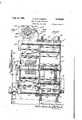
C. M CHESNEY STRIP COILING APPARATUS Filed Aug. 29,- 1942 9 Shegts-Sheet l //2 //3 6'0 6 5 INVENTOR.
' C'fzesierjlflfaa Oiczs/w,
June 12, 1945. c. M. MaCCHESIQE 2,378,024
STRIP COILING APPARATUS Filed Aug. 29, 15 12 9 Sheeiis-Sheet 2' INVENTOR.
ATTORNEYS June 12, 1945.
C. M. M C I-IESNEY STRIP COILING APPARATUS Filed Aug. 29, 1942 9 Sheets-Sheet 3 INVENTOR.
BY I
TUBA/EV? June 12, 1945. c, aCc
STRIP COILING APPARATUS Filed Afig. 29, 1942 9 Sheets-Sheetii INVENTOR. WMMQCChQS/ZQ? I HTTOEIMEYS.
n 12., c. M. MMCHESNEY I 2,378,024
STRIP CQILING APPARATUS Filed Aug. 29, 1942 9 Sheets-Sheet 6 iiillllmmlm' iiii ' INVENTOR v waste/"11111620022529 BY ATT ENEY June 12, 1945. c, M. WC'HES EY 2,378,024
STRIP COIL ING APPARATUS Filed Aug. 29, 1942- 9 Sheets-Sheet 7 /Z7 4U 40 [22 w /24 INVENTOR.
ATToEA/EYa 1 v3 me @446 J ne 12, 1945- c. M. M CHESNEY v ST Patented June 12, 1 945 UNITED STATES PATEN. OFF-ICE Chester M. MacChesney, Chicago, 111., assignor to Acme Steel Company, Chicago,'Ill., a corporation of Illinois Application August 29, 1942, Serial No. 456,657
4 Claims. ((1242-74) This invention relates to improvements in strip coiling apparatus orwinding reels and its purpose is to provide a novel and eflicient winding core having means for holding the metal strip thereon by suction so that the strip may be readily gripped and held upon coming into engagement with the core-under pressure. ,Although capable of other uses, this improved winding core, capable of automatically gripping a metal strip, lends itself to use with particular advantage in the operation of winding 9. long flat strip of steel or other strip material into the form or a succession of spiral 'coils, with no interruption of the movement of the strip between successive winding operations.
In rewinding long metal strips coming from pickling or coating baths'or other apparatus, a serious disadvantage has heretofore been presented by the necessity of stopping the movement of the metal strip when changing from one reel to another during the operation of rewinding the strip. This disadvantage is overcome by the present invention which permits a new reel to' grip the strip automatically by suction upon being brought ,into gripping position so that. the winding operation may be continued without interruption upon cutting oil the oncoming strip from the portion which has just been wound. The improved reel may also be employed with advantage in other locations where it is desired to effect quickly a positive connection between the strip and the core upon which it is to be wound,
with a minimum expenditure of time and labor.
It is, therefore, the principal object of the invention to provide a winding reel having a core equipped with suction devices adapted to grip and hold a metal strip when the strip is brought into engagement therewith under, pressure. A further object is to provide an improved winding core provided with suction cups which are capable of adjustment with respect to the surface of the core. Still another object i to provide a windmg core comprising suction cups which are resiliently mounted and are thereby capable of movement with respect to the surfaceof the core. Other objects relate 'to various features and arrartiegements which will appear more fully hereina r.
The nature of the invention'will' be understood from the following specification taken with. the accompanying drawings in which one embodiment is illustrated. In the drawings,
pable of carrying on a winding operation in a continuous process; 4 i
Fig. 2 shows an end view of the apparatus illustrated in Fi l;
Fig. 3 shows an enlarged sectional view taken on the line 33 of Fig. 2;
Fig. 4 shows an enlarged side elevation of the valve mechanism for controlling the positioning of the rotatable wheel or carrier on which the cores or winding reels are mounted;
Fig. 5 shows a sectional view taken on the irregular line 5-5 of Fig. 1;
Fig. 6 shows a sectional view taken on the line 8-8 of Fig. 1;
Fig. '7 is a detailed section taken on the line Fig. 8 is an enlarged sectional view through one Fig. 9 is a transverse sectionsthrough one of the cutter bars and its cutter, one of these cutters being mounted for movement adjacent each of the winding cores;
Fig.'10 shows'an end elevation of one of the winding cores, illustrating the mechanism by which it may be contracted to release acoil of strip material wound thereon;
Fig. 11 is an enlargement of a portion of the sectional view of Fig. 8, with the mounting of one oi. the suction cups. of the winding reel also shown in radial section;
Fig. 12 shows an axial section through one of the winding cores on the line I 2-l 2 of Fig. 8, showing-the condition of the parts when the coreis expanded;
Fig. 13 is a partial sectional view similar to.
that of Fig. 12, showing the condition or the parts of the core when it has been contracted to permit the removal of a coil of strip material;-
Fig. 14 shows an axial section through one of the friction clutches bywhich the winding cores are rotated, the section being taken on the line Fig. 15 is a perspective view of two complementary air valve members for controlling the admission of compressed air or other fluid to the cylinders by which the cutter bars are operated:
Fig. 16 shows an enlarged transverse section I through the valve mechanism which is partially illustrated in Fig. 2, showing the means by which the admission or compressed air to the supply con- Figure 1 shows a side elevation of one form .of I
strip coiling apparatus embodying the improved core of the present invention and ca.-
-duits is controlled, the section being taken on the line l6l6 of-Flg. 14; I Fig. 17 shows ase'ctional view taken on the line Fig. 18 is a sectional view taken on the line l8-l 8 of Fig. 6, illustrating the valve mechanism for controlling the admission of compressed air or the like to the cutter bar cylinders, the connections to which are in part illustrated somewhat diagrammatically;
Fig. 19 is a sectional view taken on the line l9-|9 ofFig. 1;
Fig. 20 is a somewhat diagrammatic side elevation of the principal parts of the apparatus illustrated in Fig. 1, showing the wheel or carrier on which two winding cores are mounted with one core in the upper winding position, where the metal strip being coiled is maintained under tension by a suspended tension regulator, and
} tion of both co'res;
Fig. 22 is a diagrammatic side elevation similar to that of Fig. 21, showing substantially the same relationship of'the parts except that the clutch for controlling the rotation of the wheel or carrier has been engaged to cause the carrier 3 to revolve through a half revolution and thereby reverse the positions of the winding cores;
Fig. 23 is a diagrammatic side elevation similar to those of Figs. 20 to 22, inclusive, showing the relative position of the parts after the wheel or carrier has rotated through a partial revolution, thereby bending the strip about the empty core which is moving upwardly and thus causing the strip to engage the suction cups carried by that core so that it is held in position on the core during the operation of the cutter which is then moved forward by compressed fluid to sever the strip between the wound coil and the place where it is held on the empty core;
Fig. 24 is a diagrammatic side elevation, similar to those of Figs. 20 to 23, inclusive, showing the relative position of the parts at a later stage in the rotation of the wheel where the strip has bee'n'severed adjacent the point where it is held on the empty core and the empty core and the.
' filled core are approaching the winding and un-' loading positions, respectively;
Fig. 25 is a diagrammatic side elevation, similar to those of Figs. 20 to 24, inclusive, showing the relative positions or theparts after the wheel or carrier has completed a, half revolution. thus reversing the positions of the two cores so. that the empty core occupies the winding position and begins a new coiling operation while the filled core occupies the unloading position wherein the coilmay be removed therefrom; and
Fig. 26 shows a diagrammatic plan view of the circuit connections of the cylinders, valves and "clutches which are operated by compressed air or the like to control the operation of the cutter bars, the starting and stopping of the wheel or carrier and the rotation and positioning of the wheel.
Before proceeding with a detailed description of the embodiment of the present invention which is illustrated in the drawings, reference will'be made to the principal parts of the winding apparatus with which the improved core of the present which is arranged to revolve within a stationary frame 32. The metal strip 33 which is to be wound upon the cores 3B is'withdrawn from the rolling mills, cutting apparatus or other equipment by which it is being treated, through the agency of a feeding device 34 which is driven by an electric motor 35 through a speed reducer 36. The metal strip 33 moves in the direction indicated by the arrow 31 and passes around a tensioning device 38 .which comprises a suspended wheel or roller about which the strip is looped at a point substantially below the level of the core 30 when this core is in the upper winding position shown in Figs. 1, 20, 21 and 22. The end of the metal strip is held on the upper core 30 by a series of suction cups 40 which exert a sufficient grip on the strip to maintain the end of the strip in place during the coiling operation. The tensiom'ng device 38 maintains tension in the strip within the holding ability of the suction cups and compensates for any tendency to momentary variations in the strip movement arising at the beginning of a winding operation or at other times.
The cores 3!! are power driven in the. direction indicated by the arrow 4| and a, coil of strip material is thereby formedon the upper core 30 as indicated in Fig. 20. When the formation of the coil has been carried on to the point where a lap-welded joint 42 appears above the tensioning device, as shown in Fig. 21, this will con.- stitute a signal ,to the operator to arrest the winding operation on the core which is then in the winding position and to move an empty core to that position. This is accomplished by rotating thewheel 31 in the direction of the arrow 43 through a half revolution. The rota- .tiO.'i 0f the wheel or carrier 3'] is effected by a necessary for the operator to operate a valve 45 which admits air to a cylinder 46 and thereby releases a latch member 41 by which the wheel is normally located in such a position that one of the winding cores 30 is held in the upper winding position and the other core 30 is held in the lower unloading position shown in Figs. 1, 20 and 21. The actuation of the valve 45 and the resulting movementof the latch member 41 opens another valve whichadmits air to the air clutch 44 so that the rotation 01' the wheel 31 beginsas soon as it is released by the latch member 41. After being manually opened, the valve 45 is held in open position by a latch and the rotation of the wheel 3| continues through a half revolution when this latch is automatically operated to cause the closing of the valve and the l e-engagement of the latch member 41 with a notch in the wheel.
At the same time that the operation of the apparatus reaches the condition shown in Fig. 21 and the valve 45 is operated to release the wheel and cause it to rotate through a half revolution, the rotation of the winding cores about their own axes is arrested through the engagement of the stop member 48, carried by the lower winding core, with a cutter bar 50 carried by the wheel and mounted for longitudinalmovement parallel to the axis of the core. A cutter bar 50 is associated with each core 30 and carries a rotatable cutter '51 adapted to sever the metal strip as the cutter bar is moved longitudinally throughout the ment of the stop member 48 carried by the ad- Jacent core. When this stop member engages the cutter bar a slippage occurs in the driving connection to thenotating cores through a friction driving device 52. The movement of the cutter bar in a position where it will be engaged by the stop member carried by the lower core 3' 'is effected by an air cylinder. 53 to which air is admitted when the valve 45 is actuated by the operator and the actuation of the cylinder 53 also operates a mechanical clutch 54 by which the driving connection to the lower core 30, which may have-been broken by a manual operation during the downward movement of the coil, is established at the time of the engagement of the stop member 48 with the cutter bar.
The parts of the apparatus are then in the condition shown in Fig. 22 and the wheel 3| then revolves in the direction indicated by the arrow 43 to move the two cores bodily about the axis l of the wheel as shown in Fig. 23. As this takes place, the empty core, which is still held against rotation by the adjacent cutter bar,.moves upwardly and bears against the strip 33 at such a point that the welded joint 42 is located between this empty core and the core which is occupied by the full coil of strip material. The'tensionng device 38 maintains sufllcient tension inthe portion of the strip which bears against the emptycore 30 to cause the strip to be gripped by the suction cups 40 and the parts are then in readiness for the actuation of the. cutter bar 50 associated with this core through its full cutting stroke. The bar is thus actuated at this point by an air cylinder 55 which is associated-with it and which is automatically actuated by compressed air or the like through an automatic .air valve 56 having parts which are mounted the cutting is taking place, the empty core does not rotate but both the core and the cutter move bodily with the wheel and the metal strip 33 continues to be fed to the winding apparatus through the operation of the feeding device 34.
The cutting takes place through a certain angle of movement of the wheel 3|; for example, an angle of 45 degrees as illustrated in Fig. 23; ard. as soonas the cutting is completed, the valve 56 operates to cut off the air toone end of the cutter cylinder and to admit air to the other end there'- of so that the cutter bar is automatically returned to its normal position, this return movement taking place through another angle of movement of the wheel II; for example, an angle of 35 degrees as indicated in Fig. 24. i
' Before ,the cuttingsoperation'takes place. and during the downward movement or the coil, a
'- clip "is applied to the coil of strip material on the filled reel to'prevent the material from unwinding, and this may be facilitated by throwing out the associated clutch N to'stop the rotation of the core. ,After the operator has manually actuated the clutch 54 associated with the" filled core to break the driving'connection to thiscore.
' the core may be rotated to position properly the 7 core slot 30 .so that a hook may be enteredthroughv this slot .to permit the removal of this coil of material by a hoist or the like after contracting-the core. After the strip has been-cut off, as shown in Fig.- 24, the coil of material is separatedfrom the supply and the parts are in readiness for beginning a new winding operation which is initiated as soon as the cutter bar returns to its normal position, which corresponds approximately to the completion of 'a half revolution. When the loaded core 30 reaches the unloading position shown in Fig. 25, the valve '45 m is automatically actuated by a part carried by the wheel so that the latch member 41 is'per mitted to effect an automatic positioning of the wheel and the-subp y of compressed air-to the clutch ll is cut off to arrest the operation of the driving connection to thewheel.
Of course, as soon as the air pressure is cut of! from the cylinder 55 associated with the core 30 which is moving tothe upper'winding p0sition in Fig. 24, the cutter bar is fully retracted by air pressure, controlled by the valve 56, so
g5 removes the wound coil from the core which then occupies the lower position. In this way, the feeding of the strip material is carried on continuously and the coiling of the strip is carried on without any interruption except during the limited time which is required for the movement of the wheel or carrier 3| through a half revolution. 1
Having indicated generally how a continuous winding operation may be carried out with the use of the apparatus of the present invention, the
structure of the apparatus will now be more particularly described. It includes a plurality of supporting plates 60 which are secured to the floor and which are provided with longitudinal grooves 49 80* having mounted therein a plurality of blocks 6| which'are welded to and directly support the frame 32. This frame includes a-plurality of iongltudinal frame members 83 of channel form which have their lower flanges resting directly on theblocks 6i, and a plurality of transversely exto revolve with the wheel. During the time that e tending channel members N which are welded or otherwise secured to the members 63. The blocks ii are held in adjusted position by locking members 85 which have flanges overlying their edges and these locking members are secured to the The frame structure made up of the channel beams 83 and 84 carries a pair of saddle-shaped frame members 81 comprising vertical plates 81, all of which are secured to the top flanges of two of the frame members 64, as shown in Figs. 1
m and 5. The arcuate flanges of the saddle members 81 are secured bystuds 89 to circular frame members 10 which serve as supports for the re- 'volvable wheel 3| which is mounted within them. This wheel comprises a pair of circular plates 3| as connected by an annular drum or cylinder li which is welded or otherwise secured thereto and which spaces the disks apart to form an internal chamber in which the clutches u and other parts of the mechanism are mounted. The drum ii is in recessed o'r-bowed inwardly at intervals to form pockets"3l, shown in-Fig. ,3, which are adapted to contain-the flangedcrollers II, illustrated in Figs. .3 and 19, which are spaced apart by sleeves 12 and journaled uponrods ll secured 'byset I screwsi'il in bosses 3|" formed in the disks 3].
- apertures 8| punched therein and bounded by tubular members 8 I, which form spacers for the disks 8 I.
The inner one of the two circular disks-8 I carries an annular gear 11 which is secured thereto by threaded studs 18 engaging the inwardly en-' gaging flanges 11 of the gear and threaded-apertures in the adjacent disk 8 I. The annular gear 11 is driven by a pinion 18 which is secured upon the end or an intermediate shaft 88 journaled in bearing blocks 8| fixed on the outer parts of the circular frame members 18,- as illustrated in Figs. 1 and 3. The shaft 88 has fixed thereon a double sprocket gear 82 which meshes with a double sprocket chain 88 driven by a double sprocket pinion 88 fixed upon a driving shaft 85. This shaft is journaled in bearings 86 mounted on the upper ends of frame members 81 which are in turn mounted upon longitudinal frame members 88 carried by transverse frame members 88, all of which form a part of an overhead frame structure separated from the frame 82 previously described. The shaft 85 is driven by the previously described speed reducer 88 which is also mounted upon the frame members 88. These frame members also carry a, plate 88 upon which there is mounted the previously described electri motor 85 having a shaft 85" through which the speed reducer 88 is actuated.
On the driving shaft 85, there is fixed a pinion 8I which meshes with a gear 82 secured upon a shaft 88. This shaft is journaled in bearings mounted within a tubular member 84 which is secured to the frame members 81. On the end of the shaft 88 which projects to the right, as shown in Fig. 2. beyond one of the frame members 81, there is secured a cylindrical pulley or roller 85. The gear 82 also meshes with another gear 85 which is fixed upon another shaft 81 also Journaled in bearings carried by another tubular member 84 secured to the frame members 81.
This shaft 81 has secured thereon a cylindrical pulley or roller 88 which is of substantially the same size as, and parallel to, the roller 85. The axis of the shaft 88 is located at a slightly higher elevation than the axis of the shaft 81 so that the metal strip 88, as it passes from the mills or other device by which the strip is treated, is carried over and above the roller 88 and contacts with the roller 85. After passing around the roller 85, it is carried around the roller 88 and it then passes partially around an idler roller I88 which is journaled upon a stub shaft I8I carried by the upper frame structure and projecting horizontally therefrom parallel to the shafts 88 and 81. A collar I82 secured upon the end of this shaft holds the roller I88 against endwise movement. This roller has a layer I88 of rubber'or the like forming its outer peripheral portion and it is mounted so that the metal strip 88 passing between this roller and the roller 88 contacts the surfaces of both rollers, the compressible outer layer of the roller I88 accommodating itself by its own deformation to any variations in the gauge II 2 or by applying springs thereto.
of the strip which passes between these rolls. v
The tensioning device 38, about which the strip passes in its travel from the feeding device 88 A to the winding position, comprises a cylindrical roller I I 8, shown particularly in Figs. 1 and 2, which is mounted on a shaft III carried at the outer ends of a pair of arms II2 pivoted at H8 upon the frame 82. The roller H8 is thus free to move downwardly by its own weight to maintain the strip 88 taut and this tendency may be increased by mounting weights upon the arms A pair of guide straps III, having radially extending annular flanges I I4, are secured upon the outer surface of the roll H8, being held by clamping screws II 5 engaging the projecting ears Ill thereof, These guide straps may be spaced apart to correspond with the width of the strip material 88 being coiled so that the strip is guided at in Fig. 5. Each shaft I28 has attached thereto an outwardly extending flange or enlargement I28 at its inner end which bears against the inner roller bearing unit I2I to hold the shaft against forward displacement. Cover plates I I8 are mounted over the apertures in the inner disk M in which the inner roller bearing units I2I are located. The forward portion of each shaft or trunnion is tapered as shown at I28b in Fig. 12, the tapered part connecting a larger cylindrical portion I28 with a smaller cylindrical portion I28 upon which there are mounted the hub portions of the radially extending webs I22 and I 22 of the segment I22 which constitutes a part of the cylindrical core. This segment is 'arcuate in radial cross section, as shown in Fig. 8, so that it forms a a part of the cylindrical surface of the core and it has mounted thereon the suction cups l8, previously described, which are mounted in rows both longitudinally and circumferentially of the core. The body portion of the member I22 cooperates with the complementary arcuate member I28 and I 24 to form a complete cylindrical surface when these parts are in the normal positions shown in Fig. 8. when they are contracted, v as shown in Fig. 18, they permit the removal of the coil or strip material which has been wound thereon.
Theinner web I22 of the part I22 is secured on the cylindrical part I28 of the spindle by a key I25 and a set screw I25 and this web portion has secured thereto by a stud I28 a radially extending plate I21 which is seated on the hub of the part I22 and has a radially projecting ann I21 carrying the stop member 48 previously reis adapted to receivea cutting or shearing blade I35. This shearingblade is held inthe groove I22 by a series of studs I36 which enter recesses in the blade and pass through into threaded apertures in the underlying portion of the segment I22, as illustrated in Fig. 8. The outer face of the I segment I22 is further provided with a longiferred to. This stop member is in the form of a hard metal block which is mounted in a recess I2'I in the arm I2'I, being grooved at its upper and lower edges to receive portions of the arm at the edges of the recess; Thestop member 48 is secured to the arm I21 by a stud I28. With this arrangement, the block 48 may be readily removed and replaced when desired. The body portion of the member I22 is provided with a radially extending slot I22, shown in Fig. 8, which permits tudinal inclined recess m adjacent the groove I22I whichleaves the cutting edge I35' of the cutting or shearing blade exposed in positiomto cooperate with the rotary cutting blade SI, previously referred to, which is carried at the end of the adjacent cutter bar 88. The cutter 5| is constructed in the form of an annular ring, shown particularly in Fig. 9, which is carried by .a holder I38 having an annular recess I38 in which the the insertion of a hook carried by a hoist or the like for the purpose of removing a wound coil from .the core after the core has been contracted.
The arcuate body portion of the segment I22 of the core is provided with a plurality of recesses v I22 whichare of stepped formation, being of reduced diameter at their bottoms as shown at I22. These recesses are adapted toreceive the body portions of the suction cups 48, each of which comprises a cup-shaped member I38, formed of rubber or the like, which is concaved on its outer side as shown at I38, and which has an inner body portion I38 of reduced diameter which may enter the reduced portion I22. of the recess when the cup is pressed-inwardly. The rubber member I38 is carried by a stem I3I which is provided at plementary parts. This bearing member I 48 and the holder I38 are mounted ins-slot 88' which extends inwardly from the forward end of the cutter bar 58. The holder I38 and the cutting blade I are of such dimensions that their peripheries extend beyond the walls of the\slot 5.8 to permit the rotary cutter II to cooperate with the cutting blade I38 when the cutter bar 58 is its outer end with a circular plate or flange I3I' embedded in the body portion of the member I38.
This stem has a hollow cylindrical portion which is slidably mounted in'a retaining member. I32,
constructed in the form of a hollow cylinder closed at its inner end and threaded on its outer surface to engage the threaded aperture I22 which is formed in the body portion of the segment I22 centrally of the bottom portion I22 of the recess.
'The retaining member is provided at its inner end with a slot l 32' adapted to be engaged by a screwretaining member in the segment I22 andafter the adjustment has been made the retaining driver or the like for adjusting the position of the member may be held in adjusted position by a lock nut I83. After the stem I3I hasbeen' inserted in the cylinder of the retaining member, the
outer end of this retaining member is bent inwardly as shownat I32" to conform to the curved contour of the outer portion'of the stem, thus limiting the outward movement of the stem imder th influence of a coil spring I84 which is mounted in the cylinder. In this way the cups 48' are all resiliently mounted and when the metal strip 33 is pressed against them they are adapted to move inwardly and tobe'flattened' out on their outer faces so thata suction is set up and the cups maintain a firm grip on the metal strip. The retaining members may be adjusted to position the suction cups lmiformly and to suit the gauge and flexibility of the metal strip and the tension exerted thereon so that each cup will maintain a firm grip on the end portion of the strip.
" At the forward edge of the series'oi suction cups; having in mind the direction of rotation indicatedby the arrows 4|, the segment. I22 of each core is provided with a longitudinally extending groove I22 of rectangular cross. section which moved forwardly in the manner hereinafter more particularly described. The bearing member I48 is secured within the slot 58' by a pin I-4'I which fits within a transverse aperture 58 formed in the cutterbar. This pin has a head I4I' provided with an annular inclined face adapted to"- be engaged by a'set screw I42 which is mounted within an inclined threaded aperture .58 formed in the cutter bar. The parts of the bearing member I48 are spaced slightly to provide a radial passageI48' which permits lubricant to pass between the raceways of the ball bearings I38 and also to lubricate the surfaces of the pin I4I. The segment I23 is provided toward itsends' 'with inwardly extending flanges which carry pairs of spaced ears I23 which extend on opposite sides or two inwardly extending ears I22 which are formed on the segment I22. These ears are provided with registering apertures which are engaged by pivot pins I44, the pins being secured in the inner ears I22 so that the,
segment I23 is thus mounted for, pivotal movement with respect to the segment I 22. In a. similar manner, the segment I24 is provided withinlongitudinal edges of the segment I22 andv wherein they cooperate with the member I22 to l8 wardly extending flanges provided with spaced .pairs of ears I24 which receive between them other cars I22 which. are formed'on the member I22. These registering pairs of ears are engaged by pivot pins I43 which are secured in the inner ears I22 so that the segment I24 is thus I mountedfor pivotal movement with respect to the segment I22.
The two segments I23 and I24 are provided at their edges opposite the pivots I44 and I4! with v circumferentially extending teeth I23" and I24 i which intermesh slightly with each other whenthe segments I23and I24 are pivoted outwardly to their normal positions,-as shown in Fig., ,8,.
wherein their edge surfaces abut against'the form a complete cylinder. When the segments are pivoted inwardly to contract the core, as shown in Fig. 10, these teeth I23 and I24 intermesh wit each other to a greater extent and limit the ward swinging of the two movable segments. v
The relative pivotal movement of the segments I23 and I24 m further limited, adjacent their free edges, by pins I46 which are mounted in sockets formed in the inner end portions of these segments and which engage slots I21 formed in the plate I21 attached to the intermediate segment I22. These slots I21 are elongated, as shown in Figs. 8 and 12, and, when these pins are in the outer ends of these slots, the segments I23 and I24 will be in their expanded positions, shown in Fig. 8, wherein the core has a cylindrical form. When the pins I46 occupy the inner ends of these slots, the core will be contracted to permit the removal of the coil of material wound thereon.
The pivotal movement of the segment I23 and I24 is effected by toggle mechanism operated by a crank handle I50. This crank handle is secured upon the end of a shaft II which is journaled in bushings I52 mounted in the bosses I24 formed on the pivotal segment I24, as illustrated in Fig. 12. The crank handle I50 is formed integrally with an arm I53 extending radially from the shaft I5I and another such arm I53 is secured on the shaft at the other side of the adjacent bushing I52. These arms receive between them the end of a link I54 which is pivoted to the arms I53 by a pin I55. The other endof the link I54 extends between a pair of cars or bosses I23 which are formed on the inner side of the other pivoted segment I23 and this link is connected to these cars or bosses I23 by a pivot pin I56. Similarly, at the inner end of the shaft I5I, another pair of arms I53 are secured on the shaft and are pivotally connected by a pin I55 with a link I54 which is connected by .a. pivot pin I56 with other ears I23 carried by the inner side of the segment I23 adjacent its free edge.
With the foregoing arrangement, it will be apparent that when the arms I53 and the links I54 substantially align with each other, as shown in Fig. 8, the Segments I23 and I24 will be in their expanded positions. As a matter of fact, thepivot pins I55 should swing slightly beyond a plane passing through the axis of the shaft I5I and the pins I56 when the segments are in this expanded condition and in order. to insure this result when thelinks are actuated by turning the shaft. I5I-tlirough the agency of the crank handie :50, set screws I51 are mounted in bosses 1w carried by the links I54 and arranged to engage the teeth I23 of the segment I23 when the core is expanded. These set screws may be adjusted to secure any desired operation of thetoggle formed by. the arms I53 and the links I54 and they may be secured in adjusted position by the lock nuts I56. When the crank handle is swung toward the left, as viewed in Fig. 8, the parts assume the relative positions shown in Fig; 10, where the segments I23 and I24 are swung inwardly. In order that the segments may be located in either position, the radial portion I22 of the intermediate segment I22 of the core is provided with an arm I22 which projects in a radial plane, as shown in Fig. 8, and this arm is tures in the'outer faces of the arm I22, as shown at I60, and they are normally forced outwardly by coil springs I6I. The pivot pin I55 which connects the arms I53 and the link I54 at the inner end of the core, is provided with an enlarged head I55 having a cone-shaped reces I55 therein which is adapted to be engaged by the pointed extremity of either one 'of'the pins I60. These pins are so positioned that when the segments I23 and I24 are contacted, as shown in Fig. 10, the innermost pin I60 will automatically slide over the rounded head I55 of the pin and engage the recess I55, thus holding the segments in the contracted position. When the crank handle I50 is operated to expand the segments, the outermost pin I60 will, in a similar manner, move into automatic engagement with the socket of the pin I55 and thus hold the segments I23 and I24 in their expanded position.
It will, of course, be apparent that the segments are also held in their expanded position by the toggle action of the arms I53 and the links I54. Having ,described the means for contracting the cores 30 to permit the removal of a coil of wound material, reference will now be made to the meansfor rotating these cores during. the
winding operation. Referring to Fig, 5, it will be seen that each shaft I of a winding core has mounted thereon one of the friction clutches 54 previously referred to and that each clutch includes a cup-shaped clutch member I65 which has its hub portion I65 rotatably mounted but fixed against endwise movement upon a portion I20 of the shaft. This hub portion has secured thereto a sprocket gear I66 adapted to be driven by a sprocket chain I61 in the manner hereinafter described. 'The clutch member I65 has secured thereto around its outer periphery an inwardly extendingv flange I65 which may be faced with leather or other non-metallic material'and ment with the flange I65 to press this flange which extends on the outer side of the radiating annular flange 168* of a clutch member I66 which is spllned upon the shaft I20 for longitudinal movement thereon. This clutch member I66 has mounted thereon a movable annular shoe I66 which'is adapted to be moved into engageagainst'the flange I68- and thus form a driving provided with an annular provided with cylindrical bores I22 in which are connection between the two complementary clutch members I65 and I60, thereby causing the shaft I20 to be driven through the agency of the sprocket chain I61.
The clutch shoe I68 is connected through a series of links I63 with aseries of small levers I10 which are pivoted upon a ring "I having threaded engagement with the cylindrical body portion of the member I68. The levers I10 are pivoted at their intermediate points on the member Ill and their ends opposite the pivotally connected links I69 are in turn pivotally con with other links I12 which have their op-' nected posite ends pivotally connected with ears I12! projecting outwardly from the clutch ring I13. This clutch ring is splined on the shaft and is groove I13 engaged by clutch actuating pins I14 which are carried by a clutch actuating lever I15. This lever has a part I15 which and which has mounted therein the pins I14. At its intermediate point, this clutch lever n5 is pivoted on brackets I16 which are carried by the inner disk 3| of the wheelor carrier 3|. At
one end, each clutch operating lever I15 is pivotally connected to an actuating rod I11 which extends axially of the wheel and through an aperture 3" in the front disk '3I'f thereof, adjacent surrounds the ditch ring I13 bracket i11 as shown in Figs. 3 and 5. The
rod I11 provided on the front side of the wheel with a needle I11 by which it may be manipulated to effect longitudinal movement of the clutch ring I13 on the shaft and thereby shift the member I68 to eng e or disengage the fric tion ring I65 and thus make or break a driving connection between the shaft and the clutch member I65. At its other end, each clutch actuating lever I15 is pivotally connected to a link I18 which is in turn pivotally connected to another actuating rod I18. These rods I18. are mounted to slide in sleeves I88 which are fixed upon and extend inwardly or rearwardly from the rear disk 31''- of the wheel. Each rod I18 is adapted to be actuated by a shoe I8I which is in turn operated/when the associated cutter bar 58 is moved outwardly to engage one of the stops 48 and thereby arrest the rotation of the reel.
As shown' particularly in Fig. 3, the endless. sprocket chain I61, which rotates the clutchmemher I65, is arranged to mesh with andextend around a part of the peripheral portion of a sprocket pinion I84 which is secured upon a central driving shaft I85. The shaft I85 is mounted in alignment with another shaft I81 to which it is connected through the friction driving device 52 previously described. The shaft I81 is 'journaled in a bearing block I88 carried by the portion I88 of the frame structure and, at the rear of the bearing block I88, the shaft I81 hassplined thereon a sprocket gear I88. This sprocket gear is maintained against endwise displacement by a notched plate I8I and it is driven, as shown in Fig. 2, by a sprocket chain I82 which passes around a sprocket pinion I88 fixed upon the projecting end of the mainshaft of the gear reducer 36, this being the shaft upon whichthe driving pinion 8| is also secured. By this-arrangement, a continuous driving force may be applied from with the cutter bar.
Each cutter bar has secured thereon at its rear end a transversely extending bracket 286 which is bifurcated at its inner extremity to embrace a disk 281 secured upon the end of a piston rod 288. The bracket 286 has a tooth 286 engaging the annular groove 281* formed in the disk'so that a driving connection is formedbetween the bracket andthe piston rod without interfering with the free movement of the piston rod. This piston rod is connected at its other end to a piston 288 which is mounted to reciprocate in a cylinder 2I8. The cylinder heads 2I8 and 2I8 of each cylinder are mounted in the rear and front disks of the wheel 3|, respectively', and a fluid tight joint is formed around each piston rod 288by a packing chambenand a packing gland 2| I.- Air isadapted to be admitted to the left-hand end of each cylinder, as viewed in Fig. 6, through a pipe 2I2, thus causing the piston 288 toexecute a forward stroke and thereby move the cutter bar transversely'to the strip 38, being wound and cutting off this strip in the manner previously referred to. After the cutting operation has been completed, compressed air or other fluid is adapted to be admitted tothe other Y end of the cylinder through a. pipe 2I8, wherethe gear reducer through the sprocket chain and the connected shafts to the sprocket chain I61 by which the clutch members I65 are rotated,- except as slippage may be permitted by the friction driving device 52 which is illustrated inFigs. 2, 3, 5 and 14.
Having described the means for rotating the cores 88, reference will now be made to the means for actuating the cutter bars 58 to control the rotation of the cores and to effect the cutting of the strips after a full coil has been formed on one of the cores.- These cutter bars 58, which have the cutters 5I mounted in their forward ends in,
the manner heretofore described, are carried by the wheel 3| in the manner shown particularly in Figs. 6 and 1 where it will be seen that each cutter bar is adapted to be projected through an aperture 3 I formed in the front disk I I of the wheel or carrier while the intermediate portion of the cutter bar is journaled in a bearing member- 285 carried by the rear disk ll of the wheel. Each cutter bar 58 is supported at its forward end by a .pair of blocks 244 having bevelled edges which flt into longitudinal grooves 58 in opposite sides of the cutter bar. The upper wall of each groove is inclined to flt the bevel of the supporting block and the blocks 244 are secured by screws 245 to the opposite ends of a semi-circular bracket 246 secured on the front wall 3| of the wheel 8|. One block 244 is slotted for engagement by its each other-to cause their outer arcuate surfaces to fit closely against the inner annular surface screw 245 and anadjusting screw 241, mounted in the bracket, engages this block so thatthe spaced relation of the two supporting blocks may be regulated to secure the desired engagement upon the plston'executes a reverse 'strokeand retumstha cutter to its normal position shown in Fla. 6. I x x The admission'of compressed air or the like to the, cylinders in is controled by the automatic valve 56 previously referre to which is actuated by the rotation of the wheel or carrier 8|. I valve mechanism is shown particularly in mac, 6, l3, 16, 1'1 and 18, where it is shown as comprising complementary blocks 215' and '2I5 which are provided on their inner sides with complementary semi-circular recesses so thatthey conform to and fit over a portion of the. shaft I81 between the friction driving device 52 and the bearing blocks I88. These blocks 2|! sockets adapted to receive coil springs 216' by which the blocksare normally pressed awayv from of the surrounding valve sleeve 2I1. This sleeve 2I1 is provided with two ports 2 I1 and two ports 2I1 in which are connected the nipples at the ends of the pipes 2I2 and2l3, respectively, so
that communications are thus established-with the cylinders by which the cutter bars 58- are 4 operated.
The sleeve-2H which is thus connected to the pipes'2l2 and 2I'8 is adapted to rotate with the wheel orcarrier II but the inner valve blocks 2 I 5' and 2 I! are adapted to be held against rotation on the shaft I81. For this purpose, the
block 2I5 has attached thereto or formed integrally therewith alaterally projecting sleeve 2I8 in which the shaft I81 is joumaled and this sleeve is provided with a portion 2I8 of reduced diameter which has clamped thereon, by means of the cap screw 2", a plate 228 shown. in Fig. I 11, which extends downwardly and is attached to the upright frame structure'bebw the bearing member l88, as shown in Fig.6. 'Each ofthe valve blocks 2I5 and H5" is provided with a longitudinally extendin passage 2I6 arranged to communicate with a chamber 2I5 which opens through the periphery of the valve block. These chambers 2" are located diametrically opposite to each other, as shown in Fig. 16, and they communicate-with the'SuDPW-mm d 223, shown in Figs. 6, 14 and 17, through which compressed air or the like is supplied to the control valve. The two chambers 2l5' are offset longitudinally of the shaft I81 and the ports 2" which communicate with the pipes 2l2 are similarly offset longitudinally of the shaft with respect to the ports 2ll which communicate with the pipes 213. The pipe 222 thus is arranged to supply compressed fluid to the pipes 2l2 while the other pipe 223 is arranged to supply the pipes 213.
Assuming that the wheel 3! and the valve sleeve 2" are in such positions that the pipe 2I2 leading to the upper cylinder 2") is in communication with one of the chambers 2!! through which compressed air is supplied from the pipe 222, the compressed air will then flow to the left-hand end of the upper cylinder, as viewed in Figs. 7 and 18, thereby causing the piston 209 in that cylinder to execute a forward stroke and to cause a corresponding forward stroke of the connected cutter bar 50. During the forward stroke the air in the cylinder at the other side of the piston will be exhausted through the connected pipe-2B, the air passing 4 from this pipe through the port 2|! and thence outwardly through a groove 2|! which is formed in the block 245 and which communicates with an exhaust passage 224 located between the inner wall of the sleeve 2H and the fiat faces Hi of the valve bloclm which are then in the upper position, these blocks being flattened on opposite sides for this purpose. Immediately after this forward stroke of the cutter bar has been executed, the pipe 2|5 which has'been supplying air for causing that forward stroke will pass out of communication with the chamber 2|5 shown at the left in Fig. 16, and the port 215" which communicates with the pipe 2|: associated with that cylinder will then pass into communication with the chamber 2H of the other valve block 2N". Thereupon, the compressed air passing through the pipe 2l3 will cause the piston to execute a return stroke during which the air in the cylinder which has previously been supplied through-the pipe 2l2 will be exhausted through that pipe and through a groove 2l5' which is formed in the valve block 2l5' to communicate with the previously described exhaust passage 224. shown in the lower position in Fig. 6, reaches the upper position in which the cutter bar is to be actuated, the operations which have just been described will be repeated, the air being supplied to and exhausted from the cylinder through the other pair of pipes H2 and 2". In this way,
the cylinders which actuate the cutter bars are operated automatically at predetermined points in the cycle of operation of the wheel or carrier 3| and by suitably locating the ports 2" and 2"", as well' as the chambers 2l5 and the grooves H5 and 2L5,- the points at which the cutter bars are actuated and the part of the rotation of the carrier 3| through which the movement of the cutter bar takes place may be regulated as desired.
In addition to the forward and reverse strokes of the cutter bars 50 which are effected by com-' pressed air or the like in the cylinders 269, as just described, there is the initial movement of I the cutter bar, previously referred to," for projectlng the end of each cutter bar into the path of one of the stops 48 carried by a core 20, when the core is in its lower position, for the purpose of arresting the rotation of the core and holding When the other cylinder 2lll, which is bit it against rotation during its subsequent upward swing when its suction cups are brought into engagement with the strip. This is accomplished by the shoe I81, previously referred to, which is arranged to be actuated by compressed air or the like in the cylinder 53, as shown in Figs. 5, '7 and 26. This shoe is located to be in alignment with a cutter bar 50 when the cutter bar is in'its lower position with the rotation of the wheel 3| arrested and the shoe also aligns with the rod 119 by which the clutch 54 in the driving connection to the lowermost core 30 is operated, so that when the shoe is forced toward the right, as viewed in Figs. 5 and '7, it will operate to engage the clutch members of the associated clutch 54 and also to push the cutter bar in a forward direction to an extent sufiicient to bring it into line with the stop 48 carried by the adjacent core 30 so that the rotation of the core is positively stopped at a predetermined point in its cycle. The shoe H which efl'ects theseoperations is mounted upon the end of a piston rod 225 which is arranged to reciprocate through the end wall of the previously described cylinder 53 to which compressed air is supplied through a pipe 228. A piston 22! is mounted on the rod 225 in this cylinder and, when compressed air is admitted through the pipe 226, the piston moves toward the right against the compression of the coil spring 228, mounted in the cylinder, thus moving the clutch operating rod I19 and the cutter bar 50 in a forward direction. During this time, the piston 20!! in the connected cylinder 2N will move in a forward direction to the same extent that the cutter bar is moved; as illustrated by dotted lines in Fig. 6 and, to permit the exhaust of the air in the right-hand portion of the cylinder through the connected pipe M3, at this time, the valve block 2|5 is provided with a laterally extending passage 2l5 shown particularly in Figs. 15 and 16, which will then communicate with the port leading to the connected pipe 243 through which the air may be exhausted to the extent necessary to allow the desired limited forward movement of the piston and of the cutter bar. bar has been effected, to bring it into the path of the stop 48 on the core, the shoe l8] and the piston 221 will be automatically returned to their normal positions by the coil spring 228 when the valve is again closed.
The latch member 41, which stops and positions the wheel or carrier 3| with one core in the upper winding position andthe other core in the lower unloading position, is positioned on the frame adjacent the bottom of the wheel, as shown in Fig. 2, and is illustrated diagrammatically in Fig. 26. This latch member is normally actuated in a forward direction by a coil spring 2 30 andbears against the side face of the annular gear 11 by which the wheel or carrier ll is rotated. When the carrier reaches the proper position with one core 30 in the lower unloading position and the other core 30 in the upper winding position, the spring 230 operates automatically to force 'the end of the latch member '41 into engagement with one of two diametrically opposite notches 11 in the side face of the gear, thus bringing the wheel 3| to rest. At the same time that this occurs, one end of the notch 41 in the latch member 41 will engage the handle 23! of the air clutch valve 2 by which the flow of compressed air to the air clutch 44 a through the pipe 232 is controlled, thus closing When this forward motion of the cutter.
clutch 44 to be deflated, thereby arresting the driving connection to the wheel.
The rotation of the wheel 31 1s initiated, as-
previously stated, by the operator, who opens the latch valve 45 'to retract the bolt 41 and admit air to the clutch 44 when he observes a welded Joint in thestrip approaching the wound strip,
as shown in Fig. 21. The opening of this valve starts the rotation of .the wheel and also causes the flow of compressed air through the pipe 233 and the branch pipes 225'and 234 to the cylinders 53 and 46, respectively,'thereby opening the valve 23I and engaging the clutch 54 of I the lower cylinder as described above This latch valve 45 is shown somewhat diagrammatically in Fig. 26 and is illustrated in greater detail in Fig. 4; It comprises a collar 235 fixed upon the air supply pipe 233 ,and having an outwardly extending flange engaged by one end of a coil. spring 235 which surrounds thepipe and a portion of the collar and which is engaged at its other end by a valve operating sleeve 231 having an annular groove 231 engaged by pins in the opposite arms of a bifurcated operating'lever 238. This lever is pivoted at 239 on a bracket 240 which is is pivoted at 242 on one of the supporting rings or the frame structure within which the wheel rotates. This trip lever 24l is of bell crank form,
having a transverse extremity 24l which is adapted to .enter the-annular groove 231 when the collar 231 has been elevated by the handle 238. to hold the valve in'open position. The trip lever 2" also has a transverselyextending arm 24! which is located in the path oftravel of each' of two diametrically opposite lugs 3| carrledby the wheel 3|. As the wheel reaches the position where its rotation is arrested by the engagement of the locking member 41 with the notch 11 'in the ring gear 11, with a resulting closing of-the valve 23l, one of the lugs 3| engages and trips the lever 24!, thus releasing the sleeve 231 and causing the valve 45 to be closed by the spring 235. shuts oft the flow of compressed air through the pipes 233 and 225' to the cylinder 53, and also shuts oil the flow of air to the cylinder 45, so that the pistons in these cylinders are then retracted by the associated springs, leaving the clutch 54 of the lower core 30 engaged and leaving the lower cutter bar 50 advanced into the path of the stop 48 carried by the lower core. The lower core is then held against rotation by the adjacent cutter bar but the driving connection to this core is established and the slippage the winding operation as soon as the strip has been cut oil! and the associated cutter bar has been withdrawn, it will be understood that the clutch 54 associated with this core may be manually opened'by manipulation of the rod I11 and the handle I11 for the purpose of rotating the core until the'slot 30, shown in Fig. .25, is in the [proper position to'receive the hook, carried by The closing of this valve in the driving device '52 takes place until the wheel 31 again rotates and the core in the lower position-moves upwardly into engagement with the strip, as shown-in Fig. 23. In this way, the
core'is held against rotation while the suction .cups carried thereby operate togrip the strip. This core continues to be held against rotation until after the associated cutter bar has been.
Although the driving clutch 54 or the core 30 which moves upwardly from the unloading posi- 7 tion to the winding position is engaged automatically before that movement begins, as stated in the preceding paragraph, in order to insure that 'a crane or hoist, by which the coil of strip material is removed from the core when the core is in an unloading position. After the rotation of the filled core has thus been stopped, the handle I50 may be manipulated to contract the core. and thereby facilitate theremoval oi the coil.
From the foregoing description, it will be ap-- for the very brief and temporary interruption which takes place when the two cores are being reversed in position and the stripis being cut off by the action of one of the cutter bars, During the winding operation, the wheel'3l-is stationary, as shown in Fig. 20, and the strip material is wound upon the core in the upper position while the lower core is held stationary in the lower unloading position. When the operator Observes the welded joint 42 in the moving strip appear in proximity to the outer margin of the coil of material being wound, as illustrated in Fig. 21, that is a signal to him that the coil is complete and he then manually actuates the operating valve 45 to admit compressed air to the cylinder 45 which operates through the piston 243 to retract the nection is established to the wheel which then rotates'to move the coil of material from the winding position to the unloading position. At the same time that the cylinder 45 is actuated to retract the bar 41, compressed air is admitted to I the cylinder" 53, there actuating the shoe Ill through the piston 221 so that the cutter bar 50 which is then in thelower position is moved forwardly into the path of the stop 48 carried by the lower core 30 and the bar I13 associated with the lower core is actuated to close the driving clutch 54 of that core. The'parts are then in the condition shown in Fig. 22 and, as the wheel rotates, the .coil oi material assumes a midposition,,shown in Fig 23, where a clip 51 is applied to the outer layers of the coil to prevent the unwinding thereof when the outer layer is subsequently cut off from the source of supply and. at the same time, the core 30 which has been in the lower position moves upwardly and reaches a position where the rotating wheel actuates the control valve 55 to cause the proper sequence of movements of the pistoninthe cylinder 55 associatedwith that core. The cutter bar then moves forwardly through its cutting strokethrough a certain angle of movement of the wheel, as illustrated in- Fig. 23, with the strip of material being bent around the empty core as there illustrated-and with the supply portion of the strip gripped by the suction cupson the empty core. As .the motionoi'the wheel continues, the v stage is reached where the parts occupy the relative positions shown in Fig. 24 where the cutter bar is retracted during a certain part of the angular movement and the full core approaches the lower position. Before the lower position is reached, as shown in Fig. 25, the valve ll is automatically closed by the engagement with the latch member 2 of oneol the lugs 3i carried by the wheel so that the valve 45 is automatically closed by its spring,thereby shutting oil the flow of compressed air to the cylinders 38 and 53,-
allowing the shoe l8lto be retracted by its associated spring 228 and permitting the bar 41 to be moved against the race of the gear 11 by its spring 230. The bar 41 then snaps into engagement with another notch 11' of the gear to arrest the rotation or the wheel and the driving connection is at the same time broken by the deflation of the expansible member I01 of the air clutch M. The coil 01' material may then be removed from the full reel in the lower position, manually manip-' ulating the associated clutch M, if necessary, to get the core into the right-angular position for connection with the hoist. At the same time that this occurs, the empty core having the end of the strip attached thereto reaches the upper winding position and its rotation immediately begins because the driving connection has previously been established by the closing of its associated clutch it and the rotationstarte as soon as the associated cutter bar it is withdrawn.
1. Apparatus for winding metal strip material, comprising a rotatable cylindrical core, and suction cups carried by the periphery oi said core for engaging and holding a metal strip upon contact with said strip under pressure.
' 2. Apparatus for winding metal strip material comprising a rotatable cylindrical core, and suction cups carried by the periphery of said core for engaging and holding a metal strip upon contact with said strip under pressure, and means for adjusting the positions or said cups with respect to the surface of said core.
3. Apparatus for winding metal strip material comprising a cylindrical core having a plurality of resiliently mounted suction cups adapted to engage and hold a metal strip coming intmengagement with said core.
4. Apparatus for winding metal strip material comprising a cylindrical core having a plurality of resiliently mounted suction cups adapted to engage and hold a metal strip coming into engagement with said core, and means for adjusting the mountings of said suction cups to vary the positlons of their strip engaging portions.
CHESTER. M. MACCHESNEYI'.
Priority Applications (1)
| Application Number | Priority Date | Filing Date | Title |
|---|---|---|---|
| US456657A US2378024A (en) | 1942-08-29 | 1942-08-29 | Strip coiling apparatus |
Applications Claiming Priority (1)
| Application Number | Priority Date | Filing Date | Title |
|---|---|---|---|
| US456657A US2378024A (en) | 1942-08-29 | 1942-08-29 | Strip coiling apparatus |
Publications (1)
| Publication Number | Publication Date |
|---|---|
| US2378024A true US2378024A (en) | 1945-06-12 |
Family
ID=23813621
Family Applications (1)
| Application Number | Title | Priority Date | Filing Date |
|---|---|---|---|
| US456657A Expired - Lifetime US2378024A (en) | 1942-08-29 | 1942-08-29 | Strip coiling apparatus |
Country Status (1)
| Country | Link |
|---|---|
| US (1) | US2378024A (en) |
Cited By (12)
| Publication number | Priority date | Publication date | Assignee | Title |
|---|---|---|---|---|
| US2537588A (en) * | 1946-08-27 | 1951-01-09 | Eddystone Machinery & Mill Sup | Web winder |
| US2620141A (en) * | 1946-04-05 | 1952-12-02 | Langbo Georg | Winding machine for paper rolls |
| US2779547A (en) * | 1953-07-14 | 1957-01-29 | Bowaters Dev & Res Ltd | Winding mandrel with suction means |
| US2973160A (en) * | 1959-01-26 | 1961-02-28 | Mercury Engineering Corp | Expandable mandrel for web rewinders |
| US3126165A (en) * | 1961-01-31 | 1964-03-24 | Jan van euk | |
| US3127122A (en) * | 1961-04-20 | 1964-03-31 | Rewinding mechanism for printing machines | |
| DE1237050B (en) * | 1959-02-03 | 1967-03-23 | United States Steel Corp | Continuously working multi-drum reel for stiff metal strip |
| DE1291967B (en) * | 1963-05-11 | 1969-04-03 | Properzi Ilario | Device for winding a continuously emerging metal strip |
| DE1499086B1 (en) * | 1964-02-05 | 1970-01-02 | Du Pont | Apparatus for winding the leading end of a moving web |
| US4327876A (en) * | 1980-10-02 | 1982-05-04 | William T. Kuhn | Continuous center-winding apparatus and method |
| US5797559A (en) * | 1996-09-18 | 1998-08-25 | Ncr Corporation | Winding arbor having a plurality of air valves for making coreless paper rolls and method for using |
| US5964430A (en) * | 1998-05-28 | 1999-10-12 | Ncr Corporation | Winding arbor |
-
1942
- 1942-08-29 US US456657A patent/US2378024A/en not_active Expired - Lifetime
Cited By (13)
| Publication number | Priority date | Publication date | Assignee | Title |
|---|---|---|---|---|
| US2620141A (en) * | 1946-04-05 | 1952-12-02 | Langbo Georg | Winding machine for paper rolls |
| US2537588A (en) * | 1946-08-27 | 1951-01-09 | Eddystone Machinery & Mill Sup | Web winder |
| US2779547A (en) * | 1953-07-14 | 1957-01-29 | Bowaters Dev & Res Ltd | Winding mandrel with suction means |
| US2973160A (en) * | 1959-01-26 | 1961-02-28 | Mercury Engineering Corp | Expandable mandrel for web rewinders |
| DE1237050B (en) * | 1959-02-03 | 1967-03-23 | United States Steel Corp | Continuously working multi-drum reel for stiff metal strip |
| US3126165A (en) * | 1961-01-31 | 1964-03-24 | Jan van euk | |
| US3127122A (en) * | 1961-04-20 | 1964-03-31 | Rewinding mechanism for printing machines | |
| DE1241225B (en) * | 1961-04-20 | 1967-05-24 | Dick Co Ab | Winding device |
| DE1291967B (en) * | 1963-05-11 | 1969-04-03 | Properzi Ilario | Device for winding a continuously emerging metal strip |
| DE1499086B1 (en) * | 1964-02-05 | 1970-01-02 | Du Pont | Apparatus for winding the leading end of a moving web |
| US4327876A (en) * | 1980-10-02 | 1982-05-04 | William T. Kuhn | Continuous center-winding apparatus and method |
| US5797559A (en) * | 1996-09-18 | 1998-08-25 | Ncr Corporation | Winding arbor having a plurality of air valves for making coreless paper rolls and method for using |
| US5964430A (en) * | 1998-05-28 | 1999-10-12 | Ncr Corporation | Winding arbor |
Similar Documents
| Publication | Publication Date | Title |
|---|---|---|
| US2378024A (en) | Strip coiling apparatus | |
| US3727853A (en) | Film winding machine | |
| US2671495A (en) | Apparatus for storing and feeding web material | |
| EP0026498A1 (en) | Improvements to the apparatuses for applying elastomeric fillers to tire bead cores | |
| US3421709A (en) | Rewinding machines | |
| US1982610A (en) | Hose reel | |
| US3044431A (en) | Internal pipe clamp | |
| US2343747A (en) | Machine for making tubular structures | |
| US2416523A (en) | Expansible band-building drum | |
| US3221641A (en) | Bundling machine | |
| US2268125A (en) | Coiler | |
| US2475480A (en) | Paper winding machine | |
| US2247004A (en) | Driving mechanism for flexible shafts | |
| US2812910A (en) | Double drum winding machine and flying winding roll changer | |
| US3796389A (en) | Winding apparatus for thin band plates | |
| US2785750A (en) | Ring gasket cutting machine | |
| US2520826A (en) | Means for preventing deformation of tubular cores | |
| US3670979A (en) | Web handling apparatus and spindle chuck therefor | |
| US4484714A (en) | Beam mounted core enveloper | |
| KR100200163B1 (en) | Machine and process for coiling and winding tubular sleeves in elastomeric material incorporating reinforcing fibers | |
| US2197747A (en) | Multiple yarn package holder | |
| US3191883A (en) | Winder for web material | |
| JPH04239428A (en) | Replacing device for strip material roll | |
| US1881706A (en) | Apparatus for handling articles | |
| US1645239A (en) | Apparatus for the manufacture of pipes and the like from metal sheets or plates |