US2376103A - Cigarette-making machine - Google Patents
Cigarette-making machine Download PDFInfo
- Publication number
- US2376103A US2376103A US463124A US46312442A US2376103A US 2376103 A US2376103 A US 2376103A US 463124 A US463124 A US 463124A US 46312442 A US46312442 A US 46312442A US 2376103 A US2376103 A US 2376103A
- Authority
- US
- United States
- Prior art keywords
- plate
- cigarette
- paper
- crank
- tobacco
- Prior art date
- Legal status (The legal status is an assumption and is not a legal conclusion. Google has not performed a legal analysis and makes no representation as to the accuracy of the status listed.)
- Expired - Lifetime
Links
Images


Classifications
-
- A—HUMAN NECESSITIES
- A24—TOBACCO; CIGARS; CIGARETTES; SIMULATED SMOKING DEVICES; SMOKERS' REQUISITES
- A24C—MACHINES FOR MAKING CIGARS OR CIGARETTES
- A24C5/00—Making cigarettes; Making tipping materials for, or attaching filters or mouthpieces to, cigars or cigarettes
- A24C5/08—Machines with aprons and tables for wrapping
Definitions
- This invention relates to cigarette making machines and more particularly to a machine of this character for making cigarettes in comparatively small quantities for immediate use.
- One of the important aims of the instant invention is the provision of a small, compact 1 and sturdily built machine that is fully capable of delivering therefrom perfectly rclled cig arettes as long as a supply of paper and tobacco is maintained in-the machine.
- a further aim of the invention is to provide a machine requiring a minimum am'ount of mam; ual manipulation for rolling a cigarette.
- a yet'further aim of this invention is the provision of a cigarette making machine wherein the mechanism for carrying out the severalflsteps necessary to roll a cigarette is so arranged'and related that substantially uniform power is" required throughout a complete tion of the machine.
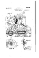
- Fig.1 is aperspective view ofa cigarette making machine constructed in'accordance with this invention.--
- Fig. 2 is a front elevational view of themachine with the end and cover member s together with the receiving tray removed therefrom to better disclose the operating mechanism.
- Fig.3 is an elevational view of-the crank side of the cigarette making machine, the parts being shown in position assumed at the beginning of the operation for forming a cigarette.
- I Fig. 41 s a top plan view of the machine with the endand cover members removed.
- Fig-5 is a bottom plan view.
- Fig.6 is an elevational viewof the machine opposite the crank.
- Fig. 7 is a cross section on the line VII'-VII of Fig. 2 with the parts in the same position as shown in the preceding figures; 7 r
- Fig. 8 is a similar section with the parts in slightly advanced position frorn that shown in Fig. 7. I
- Fig. 9 is a like section with the parts in the position assumed immediately afterthe knife has cut the paper for a cigarette.
- Fig. 10 is a cross section on the same line as Fig, 7, showing a cigarette rolled a1mostto'com'-- pletion.
- v Fig. 11 is a fragmentary section taken on line Xmxrorr'iea I I I I
- Fig. 12 is a fragmentary elevational view of cycle of operaside of the having threaded end sockets aligned withopen ings 28 (Fig. 5) in the side plates for receiving the arrows.
- Fig. 13 is a sectional view taken. on line XIII-XIII of Fig. 4 looking in the direction of Fig. '14. is a. fragmentary section XIVXIV of Fig. 9.
- Fig. 15 is a cross section of the paper feeding mechanism taken on line XV-XV of Fig. 8.
- Fig. 16 is a side elevational view of a knife control arm.
- Fig. 17 is a vertical section on the same line as Fig. 21 is a fragmentary perspective view ofthe crank. 7
- numerals 22 and 24 designate side plates held in fixed spaced relation by a'plurality of spacers 26 screws 30' which are provided with elongated heads 3
- a plurality of cross plates in addition to their primary function, further assist in retaining plates/22 and 24 in fixed spaced relation and in elude parallel, vertically disposed hopper plates 32, a bottom plate 34 for the hopper, and a horizontally disposed plate or table 35.
- Each of these plates (Figs. 3 and 6) is preferably provided with ears 38 seated in slots 40 of the side plates, thus producing a strong, rigid frame for the machine when the cross plates and spacers are clamped securely between the side plates.
- the lower ends of plates 32 are spaced from the bottom plate 34 to allow sliding movement therebetween of a discharge plate or plunger 46 for moving a measured quantity or load of tobacco, sufficient for making one cigarette through an outlet opening 41 uponeach reciprocation of this plate.
- Actuation of the discharge plate 46 is accomplished by means of a hand crank A8 removably mounted on one end of a shaft 50 which has spaced portions thereof ioumalled in the side plates 22 and 24.
- a pair of spaced crank taken on line arms 52 having inwardly directed crank pins 54 are keyed on the shaft 50 as'shown at 56.
- Outlet opening 41 is normally closed by a gate 12 maintained in sliding relation with the serrated hopper plate 32 by a headed pin 14 fixed in said plate and engaging a vertical slot 16 in the gate.
- a forwardly directed flange 18 of the gate is seated in notched ends 80 of a pair of spaced arms 82 and 64, keyed on a cross shaft 86 which has its reduced ends journalled in side plates 22 and 24.
- Arm 82 limits the vertical pathof travel of gate 12 by engagement of its notched forward end 66 with a stop pin 90 fixed in side plate 22 (Fig. 11).
- a spring 62-anchored to the side plate and secured to arm 62 normally maintains gate 12 in its lowermost position. 7
- mechanism operably connected with arm 84 is provided and includes a cam member 94 pivotally mounted on a stub shaft 96 fixed in side plate 24.
- the shape of arm 64 may be readily determined from 'Fig. 1*? and a roller 90 on the upwardly directed end I60 of said arm is en gaged by a cam segment I62 of cam member 94, as clearly shown in Fig. '7.
- a finger I04 of the cam member is in turn engaged by stud I06 fixed to and projecting laterally from a bell crank lever I08 through an opening H0 provided in side plate 24.
- Bell crank lever I08 (Fig, 6) is in.
- Tobacco discharged from the outlet opening 41 is deflected to a desired path of travel by a vertically movable shield H2 provided with a guard portion II4. in sliding relation with gate 12. At its lowest point of travel the guard portion H4 is substantiallyv coextensive with the gate 12 when the latter is in its lowermost position, the guard portion being moved to this point slightly ahead of the gate, as will later be more fully described.
- Means for supporting the shield H2 comprises a U-shaped member H6 mounted for free pivotal movement between arms 62 and 84 on cross shaft 36.
- Figs. 2 and 4 most clearly show U- shaped member H6 in its entirety and free ends IIB of said member are apertured to r'eceiveears I20 of shield H2 (Fig. 2), whereby the shield is loosely hung between the ends of member H6 with its guard portion H4 urged against gate 12 by a spring I22, the ends of which are respectively secured to the upper end of shield i 52 and member II6.
- shield H2 Pivoting of U-shaped member H6 on cross shaft 86 to raise and lower.
- shield H2 is effected through the medium of a notched plate I24, freely movable on cross shaft 86 but pinned to a depending ear I26 of member H6, as shown at I26, to create a. fixed relation between said latter member and plate I24.
- Stud I66 previously referred to, moves into a notch I36 of plate I24 upon downward movement of crank 48, thereby lowering shield H2. It is desirable however, to have shield H2 drop rapidly toward the end of its downward movement in order to cover outlet opening 41 shortly before gate '12 reaches its lowermost point of travel.
- a control arm' I32 is provided for this purpose and is pivotally mounted on stub shaft 96.
- One end of said arm I32 is resiliently anchored by a spring I34 to side plate 24, thus urging the opposite end of the arm against a lateral projection I36 on U-shaped member H6.
- the point of contact of arm I32 with projection I36 is in the form of a W-shaped notch I36 having a peak I40. Accordingly, when projection i325 passes peak I40, shield H6 will drop instantly, being limited in its downward travel by engage,- ment of projection I36 with the lower face of notch I38.
- a relatively wide tape I42 is mounted in the lower portion of the machine with its front end looped over a cross pin I44 and its rear end similarly secured to cross .pin I46. Both pins I44 and I46 have their ends fixed in side plates 22 and 2.4, as will be apparent' Tape I42 is of a width substantially equal to the spacing between side plates 22 and 24 and may be formed of any suitable flexible material such as rubberized cloth or the like. -An intermediate portion of tape I42 overlies table 36 with a considerable amount of slack left in the. remaining portion for a purpose later to be disclosed.
- Table 36 provides the necessary planar surface whereon paper may be spreadand a charge of tobacco carried to be rolled into a cigarette.
- a spool I48 for carrying a supply of cigarette paper I50 is mounted immediately below table 36 for free rotative movement in a U-shaped bracket I52 having legs I54 formed with notched ends to receive end trunnions I56 of the spool.
- Blade springs I58 are fixed'to legs I54 and provided with suitable apertures I60 to receive trunnions I56 for retaining spool I48 in its mounting bracket, and to apply the required tension to the roller to maintain the paper in tautened condition.
- Paper from spool I46 is threaded through an opening I62 in side plate 24, around a feed roller 164 (Figs.
- both feed and tensioning rollers being mounted between spaced bearing brackets on shafts I10 andI12 respectively.
- Said bearing brackets are secured to side plate 24 and each bracket carries a pin I14 whereon is anchored one end of a light tensioning spring I15, the opposite end of the spring being attached to a projecting end of shaft I12.
- Said cutter bar is preferably detachable for resharpening and may be fixed to.
- an angle plate I18 which is urged to engagement with the ratchet portion of wheel I82 by a spring I9'4,as"clearly' shownin Fig. 20.
- Shaft I78 has its extended end journalled in bearing I86-on side plate 24 and fixedon the shaft is a gear pinion I88 meshing with the gear portioniof wheel I82.
- The'gear ratio of pinion I98 and gear wheel ;I 82 is such that a quarter turn'of said gear wheel'resulting from each downward movement -of crank'48 will turn feed roller I64 the required amount to advance theexactlength of paper needed forrolling 'acigarette.
- Knife 288 is pivotally'secured to side plate 24 by a screw'orlike means 284 and is operably connected with its control arm 286 by a toggle link 288.”
- Arm “286 "and1ink 288 are respectively pivoted on studs 2I8 and 2I2 which project laterally from side plate '24; Pins 2I4-and 2I6 on knife 288' and arm 286 respectively, are seated in notches 2I8 f ori'xied'in opposite ends of link 288.
- a charge of tobacco forced from hopper 42 falls into a pocket 224 created by the slack in tapeI42.
- Such slack is normally maintained by' a spring tensioned roller .226 whereon is wound 'a pair of narrow tapes 223 (Fig. One end of eachof the narrow tapes is secured to roller 226 and the opposite ends are anchored together with wide tape I42 to cross pin I46. At a point intermediate its. ends, the narow tapes 228 are stitched or otherwise fastened to the wide tape as shown at 230.
- rollers 232 and234 combine with tape I42 to roll a charge of tobacco into a cigarette during the return or upstroke of crank 48.
- Roller 232 having shaft ends 236 extended through elongated primarilyhorizontal slots 238 in both side plates 22 and24, is designed to travel ahead of roller 234 during the cigarette rolling operation and serves principally toretain the sav ered length of paper I58 in proper position above table 36.
- Roller234 likewise has shaft ends 248 projected through slots 238 and normally rests near the rear end of narrow portions 238 of said slots which terminate at an angle from the horizontal; The relatively narrow portions form stops 242 (Fig. 10) for the forward roller 232.
- roller 234 lies beneath tapes I 42 and 228 and is preferably provided with grooves 244 of sufficient width
- Lever I86 is' connected -to bell crank and depth toareceivetthe narrow tapes 1228 so that tape "I 42 engages an: uninterrupted, smooth surface along the -entirelength of said roller.
- Paper I58 is fed through one of. theslots'238, as
- roller 234 As roller 234 is carried forwardby :means' presently to. be described, it rides beneath tape I42 thereby forming a loop in the ;tape which rolls the charge of tobacco above table 36andronto. paper I 58, as best shown in Fig. 10. Narrowrtapes 228 are drawn forwardly by roller 234 and theneces'sary additional length is unreeled from tensioned roller 226. Continued forward. travel of roller-234 carries the finished cigarette to an-"inclined portion 246 of tape I42 from whence itdrops into a tray 248 or'other suitable receptacle.
- Shaft ends 236 of roller 232 are connected by links 258' (Figs. 3 and 6) to an-arm 252 on the crank side of themachine and to an arm 254 on the opposite side.
- the upper ends of both arm 252 and254 are keyed to extended ends of shaft 256 journalled inside plates 22 and 24.
- shaft ends 248 of roller 234 are connected by links 258 to the lower ends of arms 268 and 262 adjacentside plates 22 and 24 respectively.
- a cross shaft26 4 pivoted in said side plates, receives the upper ends of arms 268 and 262, both of which are keyed to the cross shaft for simultaneous movement therewith.
- Links 258 have laterally directed ears'2'66 provided with crosspins 268 for travel in slots 218.
- the shaft ends 248 and cross pins 268 also carry guards 212 (Fig. 10), one of which'lies ad- J'acent' the innerface of plate 22 and the other against plate 24, the purpose of these guards being to prevent loss of tobaccothrough slot s 238.
- Each of these guards includes a link portion 268 for connectin the inner end of cross-pin 2 68 with shaft end 248.
- crank 48 Referring again to crank 48, it be noted that/this crank is not keyed 'directly to shaft 58 but is in fixed but readily detachable relation therewith through the medium of a crank plate 214 clearly illustrated in Fig. 12.
- An aperture 216 in crank plate 214 receives'cra'nk pin 54 projecting through an arcuate slot 218 in side plate 22, thereby interconnecting one of crank arms 52 with plate 274.
- the opposite crank arm 52 is'interconnected in the same manner to bell crank lever I88 (Fig. 6).
- Crankplate 214 is provided with pin 288 for travelling inv a relatively large are about the axi of shaft 58and with a pin 282 for movingthro'ugh a smaller arc.
- anvextension 284 (Figs. 3 and 13) of, a plate 286 pivotally mounted on a stud 288 which is secured in side plate 22.
- a second'extension268 of plate 286 is. connected by a link 292 to arm 268, and a third extension 29av of saidpiate is connected to oneend of an expansion spring 296 which has its. opposite' en;d attached, asat 288, to side plate 22.
- 'Also projecting into the path of travel of pin 288 is a finger 388 pivotally secured to plate 286 with one end bearing against a collar 382 of said plate and held in such position by a spring 384 (Fig. 13).
- crank 48 pin 280 depresses and rides over finger 300 and strikes extension 284 to rotate plate 286 in'a clockwise direction to insure that roller 234 has been returned to the The movement of plate 286 just described will be possible only if spring 296 has failed to fully return roller 234. Clockwise rotation of crank plate 214 incident toreturn movement of crank 48, will cause pin 280 to engage the lower face of finger 300,
- plate 214 is provided with a notched, arcuate face 326 adapted to be engaged by a pawl 328 pivoted on stud 3I4, said pawl bein u d against face 326 by a spring 330.
- the .case for enclosing the above described machine is shown completely only in Fig. 1, and comprises a pair of side members 340 and 342, a cover 344 having an opening 346 in registry with supply hopper 42, and end closure strips 348.
- Side member 342 is provided with an opening 35!! (Fig. to allow threading of the paper [50 between the feed and tensioning rollers, the opening 350 being normally closed by a swingable cover 352.
- Side member 340 is suitably apertured to admit a sleeve portion 354 of crank 48 having key projections 356 for seating in key slots 358 of crank plate 214 (Fig. 12). Both side members 340 and 342 are mounted on the elongated heads 3
- a special type of paper stock having strips of adhesive along each side edge, with one strip on the upper surface and the other strip on the lower surface of the paper, is best adapted for use in this machine.
- Such paper and apparatus for producing it are described in an application Serial No. 463,125 filed by me on even date herewith and entitled Paper gumming apparatus.
- Apparatus for making cigarettes comprising a tobacco supply hopper having a bottom; a side wall having a serrated lower edge spaced from, the bottom to form a discharge opening; a gate in sliding relation with said wall adjacent its lower edge; a plunger'movable into the hopper; means for simultaneously opening the gate and moving said plunger into the hopper to discharge a quantity of tobacco through said opening; means for quickly closing the gate to shear shreads of tobacco projecting through the serrations of said lower edge; a holder for a.
- a housing including a pair of side walls; a tobacco supply hopper in the housing having a discharge opening; means for forcing a charge of tobacco from said opening; a table transversely disposed in the housing having a portion of one of its side edges spaced from an adjacent side wall of the housing to form a slot; a tape overlying the table; a spool for cigarette paper; a cutter bar in the side wall of the housing adjacent said slot; means-for feeding a length of paper from the spool across the cutter bar and onto the tape; a knife mounted for movement through said slot in shearing relation with the cutter bar; means for actuating the knife to sever said length of paper from the supply of paper on the spool; and means including said tape for gathering the charge of tobacco and surrounding said charge with said length of paper to form a cigarette.
- a housing including a pair of side walls having registering slots; a tobacco supply hopper in the housing having a discharge opening; means for forcing a charge of tobacco. from said opening; a table in the housing; a tape overlying the table; a spool for cigarette paper; means for feeding a length of said paper from the spool through the slot in one of said side walls onto the tape above the table; a roller movable along the upper surface of the tape; aroller movable along the lower surface of the tape, said rollers being each provided with shaft ends projected through said slots in the side Walls; and mechanism including said tape and rollers for gathering the charge of tobacco and surrounding said charge with said length of paper to form a cigarette between the rollers.
Description
' y 1945- J. c. WAHL CIGARETTE MAKING MACHINE Filed Oct 25, 1942 a Sheets-Sheet 1 'INVENTOR. do 6'. Wah/ a" A zzf, nrrokusr.
V May 15,1945. J. c. WAHL CIGARETTE MAKING MACHINE Filed Oct. 23, 1942 8 Sheets-Sheet 3 J02; an M/ 4770B?) E). I
May 15, 1945. J. c. WAHL CIGARETTE MAKING MACHINE Filed 001;. 2:5, 1942 8 Sheets- Sheet 4 I I INVENTOR. Job/7 6i Wa/v/ HTTORNE).
l m f May 15, 1945. J. c. WAHL QiGARETTE MAKING MACHINE a sheets-sheets Filed Oct. '25, 1942 O m m' HTTORNEK' J. C. WAHL CIGARETTE MAKING MACHINE May 15, 1945.
Filed Oct. 23, 1942 8 Sheets+Sheet 7 e4 2 Q w 22 INVENTOR.
1 JO/f/V CZ M/dh/ BY @w arrow/E).
Patented May 15, 1945 UNITED/(STATE CIGARET TE MAKING MACHINE John C. Wahl,v Kansas City, Mo., assignor, by -mesne assignments, of one-half to A. Leslie v Chambers, Watonga, kla., and one-half to Charles G. Sherman, Mission, Kans. I
Application October 23, 1942, Serial No. 463,124 3 Claims. c1. 1s1-34) f This invention relates to cigarette making machines and more particularly to a machine of this character for making cigarettes in comparatively small quantities for immediate use.
One of the important aims of the instant invention-is the provision of a small, compact 1 and sturdily built machine that is fully capable of delivering therefrom perfectly rclled cig arettes as long as a supply of paper and tobacco is maintained in-the machine. v
.A further aim of the invention is to provide a machine requiring a minimum am'ount of mam; ual manipulation for rolling a cigarette.
A yet'further aim of this invention is the provision of a cigarette making machine wherein the mechanism for carrying out the severalflsteps necessary to roll a cigarette is so arranged'and related that substantially uniform power is" required throughout a complete tion of the machine.
Minor objects will appear during the course of the following specification, reference being. had tothe' accompanying drawings wherein:
Fig.1 is aperspective view ofa cigarette making machine constructed in'accordance with this invention.--
Fig. 2 is a front elevational view of themachine with the end and cover member s together with the receiving tray removed therefrom to better disclose the operating mechanism.
Fig.3 is an elevational view of-the crank side of the cigarette making machine, the parts being shown in position assumed at the beginning of the operation for forming a cigarette.
I Fig. 41s a top plan view of the machine with the endand cover members removed.
Fig-5 is a bottom plan view.
Fig.6 is an elevational viewof the machine opposite the crank.
Fig. 7 is a cross section on the line VII'-VII of Fig. 2 with the parts in the same position as shown in the preceding figures; 7 r
Fig. 8 is a similar section with the parts in slightly advanced position frorn that shown in Fig. 7. I
Fig. 9 is a like section with the parts in the position assumed immediately afterthe knife has cut the paper for a cigarette.
Fig. 10 is a cross section on the same line as Fig, 7, showing a cigarette rolled a1mostto'com'-- pletion. v Fig. 11 is a fragmentary section taken on line Xmxrorr'iea I I I Fig. 12 is a fragmentary elevational view of cycle of operaside of the having threaded end sockets aligned withopen ings 28 (Fig. 5) in the side plates for receiving the arrows.
the ratchet and pawl mechanism partly obscured in Fig. 3.
Fig. 13 is a sectional view taken. on line XIII-XIII of Fig. 4 looking in the direction of Fig. '14. is a. fragmentary section XIVXIV of Fig. 9.
Fig. 15 is a cross section of the paper feeding mechanism taken on line XV-XV of Fig. 8.
Fig. 16 is a side elevational view of a knife control arm.
- Fig. 17 is a vertical section on the same line as Fig. 21 is a fragmentary perspective view ofthe crank. 7
Referring in more detail to the drawings, numerals 22 and 24 designate side plates held in fixed spaced relation by a'plurality of spacers 26 screws 30' which are provided with elongated heads 3| fora purpose later tobe disclosed.
A plurality of cross plates in addition to their primary function, further assist in retaining plates/22 and 24 in fixed spaced relation and in elude parallel, vertically disposed hopper plates 32, a bottom plate 34 for the hopper, and a horizontally disposed plate or table 35. Each of these plates (Figs. 3 and 6) is preferably provided with ears 38 seated in slots 40 of the side plates, thus producing a strong, rigid frame for the machine when the cross plates and spacers are clamped securely between the side plates. A
The lower ends of plates 32 are spaced from the bottom plate 34 to allow sliding movement therebetween of a discharge plate or plunger 46 for moving a measured quantity or load of tobacco, sufficient for making one cigarette through an outlet opening 41 uponeach reciprocation of this plate. Actuation of the discharge plate 46 is accomplished by means of a hand crank A8 removably mounted on one end of a shaft 50 which has spaced portions thereof ioumalled in the side plates 22 and 24. A pair of spaced crank taken on line arms 52 having inwardly directed crank pins 54 are keyed on the shaft 50 as'shown at 56.
Fixed on a rock shaft 58, positioned below shaft 50 are a pair of arms .60 with their upper notched ends 62 engaging the crank pins 54 and constricted lower ends 64 seated in openings 66 of the discharge plate. Thus, upon downward movement of'the crank 48 the discharge plate slides forwardly on the bottom 34 carrying a large or load of tobacco from the hopper. Slots G3 in the bottom 34 (Fig. 5), provide clearance for the lower ends of the arms 60 throughout. their arcuate path of travel. From Fig. 14 it will be observed that the hopper plate 32 nearest the front of the machine hasa serrated lower edge 16 which is provided to facilitate the discharge of relatively long shredded tobacco from the hopper 42. I v
Outlet opening 41 is normally closed by a gate 12 maintained in sliding relation with the serrated hopper plate 32 by a headed pin 14 fixed in said plate and engaging a vertical slot 16 in the gate. A forwardly directed flange 18 of the gate is seated in notched ends 80 of a pair of spaced arms 82 and 64, keyed on a cross shaft 86 which has its reduced ends journalled in side plates 22 and 24. Arm 82 limits the vertical pathof travel of gate 12 by engagement of its notched forward end 66 with a stop pin 90 fixed in side plate 22 (Fig. 11). A spring 62-anchored to the side plate and secured to arm 62 normally maintains gate 12 in its lowermost position. 7
In order to raise gate.12 in properly timed relation with actuation of the discharge plate, mechanism operably connected with arm 84 is provided and includes a cam member 94 pivotally mounted on a stub shaft 96 fixed in side plate 24. The shape of arm 64 may be readily determined from 'Fig. 1*? and a roller 90 on the upwardly directed end I60 of said arm is en gaged by a cam segment I62 of cam member 94, as clearly shown in Fig. '7. A finger I04 of the cam member is in turn engaged by stud I06 fixed to and projecting laterally from a bell crank lever I08 through an opening H0 provided in side plate 24. Bell crank lever I08 (Fig, 6) is in. fixed relation with shaft 60 whereby rotation of said shaft in a counter-clockwise direction,- as viewed in Fig. 3, will depress finger I04 and cause gate 12 to be raised. Finger I04 is normally held in a raised position by spring 165. When stud I66, during the course of its down-. ward movement, rides over the end of finger I04, cam member 94 instantly returns to its initial position under action of spring I05. Spring 92 then quickly forces gate 12 to its lowermost point of travel, thereby closing the discharge opening and shearing any tobacco shreds which may have lodged in the serrations 16.
Tobacco discharged from the outlet opening 41 is deflected to a desired path of travel by a vertically movable shield H2 provided with a guard portion II4. in sliding relation with gate 12. At its lowest point of travel the guard portion H4 is substantiallyv coextensive with the gate 12 when the latter is in its lowermost position, the guard portion being moved to this point slightly ahead of the gate, as will later be more fully described.
Means for supporting the shield H2 comprises a U-shaped member H6 mounted for free pivotal movement between arms 62 and 84 on cross shaft 36. Figs. 2 and 4 most clearly show U- shaped member H6 in its entirety and free ends IIB of said member are apertured to r'eceiveears I20 of shield H2 (Fig. 2), whereby the shield is loosely hung between the ends of member H6 with its guard portion H4 urged against gate 12 by a spring I22, the ends of which are respectively secured to the upper end of shield i 52 and member II6.
Pivoting of U-shaped member H6 on cross shaft 86 to raise and lower. shield H2 is effected through the medium of a notched plate I24, freely movable on cross shaft 86 but pinned to a depending ear I26 of member H6, as shown at I26, to create a. fixed relation between said latter member and plate I24. Stud I66, previously referred to, moves into a notch I36 of plate I24 upon downward movement of crank 48, thereby lowering shield H2. It is desirable however, to have shield H2 drop rapidly toward the end of its downward movement in order to cover outlet opening 41 shortly before gate '12 reaches its lowermost point of travel. A control arm' I32 is provided for this purpose and is pivotally mounted on stub shaft 96. One end of said arm I32 is resiliently anchored by a spring I34 to side plate 24, thus urging the opposite end of the arm against a lateral projection I36 on U-shaped member H6. The point of contact of arm I32 with projection I36 is in the form of a W-shaped notch I36 having a peak I40. Accordingly, when projection i325 passes peak I40, shield H6 will drop instantly, being limited in its downward travel by engage,- ment of projection I36 with the lower face of notch I38. I
In order to catch a measured quantity of tobacco, discharged from the hopper 42 by plate 46, a relatively wide tape I42 is mounted in the lower portion of the machine with its front end looped over a cross pin I44 and its rear end similarly secured to cross .pin I46. Both pins I44 and I46 have their ends fixed in side plates 22 and 2.4, as will be apparent' Tape I42 is of a width substantially equal to the spacing between side plates 22 and 24 and may be formed of any suitable flexible material such as rubberized cloth or the like. -An intermediate portion of tape I42 overlies table 36 with a considerable amount of slack left in the. remaining portion for a purpose later to be disclosed.
Table 36 provides the necessary planar surface whereon paper may be spreadand a charge of tobacco carried to be rolled into a cigarette. A spool I48 for carrying a supply of cigarette paper I50 is mounted immediately below table 36 for free rotative movement in a U-shaped bracket I52 having legs I54 formed with notched ends to receive end trunnions I56 of the spool. Blade springs I58 are fixed'to legs I54 and provided with suitable apertures I60 to receive trunnions I56 for retaining spool I48 in its mounting bracket, and to apply the required tension to the roller to maintain the paper in tautened condition. Paper from spool I46 is threaded through an opening I62 in side plate 24, around a feed roller 164 (Figs. 6 and 15) and between said feed roller and a tensiom'ng roller I66, both feed and tensioning rollers being mounted between spaced bearing brackets on shafts I10 andI12 respectively. Said bearing brackets are secured to side plate 24 and each bracket carries a pin I14 whereon is anchored one end ofa light tensioning spring I15, the opposite end of the spring being attached to a projecting end of shaft I12.
The cigarette paper I50, afterxbeing passed between rollers I64 and I66 is threaded back through plate 24 and overacutter bar 115., Said cutter bar is preferably detachable for resharpening and may be fixed to. an angle plate I18 which is urged to engagement with the ratchet portion of wheel I82 by a spring I9'4,as"clearly' shownin Fig. 20. Shaft I78 has its extended end journalled in bearing I86-on side plate 24 and fixedon the shaft is a gear pinion I88 meshing with the gear portioniof wheel I82. The'gear ratio of pinion I98 and gear wheel ;I 82 is such that a quarter turn'of said gear wheel'resulting from each downward movement -of crank'48 will turn feed roller I64 the required amount to advance theexactlength of paper needed forrolling 'acigarette.
, Immediately after the proper length of paper is moved onto the wide tape I 42, it isseveredfrom the supply on spool I48 by*a knife"288passing along cutter bar I76. Knife 288 is pivotally'secured to side plate 24 by a screw'orlike means 284 and is operably connected with its control arm 286 by a toggle link 288." Arm "286 "and1ink 288 are respectively pivoted on studs 2I8 and 2I2 which project laterally from side plate '24; Pins 2I4-and 2I6 on knife 288' and arm 286 respectively, are seated in notches 2I8 f ori'xied'in opposite ends of link 288. The screw284. and pin 2I4are further connected by a link'2l9. The relatively long end 228 of actuating arm 286 is'in the path of travel of stud I86 but is not engaged by the stud until the latter is approaching, its lower limit of travel. After severing the. paper, the knife 288 is returned to its original position by a. spring 222 having its respective ends afiixed to' side plate'24 and arm 286'. I 7
Referring to Fig. 8, it will be noted'that a charge of tobacco forced from hopper 42 falls intoa pocket 224 created by the slack in tapeI42. Such slack is normally maintained by' a spring tensioned roller .226 whereon is wound 'a pair of narrow tapes 223 (Fig. One end of eachof the narrow tapes is secured to roller 226 and the opposite ends are anchored together with wide tape I42 to cross pin I46. At a point intermediate its. ends, the narow tapes 228 are stitched or otherwise fastened to the wide tape as shown at 230.
Uniquely arranged rollers 232 and234combine with tape I42 to roll a charge of tobacco into a cigarette during the return or upstroke of crank 48. Roller 232 having shaft ends 236 extended through elongated primarilyhorizontal slots 238 in both side plates 22 and24, is designed to travel ahead of roller 234 during the cigarette rolling operation and serves principally toretain the sav ered length of paper I58 in proper position above table 36. Roller234 likewise has shaft ends 248 projected through slots 238 and normally rests near the rear end of narrow portions 238 of said slots which terminate at an angle from the horizontal; The relatively narrow portions form stops 242 (Fig. 10) for the forward roller 232. Fig. 7, for example, clearly illustrates that roller 234 lies beneath tapes I 42 and 228 and is preferably provided with grooves 244 of sufficient width Lever I86 is' connected -to bell crank and depth toareceivetthe narrow tapes 1228 so that tape "I 42 engages an: uninterrupted, smooth surface along the -entirelength of said roller. Paper I58is fed through one of. theslots'238, as
shown in Figs. .7 and 15. As roller 234 is carried forwardby :means' presently to. be described, it rides beneath tape I42 thereby forming a loop in the ;tape which rolls the charge of tobacco above table 36andronto. paper I 58, as best shown in Fig. 10. Narrowrtapes 228 are drawn forwardly by roller 234 and theneces'sary additional length is unreeled from tensioned roller 226. Continued forward. travel of roller-234 carries the finished cigarette to an-"inclined portion 246 of tape I42 from whence itdrops into a tray 248 or'other suitable receptacle. During return of'rollers 232 and234 to their original position; slack in wide tape .I 42 is taken up byrewinding of narrow tapes 228 onispring-tensioned roller 226, thereby again forming a pocket for the next charge of tobacco falling. from the supply hopper.-
- The mechanismfor carryingthe rollers forwardlyin slots 238 and for returning them to their position, of rest, will now bedescribed. Shaft ends 236 of roller 232 are connected by links 258' (Figs. 3 and 6) to an-arm 252 on the crank side of themachine and to an arm 254 on the opposite side. The upper ends of both arm 252 and254 are keyed to extended ends of shaft 256 journalled inside plates 22 and 24. Similarly, shaft ends 248 of roller 234 are connected by links 258 to the lower ends of arms 268 and 262 adjacentside plates 22 and 24 respectively. A cross shaft26 4 pivoted in said side plates, receives the upper ends of arms 268 and 262, both of which are keyed to the cross shaft for simultaneous movement therewith. Links 258 have laterally directed ears'2'66 provided with crosspins 268 for travel in slots 218. The shaft ends 248 and cross pins 268 also carry guards 212 (Fig. 10), one of which'lies ad- J'acent' the innerface of plate 22 and the other against plate 24, the purpose of these guards being to prevent loss of tobaccothrough slot s 238.
Each of these guards includes a link portion 268 for connectin the inner end of cross-pin 2 68 with shaft end 248.
' Referring again to crank 48, it be noted that/this crank is not keyed 'directly to shaft 58 but is in fixed but readily detachable relation therewith through the medium of a crank plate 214 clearly illustrated in Fig. 12. An aperture 216 in crank plate 214 receives'cra'nk pin 54 projecting through an arcuate slot 218 in side plate 22, thereby interconnecting one of crank arms 52 with plate 274. The opposite crank arm 52 is'interconnected in the same manner to bell crank lever I88 (Fig. 6). Crankplate 214 is provided with pin 288 for travelling inv a relatively large are about the axi of shaft 58and with a pin 282 for movingthro'ugh a smaller arc.
In the path of travel of pin'288' is anvextension 284 (Figs. 3 and 13) of, a plate 286 pivotally mounted on a stud 288 which is secured in side plate 22. A second'extension268 of plate 286 is. connected by a link 292 to arm 268, and a third extension 29av of saidpiate is connected to oneend of an expansion spring 296 which has its. opposite' en;d attached, asat 288, to side plate 22. 'Also projecting into the path of travel of pin 288 is a finger 388 pivotally secured to plate 286 with one end bearing against a collar 382 of said plate and held in such position by a spring 384 (Fig. 13). Thus, when crank plate 214 is rotated in an anti-clockwise ,extreme rear end of slots 238.
movement of crank 48, pin 280 depresses and rides over finger 300 and strikes extension 284 to rotate plate 286 in'a clockwise direction to insure that roller 234 has been returned to the The movement of plate 286 just described will be possible only if spring 296 has failed to fully return roller 234. Clockwise rotation of crank plate 214 incident toreturn movement of crank 48, will cause pin 280 to engage the lower face of finger 300,
thereby moving plate 286 in a counter-clockwise direction about its axis and as a result will swing the arms 260 and 262 forwardly to move roller 234 toward the front of the machine. Arms 252 and 254 are carried forward by the abutting engagement of links 258 with links 250. A pin 306 on arm 262 is positioned in a relatively wide notch 308 formed in arm 254, its purpose being to insure that forward roller 232 is fully returned after a cigarette has been rolled. Under normal conditions it will be so returned by a spring 310 interconnecting arms 254 and 262.
Extending into the path of travel of pin 282 is a bar 312 pivoted on a stud 3I4 fixed in side plate 22. Through a pin and slot connection 3l6, bar 3I2 is joined to a bell crank arm 3I8 which is fixed to a shaft 320 extending transversely through plates 22 and 24. An upwardly directed tensioning plate 322 is secured by screws 324, or the like, to shaft 325 for assisting tensioning roller 226 to retain narrow tapes 223 in tautened condition during the cigarette rolling process as shown in Fig. 10. Arm 318 is held in normal position (Fig. 3), by a spring 319i In this machine, as in other devices of similar character, it is desirable to incorporate means necessitating complete downward and upward movements of the operating crank and for this reason plate 214 is provided with a notched, arcuate face 326 adapted to be engaged by a pawl 328 pivoted on stud 3I4, said pawl bein u d against face 326 by a spring 330.
The .case for enclosing the above described machine is shown completely only in Fig. 1, and comprises a pair of side members 340 and 342, a cover 344 having an opening 346 in registry with supply hopper 42, and end closure strips 348. Side member 342 is provided with an opening 35!! (Fig. to allow threading of the paper [50 between the feed and tensioning rollers, the opening 350 being normally closed by a swingable cover 352. Side member 340 is suitably apertured to admit a sleeve portion 354 of crank 48 having key projections 356 for seating in key slots 358 of crank plate 214 (Fig. 12). Both side members 340 and 342 are mounted on the elongated heads 3| by screws 360.
From the foregoing description it will be clear that during a downstroke of the crank 48, a measured quantity of tobacco is discharged from the supply hopper and delivered to the receiving pocket of tape I42, whereupon outlet 41 is closed. Also, during the movement of the crank a length of paper I50 is advanced onto the belt I42 and severed by knife 206. During the upstroke of crank 48, rollers 232 and 234 are carried forward to roll a cigarette and are fully returned by the end of said upstroke.
A special type of paper stock having strips of adhesive along each side edge, with one strip on the upper surface and the other strip on the lower surface of the paper, is best adapted for use in this machine. Such paper and apparatus for producing it are described in an application Serial No. 463,125 filed by me on even date herewith and entitled Paper gumming apparatus.
Having thus described the invention, what is claimed as new and desired to be secured by Letters Patent is:
1. Apparatus for making cigarettes, comprising a tobacco supply hopper having a bottom; a side wall having a serrated lower edge spaced from, the bottom to form a discharge opening; a gate in sliding relation with said wall adjacent its lower edge; a plunger'movable into the hopper; means for simultaneously opening the gate and moving said plunger into the hopper to discharge a quantity of tobacco through said opening; means for quickly closing the gate to shear shreads of tobacco projecting through the serrations of said lower edge; a holder for a. supply of cigarette paper; a table adjacent to the holder; means for advancing a length of said paper onto the table; means for severing said advanced length from the supply of paper; and means for gathering said quantity of tobacco and rolling it into said length of paper to form a cigarette.
2. In apparatus of the character described; a housing including a pair of side walls; a tobacco supply hopper in the housing having a discharge opening; means for forcing a charge of tobacco from said opening; a table transversely disposed in the housing having a portion of one of its side edges spaced from an adjacent side wall of the housing to form a slot; a tape overlying the table; a spool for cigarette paper; a cutter bar in the side wall of the housing adjacent said slot; means-for feeding a length of paper from the spool across the cutter bar and onto the tape; a knife mounted for movement through said slot in shearing relation with the cutter bar; means for actuating the knife to sever said length of paper from the supply of paper on the spool; and means including said tape for gathering the charge of tobacco and surrounding said charge with said length of paper to form a cigarette.
3. In apparatus of the character described; a housing including a pair of side walls having registering slots; a tobacco supply hopper in the housing having a discharge opening; means for forcing a charge of tobacco. from said opening; a table in the housing; a tape overlying the table; a spool for cigarette paper; means for feeding a length of said paper from the spool through the slot in one of said side walls onto the tape above the table; a roller movable along the upper surface of the tape; aroller movable along the lower surface of the tape, said rollers being each provided with shaft ends projected through said slots in the side Walls; and mechanism including said tape and rollers for gathering the charge of tobacco and surrounding said charge with said length of paper to form a cigarette between the rollers.
JOHN C. WAHL.
Priority Applications (1)
| Application Number | Priority Date | Filing Date | Title |
|---|---|---|---|
| US463124A US2376103A (en) | 1942-10-23 | 1942-10-23 | Cigarette-making machine |
Applications Claiming Priority (1)
| Application Number | Priority Date | Filing Date | Title |
|---|---|---|---|
| US463124A US2376103A (en) | 1942-10-23 | 1942-10-23 | Cigarette-making machine |
Publications (1)
| Publication Number | Publication Date |
|---|---|
| US2376103A true US2376103A (en) | 1945-05-15 |
Family
ID=23838954
Family Applications (1)
| Application Number | Title | Priority Date | Filing Date |
|---|---|---|---|
| US463124A Expired - Lifetime US2376103A (en) | 1942-10-23 | 1942-10-23 | Cigarette-making machine |
Country Status (1)
| Country | Link |
|---|---|
| US (1) | US2376103A (en) |
Cited By (10)
| Publication number | Priority date | Publication date | Assignee | Title |
|---|---|---|---|---|
| US2563032A (en) * | 1946-02-21 | 1951-08-07 | Arenco Ab | Cigar bunching machine |
| US2961812A (en) * | 1958-12-12 | 1960-11-29 | Earl C Killmer | Shrub packing machine |
| US20060272656A1 (en) * | 2005-06-01 | 2006-12-07 | Nelson John L | Apparatus and methods for manufacturing cigarettes |
| US20060272654A1 (en) * | 2005-06-01 | 2006-12-07 | Barnes Vernon B | Apparatus and methods for manufacturing cigarettes |
| US20060272653A1 (en) * | 2005-06-01 | 2006-12-07 | Thomas Timothy F | Apparatus and methods for manufacturing cigarettes |
| US20070006888A1 (en) * | 2005-06-01 | 2007-01-11 | Hicks Douglas R | Apparatus and methods for manufacturing cigarettes |
| US20070107738A1 (en) * | 2005-11-17 | 2007-05-17 | Barnes Vernon B | Apparatus and methods for manufacturing cigarettes |
| US20080006284A1 (en) * | 2006-07-07 | 2008-01-10 | Vernon Brent Barnes | Apparatus and methods for manufacturing cigarettes |
| US7325382B2 (en) | 2005-06-01 | 2008-02-05 | R. J. Reynolds Tobacco Company | Method and apparatus for loading finished cigarettes into package |
| US7565818B2 (en) | 2005-06-01 | 2009-07-28 | R.J. Reynolds Tobacco Company | Apparatus and methods for manufacturing cigarettes |
-
1942
- 1942-10-23 US US463124A patent/US2376103A/en not_active Expired - Lifetime
Cited By (13)
| Publication number | Priority date | Publication date | Assignee | Title |
|---|---|---|---|---|
| US2563032A (en) * | 1946-02-21 | 1951-08-07 | Arenco Ab | Cigar bunching machine |
| US2961812A (en) * | 1958-12-12 | 1960-11-29 | Earl C Killmer | Shrub packing machine |
| US7537013B2 (en) | 2005-06-01 | 2009-05-26 | R.J. Reynolds Tobacco Company | Apparatus for manufacturing cigarettes |
| US20060272654A1 (en) * | 2005-06-01 | 2006-12-07 | Barnes Vernon B | Apparatus and methods for manufacturing cigarettes |
| US20060272653A1 (en) * | 2005-06-01 | 2006-12-07 | Thomas Timothy F | Apparatus and methods for manufacturing cigarettes |
| US20070006888A1 (en) * | 2005-06-01 | 2007-01-11 | Hicks Douglas R | Apparatus and methods for manufacturing cigarettes |
| US7325382B2 (en) | 2005-06-01 | 2008-02-05 | R. J. Reynolds Tobacco Company | Method and apparatus for loading finished cigarettes into package |
| US20060272656A1 (en) * | 2005-06-01 | 2006-12-07 | Nelson John L | Apparatus and methods for manufacturing cigarettes |
| US7565818B2 (en) | 2005-06-01 | 2009-07-28 | R.J. Reynolds Tobacco Company | Apparatus and methods for manufacturing cigarettes |
| US7597105B2 (en) | 2005-06-01 | 2009-10-06 | R.J. Reynolds Tobacco Co. | Apparatus for manufacturing cigarettes |
| US20070107738A1 (en) * | 2005-11-17 | 2007-05-17 | Barnes Vernon B | Apparatus and methods for manufacturing cigarettes |
| US20080006284A1 (en) * | 2006-07-07 | 2008-01-10 | Vernon Brent Barnes | Apparatus and methods for manufacturing cigarettes |
| US7677251B2 (en) | 2006-07-07 | 2010-03-16 | R.J. Reynolds Tobacco Company | Apparatus and methods for manufacturing cigarettes |
Similar Documents
| Publication | Publication Date | Title |
|---|---|---|
| US2376103A (en) | Cigarette-making machine | |
| US2470766A (en) | Cigar machine | |
| US2333108A (en) | Tape-serving mechanism | |
| US1417609A (en) | Machine for applying mouthpiece-forming sheets to cigarette-paper strips | |
| US3431827A (en) | Apparatus for producing and applying tear strips | |
| US3076366A (en) | Apparatus for severing portions of a tobacco web | |
| US1965524A (en) | Method and machine for making packages provided with tearing strips | |
| US2614523A (en) | Gummed tape serving and moistening mechanism | |
| US1187057A (en) | Sack cutting, folding, and sewing machine. | |
| US1794358A (en) | Pad-making machine | |
| US2002142A (en) | Cigarette wrapper cutting machine | |
| US521749A (en) | Machine for making cigarettes | |
| US2023291A (en) | Butter-chip machine | |
| US1487068A (en) | Slicing or cutting machine | |
| US2379859A (en) | Stamp hinge folding, cutting, and packaging assembly | |
| US1368442A (en) | Cutting or slicing machine | |
| US473108A (en) | Cigarette-machine | |
| US2121454A (en) | Machine for making sanitary pads | |
| US442278A (en) | Cigar-bunching machine | |
| US548688A (en) | williams | |
| US2775969A (en) | Cigar bunch and method and apparatus for making same | |
| USRE21938E (en) | Pad making machine | |
| US952273A (en) | Wrapping-machine. | |
| US1516828A (en) | Machine for preparing filler for cigar machines | |
| US2931419A (en) | Machine for dispensing and severing draw tape |