US236814A - Friction-coupling device - Google Patents
Friction-coupling device Download PDFInfo
- Publication number
- US236814A US236814A US236814DA US236814A US 236814 A US236814 A US 236814A US 236814D A US236814D A US 236814DA US 236814 A US236814 A US 236814A
- Authority
- US
- United States
- Prior art keywords
- collar
- sliding
- friction
- hub
- levers
- Prior art date
- Legal status (The legal status is an assumption and is not a legal conclusion. Google has not performed a legal analysis and makes no representation as to the accuracy of the status listed.)
- Expired - Lifetime
Links
- 238000010168 coupling process Methods 0.000 title description 9
- 238000005859 coupling reaction Methods 0.000 title description 9
- 230000033001 locomotion Effects 0.000 description 4
- 238000010276 construction Methods 0.000 description 2
- 210000003746 feather Anatomy 0.000 description 2
- 239000000314 lubricant Substances 0.000 description 2
- 229910001018 Cast iron Inorganic materials 0.000 description 1
- 241001550206 Colla Species 0.000 description 1
- 241000220284 Crassulaceae Species 0.000 description 1
- 241001274216 Naso Species 0.000 description 1
- 230000005540 biological transmission Effects 0.000 description 1
- 210000005069 ears Anatomy 0.000 description 1
- 239000010985 leather Substances 0.000 description 1
- 230000001050 lubricating effect Effects 0.000 description 1
- 239000000463 material Substances 0.000 description 1
- 230000001105 regulatory effect Effects 0.000 description 1
- 239000000126 substance Substances 0.000 description 1
- 239000002023 wood Substances 0.000 description 1
Images

Classifications
-
- F—MECHANICAL ENGINEERING; LIGHTING; HEATING; WEAPONS; BLASTING
- F16—ENGINEERING ELEMENTS AND UNITS; GENERAL MEASURES FOR PRODUCING AND MAINTAINING EFFECTIVE FUNCTIONING OF MACHINES OR INSTALLATIONS; THERMAL INSULATION IN GENERAL
- F16D—COUPLINGS FOR TRANSMITTING ROTATION; CLUTCHES; BRAKES
- F16D13/00—Friction clutches
- F16D13/58—Details
- F16D13/70—Pressure members, e.g. pressure plates, for clutch-plates or lamellae; Guiding arrangements for pressure members
- F16D13/71—Pressure members, e.g. pressure plates, for clutch-plates or lamellae; Guiding arrangements for pressure members in which the clutching pressure is produced by springs only
Definitions
- the purpose ofthistinvention is toconnect and disconnect motive powershviz., engines and water-wheels, dto.; also, to start and stop machinery with an easyeven motion.
- Fig. 2 is a top view of my invention with the hub of the loose pulley, gear, clutch-couplin g, drinn, or wheel det-ached;
- Fig. 3 is a transverse section taken on the line u o, Fig. 1.
- Fig. 4 is an end vieW- of the sliding clutch-collar and stationaryl hub with spring mechanism detached.
- Fig. 5 is a side view of a modiiicationot' my invention.
- lugs or projections, B Upon the periphery of the hub E are two or more lugs or projections, B, having apertures e. Between the sides o1" said apertures are fittedthellevers H, pivoted'upon the bolts or pins 3.
- the outer ends of levers H are pivoted upon the ⁇ bolts ,or pins 7, between the ears of the link-levers S.
- the other ends of said ,linlrllevers S are pivoted on the bolts orpins 4.0, betweenlears 011 the periphery of the sliding collar K, fitted to slide upon the feather U.
- the said sliding collar K is provided with a groove, r, into which is fitted the end ofa ⁇ *shifting lever to move said collar K along upon pressure is adjustable for the different ⁇ speeds vby the screws n.
- levers H are so constructed as to engage" the ends' of screws a, or equivalent adjustable mechanism, fitted to the iiange of the sliding fiianged collar C.
- the inner ends of levers H are of such shape that when the outer ends thereof are thrown outward the inner ends act as cams against the head of screws a and force the sliding flanged collar C along the ian ged collar B.
- the inner ends of levers H are also provided with'projections t, which limit the movement of the sliding ring K by coming in contact with the lugs R.
- the hub E is provided with lugs 4., having cylindrical apertures, through which pass the rods or boltsh, which are fastened to the sliding ilanged collar G.
- the lugs 4 are countersunk for the reception of one end of a spiral spring, P, which is Wound around rods h.
- To the end of said rods h are fitted nuts F, by which the' pressure of springs P to move the flanged collar C in the direction of the hub E is regulated.
- the object of said springs is to more readily releasethe friction-surfaces when the pressure on the same is withdrawn. When the parts are in position shown in Fig. 1 the IOO friction-surfaces are in contact.
- the operation of my invention is thus: Move the sliding clutcli-collar K along the shaft until it comes in contact with linb E, which will cause the outer ends of levers II to move from and inner ends to move toward the shaft I).
- the inner ends of said levers 1I which are in contact with the head ot' screws A, act upon the saine as cams, imparting to the sliding anged collar() a movement along the Collar B, thereby binding the hubot the loose pulley, gear.
- the collar B is provided with one or more chambers, 1U, which are lled with lubricant through channels 9. Said channels 9 are closed by plugs or screws 5. The lubricant is delivered on the journal throngli holes connectingchanibers 10 with the periphery ofjonrnal.
- the means for operating the pivoted levers H shown in Fig. 5 consists ot' a sliding conical clutch-collar, K2, which, when moved along the shaft in the direction of hub E, acts as a. wedge upon the outer ends of levers H2 and forces them from the shaft.
- the conical clutch-collar is drawn back the springs m2, actingl upon thc levers H2, force them toward the shaft 1).
- levers S and II, screws a, springs m, and lugs R vary with diiiereuesized friction devices,the number being proportioned to the load the friction device has to carry.
Landscapes
- Engineering & Computer Science (AREA)
- General Engineering & Computer Science (AREA)
- Mechanical Engineering (AREA)
- Mechanical Operated Clutches (AREA)
Description
@Erma RICHARD H. HILL, `OF'NEVV {[AYEN, CONNECTICUT.
`.FRIcijlfoN-fcou-PLIr-iefnlavlolz.
.SPECIFICATIO forming part of. Letters PatentgNo. 236,814, dated January .18, 1881.
'Y Application nidnngustan, naso. (Moat-,1.)
To all whom Izt may coaccwtfy A y Be it known 4that I, lltronnan H. HILL, of the city of New Haven, coun tyof New Haven,
.and'State of Connecticu'have invented a new Improved Friction-Coupling Device-forvr the Transmission of lower, of which the following is a specification.
The purpose ofthistinvention is toconnect and disconnect motive powershviz., engines and water-wheels, dto.; also, to start and stop machinery with an easyeven motion.
Wherein my invention differs from others of this class isthe application of motive friction upon the opposite endsof the hub of the loose pulley, gear, Vclutch-coupling, drum, or
wheel simultaneously 'without app endthrust on journal-boxes and colla/ns; also, `the peculiar arran genientandcolistruction 'of parts to provide against the Wear of the loose pulley, gear, clutch-coupling, drum, or Wheel on its journal by properly lubricating same 5. also', to avoid thev binding and stickingvof `frictionsurfaces when pressure on same is relieved.
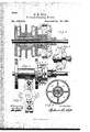
In the accompanying drawings, 'Figure l is Va longitudinal section of my invention, with 'shaft in el'evation.
Fig. 2 is a top view of my invention with the hub of the loose pulley, gear, clutch-couplin g, drinn, or wheel det-ached; Fig. 3 is a transverse section taken on the line u o, Fig. 1. Fig. 4 is an end vieW- of the sliding clutch-collar and stationaryl hub with spring mechanism detached. Fig. 5 is a side view of a modiiicationot' my invention.
Similar letters and igures refer to similar parts throughout the several views.
Drepresents a shaft, to which the ianged collar Bis iirmly securedby feather and spline, or in other suitable manner.
Arepresents the hub of a loose pulley, clutchcoupling, gear, drum', or wheel, journaled upon the collar B. The inside face of flange on collar is one of the friction-surfaces of this mechanism. C represents a sliding iianged collar, the face of flange' forming the other frictionsurface of this mechanism. The said sliding iianged collar ,Op is provided with ordinary clutch-coupling"projections, which intercept corresponding projections of the hub E, said hub being securely fastened to the collar B.
Upon the periphery of the hub E are two or more lugs or projections, B, having apertures e. Between the sides o1" said apertures are fittedthellevers H, pivoted'upon the bolts or pins 3. The outer ends of levers H are pivoted upon the `bolts ,or pins 7, between the ears of the link-levers S. 'The other ends of said ,linlrllevers S are pivoted on the bolts orpins 4.0, betweenlears 011 the periphery of the sliding collar K, fitted to slide upon the feather U. The said sliding collar K is provided with a groove, r, into which is fitted the end ofa `*shifting lever to move said collar K along upon pressure is adjustable for the different `speeds vby the screws n.
The inner en ds of levers H are so constructed as to engage" the ends' of screws a, or equivalent adjustable mechanism, fitted to the iiange of the sliding fiianged collar C. The said screws?aareprov'ided with check-nuts 6, to securely'hold screws a in place when once adjusted. The inner ends of levers H are of such shape that when the outer ends thereof are thrown outward the inner ends act as cams against the head of screws a and force the sliding flanged collar C along the ian ged collar B. The inner ends of levers H are also provided with'projections t, which limit the movement of the sliding ring K by coming in contact with the lugs R.
The hub E is provided with lugs 4., having cylindrical apertures, through which pass the rods or boltsh, which are fastened to the sliding ilanged collar G. The lugs 4 are countersunk for the reception of one end of a spiral spring, P, which is Wound around rods h. To the end of said rods h are fitted nuts F, by which the' pressure of springs P to move the flanged collar C in the direction of the hub E is regulated. The object of said springs is to more readily releasethe friction-surfaces when the pressure on the same is withdrawn. When the parts are in position shown in Fig. 1 the IOO friction-surfaces are in contact. When the friction-surfaces are not in contact the sliding clutch-collar K is at as great a distance iroin the end of hub E as the projections t on levers H, when in contact with lugs R, will admit, and the sliding tlanged collar C is at its greatest distance from the ilange on collar B.
The operation of my invention is thus: Move the sliding clutcli-collar K along the shaft until it comes in contact with linb E, which will cause the outer ends of levers II to move from and inner ends to move toward the shaft I). The inner ends of said levers 1I, which are in contact with the head ot' screws A, act upon the saine as cams, imparting to the sliding anged collar() a movement along the Collar B, thereby binding the hubot the loose pulley, gear. clutch-coupling, druni,or wheel A between the frietion-surfaces of the taiiged collar B and sliding tianged collar C. It' the shaft is revolving, the motion will thereby be communicated to the loose pulley, gear, clutchcoupling, drinn, or wheel.
Under high rates ot' speed and heavy pressure on friction-surfaces there are other slibstances tliat are preferable to cast-iroii on castiron. To provideI for this the huh of loose pulley, gear, cliitcli-coiipliiig, drinn, or wheel is provided with cavities, into which can be properly fastened blocks rl, ot' wood, compressed paper, leather, or other suitable substance.
To properly liibricate the joui nal ot' the loose pulley, gear, clutch-coupling, drum, or wheel the collar B is provided with one or more chambers, 1U, which are lled with lubricant through channels 9. Said channels 9 are closed by plugs or screws 5. The lubricant is delivered on the journal throngli holes connectingchanibers 10 with the periphery ofjonrnal.
The means for operating the pivoted levers H shown in Fig. 5 consists ot' a sliding conical clutch-collar, K2, which, when moved along the shaft in the direction of hub E, acts as a. wedge upon the outer ends of levers H2 and forces them from the shaft. When the conical clutch-collar is drawn back the springs m2, actingl upon thc levers H2, force them toward the shaft 1).
The number of levers S and II, screws a, springs m, and lugs R vary with diiiereuesized friction devices,the number being proportioned to the load the friction device has to carry.
.From the foregoing it is evident that many slight changesin the construction and arrangement of parts and materials employed maybe resorted to without departing from the spirit of niy invention, and hence I would have it understood that I do not limit myself to the exact construction shown and described.
IIaving thus described my invention, I claim as new and desire to secure by Letters Patclit- '1. In a friction-coupling device, the combination, with a shaft and a sliding collar mounted thereon, and provided with rods having spiral springs and adjusting-nuts, oi' a hub secured to said shaft, and having projections provided with apertures, through which said rods may pass, whereby said sliding collar is drawn toward said hub when relieved from pressure, substantially as described.
L. In a friction-coupling device, the combination, with the shaft D, ofthe fast collar B, loose pulley or wheel A, sliding collar U, having screws a, tixed hub E, having lugs or arms 1t, cani-levers II, pvoted to said arms, springs m, screws n, links S, and sliding clutch-collar Ix', the said hub l) being adapted to engage and rotate the said collar C, all substantially as set foi-th.
RICHARD Il. HILL.
'itnesses:
Gmo. 15. WALToN, ALBERT M. HILL.
Publications (1)
| Publication Number | Publication Date |
|---|---|
| US236814A true US236814A (en) | 1881-01-18 |
Family
ID=2306173
Family Applications (1)
| Application Number | Title | Priority Date | Filing Date |
|---|---|---|---|
| US236814D Expired - Lifetime US236814A (en) | Friction-coupling device |
Country Status (1)
| Country | Link |
|---|---|
| US (1) | US236814A (en) |
Cited By (1)
| Publication number | Priority date | Publication date | Assignee | Title |
|---|---|---|---|---|
| US3407446A (en) * | 1967-05-15 | 1968-10-29 | Ideal Ind | Stop control for textile sliver coiler head |
-
0
- US US236814D patent/US236814A/en not_active Expired - Lifetime
Cited By (1)
| Publication number | Priority date | Publication date | Assignee | Title |
|---|---|---|---|---|
| US3407446A (en) * | 1967-05-15 | 1968-10-29 | Ideal Ind | Stop control for textile sliver coiler head |
Similar Documents
| Publication | Publication Date | Title |
|---|---|---|
| US236814A (en) | Friction-coupling device | |
| US306267A (en) | Power-transmitting pulley | |
| US802175A (en) | Clutch and changeable-speed and reversing-gear mechanism. | |
| US1017893A (en) | Change-speed gearing. | |
| US1147104A (en) | Friction-clutch. | |
| US661909A (en) | Friction-gearing. | |
| US1279243A (en) | Clutch. | |
| US737477A (en) | Fly-wheel. | |
| US345670A (en) | campbell | |
| US940889A (en) | Reversing-gearing. | |
| US500289A (en) | Clutch-pulley | |
| US929049A (en) | Variable-speed pulley-drive. | |
| US915900A (en) | Clutch-gearing. | |
| US887779A (en) | Clutch or brake. | |
| US483892A (en) | Friction device | |
| US757014A (en) | Friction-gearing. | |
| US202400A (en) | Improvement in friction-clutches | |
| US625349A (en) | Mechanical motor | |
| US386719A (en) | Friction-pulley | |
| US705273A (en) | Clutch. | |
| US811041A (en) | Clutch. | |
| US456571A (en) | Friction-clutch | |
| US464798A (en) | Expansion-pulley | |
| US491444A (en) | Charles k | |
| US722245A (en) | Variable-speed-transmission mechanism. |