US236262A - richardson - Google Patents
richardson Download PDFInfo
- Publication number
- US236262A US236262A US236262DA US236262A US 236262 A US236262 A US 236262A US 236262D A US236262D A US 236262DA US 236262 A US236262 A US 236262A
- Authority
- US
- United States
- Prior art keywords
- cord
- tag
- fingers
- carriage
- horn
- Prior art date
- Legal status (The legal status is an assumption and is not a legal conclusion. Google has not performed a legal analysis and makes no representation as to the accuracy of the status listed.)
- Expired - Lifetime
Links
- 230000033001 locomotion Effects 0.000 description 14
- 238000010276 construction Methods 0.000 description 2
- 238000004080 punching Methods 0.000 description 2
- 230000015572 biosynthetic process Effects 0.000 description 1
- 238000003780 insertion Methods 0.000 description 1
- 230000037431 insertion Effects 0.000 description 1
- 238000000034 method Methods 0.000 description 1
- 239000011435 rock Substances 0.000 description 1
Images


Classifications
-
- B—PERFORMING OPERATIONS; TRANSPORTING
- B31—MAKING ARTICLES OF PAPER, CARDBOARD OR MATERIAL WORKED IN A MANNER ANALOGOUS TO PAPER; WORKING PAPER, CARDBOARD OR MATERIAL WORKED IN A MANNER ANALOGOUS TO PAPER
- B31D—MAKING ARTICLES OF PAPER, CARDBOARD OR MATERIAL WORKED IN A MANNER ANALOGOUS TO PAPER, NOT PROVIDED FOR IN SUBCLASSES B31B OR B31C
- B31D1/00—Multiple-step processes for making flat articles ; Making flat articles
- B31D1/02—Multiple-step processes for making flat articles ; Making flat articles the articles being labels or tags
- B31D1/023—Attaching wires or threads
-
- Y—GENERAL TAGGING OF NEW TECHNOLOGICAL DEVELOPMENTS; GENERAL TAGGING OF CROSS-SECTIONAL TECHNOLOGIES SPANNING OVER SEVERAL SECTIONS OF THE IPC; TECHNICAL SUBJECTS COVERED BY FORMER USPC CROSS-REFERENCE ART COLLECTIONS [XRACs] AND DIGESTS
- Y10—TECHNICAL SUBJECTS COVERED BY FORMER USPC
- Y10S—TECHNICAL SUBJECTS COVERED BY FORMER USPC CROSS-REFERENCE ART COLLECTIONS [XRACs] AND DIGESTS
- Y10S493/00—Manufacturing container or tube from paper; or other manufacturing from a sheet or web
- Y10S493/961—Tag, marker, or label
Definitions
- This invention relates to the construction of a machine for making that class of paper tags which are provided with a loop of cord intro,
- A is the bed-plate, upon which the operative mechanism of the machine is arranged.
- B B are two uprights supporting the driv- 2 5 ing-shaft B in suitable bearings 13 power being applied to the shaft through a pulley, B or otherwise.
- the cross-head B carries at its lower end a die or cutter, C, of the shape corresponding to the shape of the tag to be produced.
- a die or cutter, C of the shape corresponding to the shape of the tag to be produced.
- a corresponding die, C which, together with the cutter 0, serves to cut the tag in similar manner to punching or cutting presses.
- the upper or movable die is provided with a punch, C and the lower die with a corresponding perforation. (see Fig. 3,) which,
- the strip of paper from which the tags are to be cut is supplied from a roll, D, at the rear, and passes in between a pair of feed-rolls, D, (see Fig. 3,) to which the requisite intermittent moveinent is impartedto deliver to the die the requisite length of paper to form the (Model) tag.
- Any feeding device which will thus doliver the paper will answer the same purpose.
- Through the upper die there is a vertical spindle, E, rigidly attached to a stationary bar, E, there being an opening, E in the cross-head, through which this permanent connection is made.
- This spindle extends downward near to the lower die, its lower end fitted with a foot, E which rests upon the up-.
- the cord-introducing device is shown in enlarged view, Fig. 3.
- This consists of a bent tube, a, arranged upon a carriage, a, to which a reciprocating movementis imparted by means of a grooved cam, a on a counter-shaft, 003, to which revolution is given from the drivingshaft bymeans of bevel-gears, as seen in Figs.
- the connection from the cam a to the carriage a being made by the lever a, and so that the movement of the carriage is toward 8 and from the die in the same line of movement as that given to the paper.
- the cord drawn from a spool, a extends through the tube a a short distance, and so that as the carriage a is moved forward the tube a will present the protruding end of the cord directly over the hole in the tag held between the foot E and head F then a slight feed or forward movement is given to the cord, as hereinafter described, to pass its end through the said hole 5 :and' there be taken by a pair of fingers, b, which are also attached to and moved with the carriage.
- Thefingers b are opened, as seen in Fig.
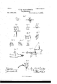
- the knot-tying device consists of a vertical spindle, e, terminating in a horn-shaped point, e, as seen in Fig. 7.
- This spindle is provided with a toothed pinion, c engaging with a stationary rack, 0 (seen enlarged in Fig. 8,) and so that as the carriage d, earryin g the spindle 0, moves to the right and left the rack and pinion cause a revolution of the said spindle 0.
- the horn is composed of two parts, divided horizontally at the point, the lower part, 0, arranged for vertical movement, as seen in Fig. 7, the two parts forming a pair ot'jaws, the lower or movable one held up in contact with the other or stationary jaw by a spring, 0 and operated as hereinafter described.
- a cutteinf (see Fi 9,) on the outside of the jaw f, severs the cord near the end of the tube a; also, at the same time apair of fingers, h h, grasp the tag at the right-hand side.
- These fingers h h are, in connection with a carriage, 7L2, moved by a cam, W, in a line parallel and simultaneous with the carriage d, and so that the tag, with the cord in the grasp of the jawsff, will be moved to the right, and in this movementthe end of the horn 0 passes over the double cord, as seen in Fig. 10, side view, and Fig. 11, top view.
- the tag is brought forward to give sufiicient slack to the cord to form the loop.
- the fingers 71 h are arranged upon a slide, 71.4, (see Fig. 17,) at right angles to the carriage W, and so as to move with the said carriage h the slide h is moved by a cam, lr", through a bell-crank lever, h, (see Fig. 1,) and as soon as the knot is tied, as before described, the cam 705 moves the fingers backward, drawing the ends of the tied cord or loop from the grasp ofthe born.
- the fingers h It are then opened, and the tag, with its loop complete, is dropped onto a carrier or endless band, L, which carries it from the machine, or it may be otherwise delivered.
- the fingers h It stand open by the force ofa spring, (not shown,) but as they advance to take the tag a ca1n,h", hinged in the tail of the upper finger, comes in contact with a stationary stud, It, which causes the cam k to press upon the tail of the finger h, and so as to close the fingers upon the tag; then on their return, and in the final movement, the cam h is tripped by coming in contact with a stationary shoulder, 7L9, as seen in Fig. 18. 4
- Fig. 19 The feed of the cord before mentioned, and which causes its end to pass through the hole in the tag, is shown in Fig. 19.
- This consists of a slide, a serrated or roughened upon its under side so as to extend into the tube and bear upon the cord.
- On the carriage a is a rock-shaft, ad, with an arm, a extending downward, (see Fig. 19,) and which, at the extreme rear movement of the carriage a, strikes a stud, a, turning the shaft outward.
- An arm, a extends upward and strikes a stud, a, on the slide a, throwing it back to its extreme point. Then, when the pass the end through the hole in the tag, as.
- the fingers b are opened andclosed by means of the said rock -shaft M, as seen in Fig. 4.
- the fingers are attached, respectively, to a slide, b one above the other. From the slide 1) a stud, b extends upward, and from the other slide, W, a
- the lifter l is raised, as before described, by
- a bell-crank lever, I hung upon the carriage 61, one arm of which operates against a stud, l, on the lifter, and the other arm strikes a stationary lug, L as seen in Fig 8 and rides on the lug during the time the lifter is raised, then passes ofi" from the lug, .permitting the lifter to drop, and as the carriage returns the bell-crank lever Z passes over the lug 1 withoutett'ect upon the lifter.
- a spring, 1, acts upon the bell-crank lever L, tending to hold it in its normal condition, yield to its movement in either direction because of its contact with the lug l and return it to its normal condition when it escapes from the said lug.
- the tags may be cut in another machine and successively presented to the holding device by hand or otherwise. In that case the cuttin g-dies and feed would be dispensed with.
- I claim- 1 The combination of a feeding device to deliver the paper, dies to cut and punch the tags, with the foot E and head F, to hold the tag after the dies have separated, and the fingers h h, to take the tag from between the head and foot, substantially as described.
Landscapes
- Labeling Devices (AREA)
Description
0. M. rucmmasolv.
Tag Machine.
"No- 6262. Patented Jan. 4,1881.
1'07: a l-also 72,
N- FET E113. FHOTO-UTHOGRAFHER, VIASHRIGYON. D. C,
(Model) 3 Sheets-Sheet 3.
(1 RICHARDSON; TagMa'chine. Y No. 236,262. Patented Jain. 4,1881.
a 5%,; Fla 2am I :77: 7/673 5 UNITED STATES PATENT OFFICE.
CHARLES M. RICHARDSON, OF BRIDGEPORT, CONNECTICUT, ASSIGNOR TO WILLIAM C. WILDMAN, OF SAME PLACE.
TAG-MACHINE.
SPECIFICATION forming part of Letters Patent No. 236,262, dated. January 4:, 1881.
Application filed April 16, 1880.
To all whom it may concern:
Be it known that I, CHARLES M. RICHARD- SON, of Bridgeport, in the county of Fairfield and State of Connecticut, have invented a new Improvement in Machines for Making Tags; and I do hereby declare the following, when taken in connection with the accompanying drawings and the letters of reference marked thereon, to be a full, clear, and exact description' of the same, and which said drawings constitute part of this specification.
This invention relates to the construction of a machine for making that class of paper tags which are provided with a loop of cord intro,
duced through a perforation in the tag, the
object being to cut and pierce the tag, introduce the cord, and tie the two ends of the cord together to complete the loop; and the invention consists in the construction as hereinafter described, and particularly recited in the claims.
A is the bed-plate, upon which the operative mechanism of the machine is arranged.
B B are two uprights supporting the driv- 2 5 ing-shaft B in suitable bearings 13 power being applied to the shaft through a pulley, B or otherwise. On the uprights B guides B are placed, between which the cross-head or gate B is arranged, and to which a verticalo reciprocating movement is imparted by acrank or eccentric, 13 ,011 thedriving-shaft B, through a pitman, B substantially as in common punching or power presses.
The cross-head B carries at its lower end a die or cutter, C, of the shape corresponding to the shape of the tag to be produced. Below the cutter C is a corresponding die, C, which, together with the cutter 0, serves to cut the tag in similar manner to punching or cutting presses. The upper or movable die is provided with a punch, C and the lower die with a corresponding perforation. (see Fig. 3,) which,
when the dies come together, punch the hole for the insertion of the cord.
The strip of paper from which the tags are to be cut is supplied from a roll, D, at the rear, and passes in between a pair of feed-rolls, D, (see Fig. 3,) to which the requisite intermittent moveinent is impartedto deliver to the die the requisite length of paper to form the (Model) tag. Any feeding device which will thus doliver the paper will answer the same purpose. Through the upper die there is a vertical spindle, E, rigidly attached to a stationary bar, E, there being an opening, E in the cross-head, through which this permanent connection is made. This spindle extends downward near to the lower die, its lower end fitted with a foot, E which rests upon the up-. per surface of the paper, but is smaller in ex- 6 tent than the tag, and remains stationary while the die C moves up and down. Through the lower die, C, is a similar spindle, F, fitted at its upper end with a head, F, corresponding to the foot E of the other spindle, (see Fig. 3,) and around the spindle is a spring, F the tendency of which is to force the head F upward, the head F standing beneath the paper, and sothat the head F and foot E form a pair of jaws to gripe the paper within the dies, and so as to hold the tag, after it shall have been cut and punched by the dies, until the gripe of the head F be released, which is done at the proper time, as hereinafter described.
The cord-introducing device is shown in enlarged view, Fig. 3. This consists of a bent tube, a, arranged upon a carriage, a, to which a reciprocating movementis imparted by means of a grooved cam, a on a counter-shaft, 003, to which revolution is given from the drivingshaft bymeans of bevel-gears, as seen in Figs.
1 and 2, the connection from the cam a to the carriage a being made by the lever a, and so that the movement of the carriage is toward 8 and from the die in the same line of movement as that given to the paper. The cord drawn from a spool, a extends through the tube a a short distance, and so that as the carriage a is moved forward the tube a will present the protruding end of the cord directly over the hole in the tag held between the foot E and head F then a slight feed or forward movement is given to the cord, as hereinafter described, to pass its end through the said hole 5 :and' there be taken by a pair of fingers, b, which are also attached to and moved with the carriage. Thefingers b are opened, as seen in Fig. 4, to receive theeud of the cord,and are after described, and so that as the carriage a is drawn back the fingers I) will draw the ends of the cord through the tube, and the hole in the tag, doubling the cord, as seen in Fig. 5, until the requisite length to form the loop has been drawn from the spool or supply. The carriage a then stands still, the fingers I) holding the end of the cord in close proximity to the end of the tube, so that the two strands lie close together, as seen in Fig. 5. During the introduction and drawing out of the cord, asjust described, a transverse carriage, d, arranged in suitable guides d. and carrying the knot-tyin g device, has been moved so as to carry the said device to the left of the cord, as
seen in Fig. 6, enlarged. The carriage is thus moved by means of a cam, (1 through a lever, (1.
The knot-tying device consists of a vertical spindle, e, terminating in a horn-shaped point, e, as seen in Fig. 7. This spindle is provided with a toothed pinion, c engaging with a stationary rack, 0 (seen enlarged in Fig. 8,) and so that as the carriage d, earryin g the spindle 0, moves to the right and left the rack and pinion cause a revolution of the said spindle 0. The horn is composed of two parts, divided horizontally at the point, the lower part, 0, arranged for vertical movement, as seen in Fig. 7, the two parts forming a pair ot'jaws, the lower or movable one held up in contact with the other or stationary jaw by a spring, 0 and operated as hereinafter described.
On the carriage d, and immediately in front of the tip of the horn, is a stationary ja\v,f, and corresponding movablejawf, the movable jaw held up against the stationary jaw f by the springf (see Figs. 8 and 9,) their normal condition being closed. As the carriage d commences its movement to the right a bellcrank lever, f hung upon the carriage, one arm of which is connected to the slide carrying the jawf, strikes a stationary stud,f causing the movable jaw f to be drawn down, opening the jaws, so that they pass onto the double cord nearthe fingers b. Theleverf then escaping from the stud f thejaw f flies upward and grasps the double cord. At the same time a cutteinf (see Fi 9,) on the outside of the jaw f, severs the cord near the end of the tube a; also, at the same time apair of fingers, h h, grasp the tag at the right-hand side. These fingers h h are, in connection with a carriage, 7L2, moved by a cam, W, in a line parallel and simultaneous with the carriage d, and so that the tag, with the cord in the grasp of the jawsff, will be moved to the right, and in this movementthe end of the horn 0 passes over the double cord, as seen in Fig. 10, side view, and Fig. 11, top view. At the same time the cord just in rear of the horn is raised by a lifter, l, as seen in Fig. 12, and so that the point of the horn passes beneath that part of the cord at the rear, the ends being still held by the jawsff, and so as to form a loop around the tip of the born,
as seen in Fig. 13, continuing its revolution ntil the point of the horn comes again in front of the jawsf. (See Fig. 14.) At this time one arm of a bell-crank lever, 0 strikes a stationary stud or shoulder, 0 causing the lever to turn and draw down the'lower part or jaw e of the horn. Then, as the revolution ofthe horn continues, the open end passes onto the cord at the jawsf, (see Fig. 15,) and the lever 0 escaping from the shoulder e", permits the born to close upon the cord near the ends with sufiicient force that by the continued revolution of the horn the ends of the cord will be drawn from the jaws f, and the loop which has been formed around the horn in its revolution will slip from its point onto the cord itself, as seen in Fig. 16, and complete the knot.
During the formation of the loop by the rotation of the horn the tag is brought forward to give sufiicient slack to the cord to form the loop. In order to give this forward movement, the fingers 71 h are arranged upon a slide, 71.4, (see Fig. 17,) at right angles to the carriage W, and so as to move with the said carriage h the slide h is moved by a cam, lr", through a bell-crank lever, h, (see Fig. 1,) and as soon as the knot is tied, as before described, the cam 705 moves the fingers backward, drawing the ends of the tied cord or loop from the grasp ofthe born. The fingers h It are then opened, and the tag, with its loop complete, is dropped onto a carrier or endless band, L, which carries it from the machine, or it may be otherwise delivered. The fingers h It stand open by the force ofa spring, (not shown,) but as they advance to take the tag a ca1n,h", hinged in the tail of the upper finger, comes in contact with a stationary stud, It, which causes the cam k to press upon the tail of the finger h, and so as to close the fingers upon the tag; then on their return, and in the final movement, the cam h is tripped by coming in contact with a stationary shoulder, 7L9, as seen in Fig. 18. 4
When the fingers take the tag, in order to release the grasp of the head F upon it, the spindle F is drawn down by means of the cam F striking an arm, F extending from the rock-shaft F and from which an arm, F extends inward into connection with the spindle F, so that the spindle F will be drawn down, as seenin broken lines, Fig. 3.
The feed of the cord before mentioned, and which causes its end to pass through the hole in the tag, is shown in Fig. 19. This consists of a slide, a serrated or roughened upon its under side so as to extend into the tube and bear upon the cord.
On the carriage a is a rock-shaft, ad, with an arm, a extending downward, (see Fig. 19,) and which, at the extreme rear movement of the carriage a, strikes a stud, a, turning the shaft outward. An arm, a extends upward and strikes a stud, a, on the slide a, throwing it back to its extreme point. Then, when the pass the end through the hole in the tag, as.
before mentioned. The fingers b are opened andclosed by means of the said rock -shaft M, as seen in Fig. 4. The fingers are attached, respectively, to a slide, b one above the other. From the slide 1) a stud, b extends upward, and from the other slide, W, a
like stud, 12 extends upward through a plate, b This plate I) has a reciprocating movement imparted to it by means of a cam, b on the rock-shaft a", and in the plate there are two converging slots, 1) and b through which the studs 1) and I) extend, and so that when the plate 11 is moved forward the said inclined slots force the fingers together to grasp the cord, and on the return of the carriage a the movement of the rock-shaft 0." draws the slideoutward and opens the fingers to release the end of the cord when it has been taken by the jaws ff. The devices for imparting the move ment to the parts may be changed, and other known mechanism for producing the same movement may be substituted.
The lifter l is raised, as before described, by
means of a bell-crank lever, I, hung upon the carriage 61, one arm of which operates against a stud, l, on the lifter, and the other arm strikes a stationary lug, L as seen in Fig 8 and rides on the lug during the time the lifter is raised, then passes ofi" from the lug, .permitting the lifter to drop, and as the carriage returns the bell-crank lever Z passes over the lug 1 withoutett'ect upon the lifter. A spring, 1, acts upon the bell-crank lever L, tending to hold it in its normal condition, yield to its movement in either direction because of its contact with the lug l and return it to its normal condition when it escapes from the said lug.
Itwill be understood that the usual methods of adjustment of parts in other machines are or may be employed in this machine to adapt it to various sizes and shapes of tags.
The tags may be cut in another machine and successively presented to the holding device by hand or otherwise. In that case the cuttin g-dies and feed would be dispensed with.
I claim- 1. The combination of a feeding device to deliver the paper, dies to cut and punch the tags, with the foot E and head F, to hold the tag after the dies have separated, and the fingers h h, to take the tag from between the head and foot, substantially as described.
2. The combination of dies to cut and punch the tags, fingers h h, to take the tag, with mechanism, substantially such as described, to present and introduce the cord through the hole in the tag, grasp the end of the cord and draw it through, and cutter and jawsf f, to
take the end of the cord, the said jaws f f and the fingers h h moving together away from the dies which cut the tag, substantially as described.
3. The combination of dies to cut and punch the tags, fingers h h, to take the tag, with mechanism, substantially such as described, to present and introduce the cord through the hole in the tag, grasp the end of the cord and draw it through, and cutter and jawsff, to take the end of the cord, and the revolving hdrn 6, moving with the said jaws ff, and the said fingers advanced to give snfficient slack for the horn to form the loop and knot, substantially as described.
4. The combination of dies for cuttingthe tag, mechanism, substantially such as described, to
*present and introduce the cord through the hole in the tag, and mechanism, substantially such as described, to take the two ends of the cord and form a knot, substantially in the manner specified.
5. The combination of mechanism, substantially such as described, for holding the tag, the reciprocating tube a, fingers b, cutter f divided revolving horn e, the two parts of the horn arranged to separate and close upon the ends of the cord after it has formed the loop for the knot, and the jaws f f substantially as described.
6. The combination of mechanism, substantially such as described, for holding the tag, with the reciprocating tube a and fingers b, jawsff, and cutter f substantially as described.
7. The combination of mechanism, substantially such-as described, for holding the tag, reciprocating tube a, and fingers b, with the feed a to advance the cord, substantially as described.
8. The combination of mechanism, substantially such as described, for holding the tag, reciprocating tube a, jaws ff, revolving born c, and litter l, substantially as described.
9. The combination of mechanism, substantially such as described, for holding the tag, reciprocating tube a, and fingers b, with the feed a to advance the cord, substantially as described. I
10. The combination of the feed-rolls, the punch and die, and the laterally-moving tagca-rrier, all substantially as described.
CHARLES M. RICHARDSON.
Witnesses:
FRANK B. TAYLOR, THOMAS 0. SMITH.
Publications (1)
| Publication Number | Publication Date |
|---|---|
| US236262A true US236262A (en) | 1881-01-04 |
Family
ID=2305624
Family Applications (1)
| Application Number | Title | Priority Date | Filing Date |
|---|---|---|---|
| US236262D Expired - Lifetime US236262A (en) | richardson |
Country Status (1)
| Country | Link |
|---|---|
| US (1) | US236262A (en) |
Cited By (1)
| Publication number | Priority date | Publication date | Assignee | Title |
|---|---|---|---|---|
| US2503902A (en) * | 1945-05-12 | 1950-04-11 | A Kimball Co | Method of attaching price tags |
-
0
- US US236262D patent/US236262A/en not_active Expired - Lifetime
Cited By (1)
| Publication number | Priority date | Publication date | Assignee | Title |
|---|---|---|---|---|
| US2503902A (en) * | 1945-05-12 | 1950-04-11 | A Kimball Co | Method of attaching price tags |
Similar Documents
| Publication | Publication Date | Title |
|---|---|---|
| US236262A (en) | richardson | |
| US557378A (en) | Bag-fastening machine | |
| US682228A (en) | Match-machine. | |
| US915862A (en) | Stapling mechanism. | |
| US1060168A (en) | Machine for making toggles. | |
| US241442A (en) | Wire-barbing machine | |
| US1031444A (en) | Baling-press. | |
| US743998A (en) | Knotting mechanism. | |
| US1140228A (en) | Mechanism for producing and applying wire lengths or other strips. | |
| US515143A (en) | Tying machine | |
| US801998A (en) | Box-making machine. | |
| US662662A (en) | Wire-fence machine. | |
| US457351A (en) | Kate t | |
| US249822A (en) | Needle blanks | |
| US1570198A (en) | Machine for making staples for mesh fabric | |
| US525351A (en) | Machine for making pin-tickets | |
| US1495040A (en) | Machine for making reenforced sanitary cups | |
| US1126202A (en) | Safety-pin machine. | |
| US314106A (en) | Machine for forming check-rower wire | |
| US379876A (en) | Machine for | |
| US1474874A (en) | Paper-baling machine | |
| US1046453A (en) | Bailing-machine. | |
| US238198A (en) | Administkatoe db | |
| US375149A (en) | Button-fastening machine | |
| US432123A (en) | duncan |