US2360988A - Undercarriage leg for aircraft - Google Patents
Undercarriage leg for aircraft Download PDFInfo
- Publication number
- US2360988A US2360988A US397485A US39748541A US2360988A US 2360988 A US2360988 A US 2360988A US 397485 A US397485 A US 397485A US 39748541 A US39748541 A US 39748541A US 2360988 A US2360988 A US 2360988A
- Authority
- US
- United States
- Prior art keywords
- cylinder
- leg
- valve
- piston
- accumulator
- Prior art date
- Legal status (The legal status is an assumption and is not a legal conclusion. Google has not performed a legal analysis and makes no representation as to the accuracy of the status listed.)
- Expired - Lifetime
Links
Images


Classifications
-
- B—PERFORMING OPERATIONS; TRANSPORTING
- B64—AIRCRAFT; AVIATION; COSMONAUTICS
- B64C—AEROPLANES; HELICOPTERS
- B64C25/00—Alighting gear
- B64C25/02—Undercarriages
- B64C25/08—Undercarriages non-fixed, e.g. jettisonable
- B64C25/10—Undercarriages non-fixed, e.g. jettisonable retractable, foldable, or the like
- B64C25/18—Operating mechanisms
- B64C25/22—Operating mechanisms fluid
Definitions
- This invention relates to -undercarriages vfor .aircraft (including ⁇ seaplanes) and in particular to Wheel (and/or float) .supporting legs therefor.
- the invention hasl foran object to provide improved retractable undercarriage legs in which hydraulic means may serve to eiectretraction and extension and also to damp Wheel or float movements when 'landing or taxiing.
- Anv undercarriage leg according tothe inven- -tion comprises the combination of la telescopic member and ⁇ a, radius member ⁇ pivoted about spaced parallel axes tothe airframe with means Vfor connecting the outer endfof. the radius memlber alternatively to theanchored and tothe movable lparts respectivelyof the telescopic member.
- van undercarriage vleg mounted for pivotal retracting and lowering movementand comprising a telescopic member, one part of which is pivotedand the other part of which is movable longitudinally relatively to the first when in the lowered position, has means for positively Aeffecting such relascopic memben'meansmay be provided for applying ⁇ boost pressure from an external source to a piston carried by the movable part of the telescopic member and sliding within the anchored part vtl'1ereoi,either a-closed, or an open, circuit liquid pressure system being employed.
- the telescopic member will as a .Whole constitute'the leg proper, and the'anchored orcylinder part thereof Imay bein communication with a reservoir :or air accumulator for pressure :liquidso that-liquid displacedupon shortening of theitelescopic leg due to consequent reduction of liquid space within the cylinder Will pass to .this-accumulator and so build-up pressure therein,
- a passage to the accumulator from the cylinder may have a restriction, there being little or no resistance to the ilovv of liquid from one side of the piston to the other.
- This restriction may be adjustable automatically upon' change in length of the telescopic member so that the more the latter is shortened the greateres the resistance to flow of liquid therethrough tothe accumulator,
- such restricted passage may be bypassed by 'an outlet vcontrolled by a non-return valve so that there will be li-ttle'or no resistance to iioW of liquid from the accumulator and so to the lengthening of the telescopic member.
- the yair accumulatorf may have three connections with the control valvez'one a "direct connection closed yor opened by said Valve, the second an outlet controlled lby -a non-return 4valve and the third by Way of an adjustable restriction valve; the control valve setting for lengthening, or tending to lengthen, the telescopic member beingsuch as to close the direct connection and rleave the restriction valve connection open so that shortening movement of the telescopic .member underwload will be resisted by the restriction .of liquid dow thereto via4 the restriction valve, as well as -by consequent increase of pressure in the air accumulator, YWhereasv :lengthening movement of the vtelescopic member k will not be so hindered owing Ato the comparative ⁇ ease with which liquid may leave the accumulator under the pressure therein via the .non-return valve outlet.
- Such provision will tend effectively tomaintain contact of al-landing Wheel with the ground should Athe
- the ypump delivery is connected to the cylinderabovethe piston and the pump return is connected not only rt0 the cylinder below the piston but also to the accumulator so .
- the telescopic member for connecting the outer end of theradius vmember alternatively with the. anchoredand
- the movable parts respectively of ⁇ the telescopic member comprises a lug on the radius member having oppositely directed notches for engage- ,ment with transverse engagement projections or the like on said parts, respectively, of the telescopic member, a ⁇ substantially E-shaped latch member pivoted about the end of this centre limb on the lug at a point between said notches forA angular movement in the one direction to a position in which one outer limb thereof extends across one notch to retain the corresponding engagement projection therein andthe other limb is withdrawn clear of the other notch, and for.'y
- the latch member is preferably spring-iniiuenced to tend always to assume a position in which it closes pressure liquid at the top thereof at 32, and an hydraulic cylinder therein at 33, see Figs. 10 and 15.
- of the leg is formed with passages to be described below for pressure iiuid which are controlled by a rotary control valve 34 and an .automatically adjusted rotary restriction valve 35.
- is intended to be pivoted about an axis indicated at A-A to an airframe (not shown) for which purpose it is provided with trunnions 36.
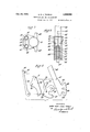
- the movi able part of the telescopic member is in the form larger scale illustrating a catch device whereby the radius member is connected for landing with the anchored part and for ⁇ retraction with the moving part of the telescopic member, Fig. 3 -being a part sectional elevation of this catch fully engaged with the 4anchored part, Figs. 4 and 5 showing the catch at early stages in the retracting, or'late stages in the lowering, movement of the leg, Fig. 6 showing the catchiully engaged with the moving part of the telescopic member, Fig. I being a section on the line T-'l of Fig. 3, the catch device being omitted, and Fig. 8 avlew of the catch as seen from the left hand side of Fig. 3, whilst Fig. 9 shows the several parts [of the catch separated from one another. f
- Fig. A1() shows inv sectional elevation, also to larger scale, the essential features of a telescopic member andthe means for connecting it for lengthening Vand shortening movement with.
- a closed circuit 'liquid pressureV system Figs. 11, 12, 13 and 14 being developments of the obturating surface of a control valve indicating the modications to connections for pressure liquid effected thereof at four diierent settings.
- Fig. 15 is a view similar to Fig. 10 of a telescopic member for operation from an open liquid pressure system, Figs. 16, ⁇ 17, 18 and 19 being views similar to Figs. 11, 12, 13 and 14 of the obturating surface of the control valve thereof.
- Fig. 20 is an enlarged sectional view of a detail of Figs. 10 and 15. n
- Fig. 21 is a cross-section on the line 2
- Fig. 22 is a diagram drawn t-o thel smaller scale showing in elevation a pilots control lever and the connections thereof with the control valve and the radius member catch rand the holdingy catch, Fig. 23 showing the control lever in' plan and Fig. 2.4 being a face view of a gate associated with the control lever.
- the anchored cylinder part of the telescopic member, or leg proper is indicated generally at 3
- the ram 3l is attached rigidly to a mounting 39 for a wheel 40 from which there extend upwardly alongside the ram 3l and cylinder part 3
- are gaped (see Fig. 2) to give passage to the pin 50 as itl moves between the full line and broken line positions of Fig. l.
- these slide rods 4I serve to prevent twisting of the wheel or at least of the wheel 39 mounting about the axis of the ram 31 and cylinder part 3
- pivots For supporting the leg against any tendency to movement in a plane containing its pivotal axis A--A there extend from pivots, one of which is indicated at 43 Fig. 2, coaxial with the main leg pivot and spaced at opposite sides of the leg respectively, two rigid struts 44 (Fig. 2) which are attached to lugs 45 formed on the cylinder part 3
- a rigid radius member 46 (Fig. l) is pivotally attached at its upper end to the airframe (not shown) at a point 41 slightly below the level of the axis A-A of the main leg pivot and to one side thereof.
- a catch device is provided whereby the lowerl end of this radius member 46 is attached to the "lower end of the cylinder part 3
- a lug 48 on the lower end of the radius rod 46 projects laterally therefrom towards the leg, above a substantially rectangular section bridge piece 49 linking the slide rod guides 42 at the lower end of the cylinder part 3
- the lug 48 is formed at its underside with a deep square notch 52 to lit closely over, or to receive, the bridge piece 49 and at its upper side with a rounded V-shaped notch 53 to cooperate with the bridge pin 5i).
- theilug '48 is'bifurcated (seeFigJS) ⁇ and there is mounted thereon between theibifurcations thereofifor movement fabout a -pivot55 ya substantially E-shaped latch 'member '54.
- this ladditional rocking of the latch member 54 is to initiate an operation Iwherebysaid member 54 is locked or held ⁇ in position during retraction until the leg is again 'lowered for use.
- This double rocker 54 co- -operates through the medium of'thefcross bar -51 -tached .at points fil-l fto :theftwo parts x ⁇ 64, ⁇ respecitively, of the :double concept
- Controlmeans fully described' below and ⁇ indicated generally at 3
- the restriction valve is connected for rotation with shortening or lengthening of the leg (see Fig. l) with the slide rods 4
- the valve 35 is completely closed when the ar
- the restriction valve 35 is of simple type, the
- 22 disposed coaxially within the cylinder 33 and which is secured at its closed upper end to the upper end of said cylinder 33.
- 22 extends downwardly into a coaxial bore
- 22 seals off high pressure .compressed air contained in said cylinder
- 22 is closed by a screw plug
- 21 acts by bearing at one end on the outer face of the plug
- The. shortening movement of the leg is effected by setting the control'valve 34'to the position shown in Eig. 12 whereby the pump delivery passage
- 06 is closed.
- the'control valve 34 For normal lowering ⁇ the'control valve 34 is set to the position of Fig; 11, discussed above, as for landing and taxiing when, the holding catch ⁇ 330 being released, the pressurein the accumulator 32 causes the return of liquid therefromto the cylinder 33 as'a whole, and', astheiarea ofthe pistonV 38 at which the pressure' ⁇ fluid can act at the upper sidethereof isrgreater ⁇ than the area at :the Aunderside of.A the piston v3
- the valve'leg arrives the" fully. loweredU position the lower end" of tney radius*y member 46' is' once again atL tach'ed t'o thev lower end ofi the cylinder" partv 3 in tl'emanner describedabove.
- the -arrangementiillustrated in-iFigsr.j ⁇ 15tof 19 is essentiallythe same' asg'tha-t offFigs. 10? to 14 but has provision for operation from f' an open' circuit liquidlpressure system, e; g., the'existing liquid pressure system of an aircraft.
- valve 34 differs somewhat from that of Fig. 10,'v liquid connections 202 and ⁇ 203 coaxial with the pivot of the cylinder part ⁇ 31 connecting, respectively, with the pressure and exhaust sides of the open circuit liquid pressure system. From these connections 202 and 203 liquid passages extend to the chamber of the valve 34 and are indicated at 204 and 205 respectively, a direct passage 206 from the accumulator 32 connecting with the valve chamber v ia the ⁇ end portion of the passage 205.
- This direct passage as well as a connection 201 for introducing air under pressure into the accumulator 32 are controlled by non-return valves 208 and '209 respectively, influenced by a common coil compression spring 210 interposedbetween them.
- a further passage 21 I from the Yvalve chamber leads to a nonreturn valve 212 equivalent to the non-return valve 106 of Fig'. 10 and lto the restriction valve 35 placing the valve chamber in connectionv with the accumulator 32 via said restriction valve 35 and a further passage 213.
- Further passages 214 and 215 respectively extend between the valve chamber and the cylinder. 33 above the piston 38 and the cylinder 33.below'.the piston 38 respectively.
- the passage 205 communicates with the exhaust connection 203 by way of a piston valve 216 influenced by a compression spring 211 to 'bear on a seating 218 ofconsiderably smaller diameter than the valve 216 the arrangement being such thatthe liquid pressure acting on the valve within the seating 218 to open it against
- the settings of the valve 34 of Fig. 15 illus- A trated inFigs. 16 to 19 have 4the same effect upon the operation of the legas thesettings ofthe valve 34 of Fig. 10 illustratedinFigs. 11 to 14 of the drawings.
- valve In order that pressure in the accumulator 32 may tend to lengthen the leg the: valveis set to the position of Fig. 16.in which the passages 214 and 215 fromv the cylinder 33 above and below the piston 38, respectively, are connected via the groove220 with the passage 211 leading to the non-return valve 212 and restriction valve 35, the connection 205 leading to the accumulator-32 and to the valve 216 is closed, and the connection 204 from the pressure side ⁇ of the liquid pressure system, although open to interconnecting passages 221 within the valve body, is in eiect closed.
- the valve 34 is set to the position ci Figgl'i so that the pump delivery passage 204 is connected via the groove 222 in the valve surface with thepassvage 215 leading to below the piston 38, the passage 214 from the cylinder 33 abovethe piston 38 is connected via the passage 2211 with the passage 205 leading to lthe ⁇ accumulator 32 and to the valve 216, whilst the passage 211 leading to the non-return valve 212 and restriction va1ve35 Liquid pressure then *raises the d e liquid from the upper side of the latter passes gaat@ by way or the valve 34, passages 205 and 206 and non-return valve 208 into the accumulator 32, this valve 200 andthe valve 216 being such that the valve 216 willremain closed until the pressure which is built up in the accumulator 32 is suflicient for the purpose of subsequently lengthening the leg lfor lowering.
- valve When desired, for example when the leg is in the retracted position, the valve may be set to the position of Fig. 18 in which all the passages are closed.
- valve 34 For lengthening the leg by pressure from the hydraulic system, the valve 34 is set to the position of Fig. 19 thus connecting the passage 204 via the valve groove 222 with the passage 214 leadingto the upper side of the piston 38 and connecting also via the valve passages221 the passage 215 from the lower side of the piston 38 with the passage 205 leading to the accumulator 32 andto the exhaust, and incidentally with the passage 211 leading to the non-return valve 212 and restriction valve 35.
- a main control lever 3011 is mounted forangular movement about a spindle 302 within a gate 303 (Fig. 23).
- This gate having side notches 304, 305, 306 and 30'1 which in practice might be marked, respectively,
- sprocket 310' is a double one and has extending therearound two lengths of sprocket chain 312 Fig. 22 the ends of which are secured to Bowden wires313xof which thosev of one chain 312 lead to one telescopic leg and those of the other chain 3
- 3 is connected with the ends of a second length of chain 3
- the valve 34 projects into the interiorl of this box 3
- 4 is formed with arnotch 322 intowhich projects a pin 323 extending rigidly from the near end ofthe stem 3
- Thisindependent shifting of the control valve 34' will be of service in cases where it is desired to raise or lower the airframe in relation to the wheels or floats which will be useful forpurposes of storage where head room is limited asin-the case of ⁇ an aircraft carrier.
- the holding catch comprises simply a catchmember 330 fulcrumed at,y
- valve 34 When the leg is in the lowered position4 the valve 34 will occupy the position of Fig. 11, or 16, and the cam 325, and therefore the rocker 326, will occupy the positions'shown iny full lines in Fig. 21 that is pulling the Bowden wire 328 andslackening the Bowden wire 323 and so maintaining the holding catch 330in the released position and allowing the springs of the v radius member catch device to hold thelatter connected to the cylinder part 3
- simple- 1 pull wires may be provided whereby the holding catches 330 Vmay be released at will, when, the valve 34fhaving been left in the normal' lower position, the legs willl automatically per; form the lowering operation under the iniiuence of pressure stored in the accumulators, so long as these latter are not damaged.
- the cam 325i androcker 326 areso shaped that the additional movementl imparted to the formery by further rotation of the valve 34y consequent upon movement of the lever 30
- a pin 333 is normallyy secured in position across the gate '303 between the flower and emergency lower notches 306 and 301 by such means as a lead seal which must ⁇ be broken by the removal ofthe pin 333 to enable the lever 30
- the wheel movements will vfirst be controlled bythe restriction valve and by the lower pressure air in the accumulator, and subsequently, as more' of the weight of the aircraft is transferred to the wheels, by the high pressure air in the high pressure air cylinder as well.
- the control of the wheel movements may be regarded as having two phases which so to speak merge into one anotheraccording to the wheel loading or the shock forces acting thereon at any part of the inward stroke of the ram.
- the axes o f the leg pivots may be disposed longitudinally or transversely of an aircraft, or in some intermediate position.
- Undercarriage legs according to the invention may be of service for raising and lowering an airframe in relation to landing wheels or oats ⁇ which may be of great importance for storage where head room is limited.
- undercarriage legs in accordance withthe invention in no way precludes or interferes with the provision of means already known in undercarriages such forl example as wheel brakingsystems lfor steering when taxiing, ,or castoring wheels enabling an aircraft t be landed across wind with the wheels in the direction of night, or landing and the head of the craft into the wind.
- wheel brakingsystems lfor steering when taxiing, ,or castoring wheels enabling an aircraft t be landed across wind with the wheels in the direction of night, or landing and the head of the craft into the wind.
- a What I claim is: Y.
- an undercarriage Aleg comprising rin combination a telescopic member pivotally anchored at one of its two relatively slidable parts to the airframe, a radius member pivotally attached at one end to said airframe about an axis ⁇ spaced from and parallel with that of the pivotal anchorage of the telescopic member to.
- said airframe and catch means whereby the other end of theradius ⁇ member is connected with the pivotally anchored part of the telescopic .member when the leg is in the lowered position and at other times ⁇ with the other relatively slidable part of the telescopic member, said catch meansy comprising a lug on said other end of ,the radius member having oppositely directed notches, adapted to receive transverse projections carried bythe pivotally anchored part of the telescopic member and by the moving part of the telescopicmember, respectively, hydraulic means being provided for moving the movable part of the telescopic member. relatively to the pivoted part.
- an undercarriage leg comprising in combination a telescopic member composed of two relatively slidable parts one ofgwh'ich is anchored at one end to the airframe, a radius member pivotally attached at one end 4to said airframe about an axis spaced from and parallel with that of the pivotal anchorageof the telescopic member to said airframe, and a catch mounted on the other end of said radius member adapted to engage selectively projections carried respectively by the pivotally anchored part of the telescopic member and by the other relatively slidable part of said telescopic member whereby said radius member is connected with the pivotaly anchored part of the telescopic member when the ,leg is in the lowered position and at other times with the other relatively slidable part of said telescopic member.
- the said telescopic member having oleo-pneumatic means for damping motion of the said slidable member relative to said pivotally anchored part, comprising a piston carried by the vrelatively slidable part movable within a cylinderk located within the pivotally anchored part against a body of air pressed liquid, a supplemental cylinder located within said relatively slidable part of said telescopic member, a piston located therein, a volumen-f compressed air of higherv pressure than that insaid first mentioned cylinder on one side of said piston and a restricted communication from said first mentioned cylinder to the cylinder located within said slidable member on the oppoiste side of said last-mentioned piston.
- an undercarriage leg comprising .in combination a telescopic member pivotally anchored at one of its two relatively-slidable parts tothe airframe, a radius member pivotally attached at one of its ends to said airframeabout an axis spaced from and parallel with that of the pivotal anchorage of the telescopic member to said airframe, and catch means mounted on the other end of said radius member adapted to connect said radius member with the pivotally anchored part of the telescopic member when saidtelescopic member is extended and at other times with the other relatively slidable part of said telescopic member, saidA catch means comprising a lug on saidother end 'of the radiusmember having oppositely directed notches adapted to receive transverse projections carried by the pivotally anchored part of the telescopic member and by the other relatively slidable part thereof, respectively, a substantially E-shaped latch member pivoted about the end of its center limb on the lug at a point between said notches for ang
- An undercarriage leg as claimed in claim 4 having a detent pivotally mounted on the latch member and a rocker pivotally mounted on saidradius member and connected by a spring to said detent to hold said detent in engagementwith said rocker, cam means carried by the pivotally anchored part of the telescopic member cooperating with saidrocker and one of said outer limbs of said latch member to shift the detent between positions where said detent is operative and inoperative respectively.
- said latch member having a spring connecting it to a detent pivotally mounted at one end on said latch member, extending longitudinally of the radius member and provided with an undercut nib at its other end adapted to engage an undercut lip on said radius member, a rocker pivotally mounted at one end on said lug and bearing against said detent, a cam comprising said transverse projection carried by the pivotally anchored part of the telescopic member cooperating with said vvrocker selectively to hold said detent out of ⁇ operativeposition and allow it to assume its operative position under the influence of said spring, respectively, the said latch member and rocker being sopositioned relative to each other that as the telescopic leg traverses positions close to the fully lowered position they are engaged by said cam to move the detent under the influence of said spring rst inwardly towards the radius member to operative position and then longitudinally of the radius member to engage the undercut nib with the undercut lip on said memberas retraction commences and against the 'influence of the
- the pivotally anchored part of the telescopic member comprising a cylinder and the other relatively vslidable part carrying a piston mounted on the endof a ram slidable within said cylinder, an air accumulator for pressure liquid communicating with said cylinder, adapted to receive oil forced by the movement of said piston into scacco said accumulator against the pressure of the air adapted to receive theliquid displaced by movement of the piston under progressively increasing pressure.
- the pivotally anchored part of the vtelescopic member comprising a cylinder and the other rela tively slidable part carrying a piston mounted on a ram both'slidable in said cylinder, an air accumulator for pressure liquid communicating with said cylinder on both sides ⁇ of said piston, a volume of liquidr iillingA said cylinder and a portion of said accumulator, whereby the liquid displacedv by shortening of the telescopicvmember and inward movement lof said piston and'ram, 4due to consequent reduction of liquid space within the cylinder by the entry of the ram, passes to said accumulator under progressively increas. ing pressure.y
- the pivotally anchored part of the telescopic member comprising a cylinder vand the other 'relatively slidable part carrying a piston slidable within said cylinder, an air accumulator for pressure liquid, a valve controlling passages lfor pressure'liquid, said control valve having connections to the delivery end of a boost pump, to the cylinder at both sides of said piston and to said Aair accumulator and means for adjusting said control valve to la lseriesof positions in one of which lit connects the air accumulator with the cylinder at both sides of said pistonand shutsoff the pump connection; and in another of which 'positions it connects the delivery end of the pump Vwith the cylinder'at one side of the piston and connects the cylinder at theother side of 'said piston with the accumulator.
- an undercarriage leg as claimed in claim 2, the pivotally anchored part of the telescopic member comprising a ⁇ cylinder and the Vother relatively slidable'part carrying a piston slidable within said cylinder, an airaccumula'tor for pressure liquid, a valve controlling passages for pres.
- said control valve having connections to the delivery end of a boost pump, to the cylinder at both sides of said piston and to said air accumulator, and means for adjusting said control valve to a series of positions in one of which it connects the air accumulator with the cylinder at both sides of said piston and shuts oli the pump connection, in another of which positions it connects the delivery end of the pump with the cylinder at one side of the piston and connects the cylinder at the other side of said piston with the accumulator, and in a third of which positions it connects the Acylinder at saidI one side of said piston with the accumulator and connects the cylinder at said other side of said piston with the delivery end of said boost pump.
- an undercarriage'leg as claimed in claim 2, the pivotally anchored part of the telescopic member comprising a cylinder and the other relatively slidable part carrying a piston slidable within said cylinder, an air accumulator for pressure liquid, a valve controlling passages for said pressure liquid, said valve having connections to the delivery end of a boost pump, to the cylinder yat both sides of said piston and to said air accumulator, and means Vfor adjusting said control valveto each.
- the pivotally anchored part of the telescopic member comprising a cylinder, and the other relatively slidable part carrying a piston slidable within said cylinder, an air accumulator for pressure liquid, a valve controlling passages for pressure liquid, a boost pump the delivery and return ends of which are connected to said control valve, said control valve being connected to saidjcylinder at both sides of said piston and to the air accumulator, means for adjusting said control valve to a series of positions in one of lWhichit connects the air accumulator with the cylinder atboth sides of said piston and shuts off the pump connection, and in another of 'which positions it connects the delivery end of the pump with the cylinder at one side of the piston and connects the cylinder at the-other side of ,said piston with the accumulator, said Valve being adapted, when .in position to connect the cylinder at either side of the piston with the accumulator, to connect also therewith the return end of the pump.
- the pivotally anchored part of the telescopic member comprising a cylinder and the other relatively slldable part carrying a piston slidable within said cylinder, an air accumulator for pressure liquid in communication with said cylinder, whereby liquid vdisplaced by inward movement of said other relatively slidable part and piston due toy consequent reduction of liquid space within the cylinder passes to said accumulator and builds up pressure therein, thecommunication to the air accumulator from the cylinder being provided with a restriction whilst A Within said cylinder, an air accumulator for pres- V sure liquid in communication with said cylinder whereby liquid displaced by inward movement ⁇ Aof said other relatively slidable part and piston due JA,to consequent reduction of .Y liquid space within the cylinder passes fito said accumulator .andbuilds up pressure therein, thecommunica- ⁇ tionzto the., air accumulator.
- an undercarriage leg comprising a telescopic member mounted ⁇ atfone end of -the two relatively sliding parts thereof for pivotal retracting and lowering movement, va rigid 'Y stay member connected with said 'pivotally mounted part when the' leg 4is in the Alowered position, means for positively moving 'the other partof the telescopic member relative tothe pivoted part when the' leg is in lowered position; the said telescopic member having oleo#pneumaticgl means 'for damping motion of said other part of said telescopicmemberf relaf tivetothe pivotally mounted partcomprising a lpiston'carried by said other partei.
- said tele#- scopic ⁇ member movable within a cylinder located Within said vpivotally mounted vpart i against' 4a -bodyzof air ypressed liquidy and asupplemental cylinder locatedA within said other part, a piston located ftherein, a volume. of compressed' air of higher pressure-than thatin said rst mentioned cylinder, on one side of said piston and a restricted communication from' said rst'mentioned cylinder to.
- anv un- 'dercarriage leg comprising'in conjunctiona telescopic member composed of two relatively slidable partsv one of which is pivotally anchored at one end to the airframe, a rigid radius member pivotallyattachedat oneA end to said airframe aboutanvaxis spaced from and parallel with that of the pivotal anchorage of the telescopic member to saidV airframe, catch means 'carried by the other end of said radius member and adaptedalternately to engage'the pivotally anchored part 'and the'other relativelyslidable ".partof the'telescopic member, and means for selectively bringingw'about engagement of said catch means with said 'pivotallyanchored part 'to support the legl inthe lowered position and 'with the other relatively slidable part ⁇ to bring about retracting or llowering of the leg upon shortening or lengthening respectively
Description
0124; 1944. A, H J THOMAS 2,360,988
UNDERCARRIAGE LEE FOR AIRCRAFT INYENTGR ALBERT HENRY JAMES -mom/1s.
BY /MM/' A M l ATTORNEYS Octi. 24, 1944. A. H. J. THOMAS 2,360,988
' UNDERCARRIAGE LEG FOR 'AIRCRAFT Filed June 10, 1941 1o sheets-sheet 2 :lvl/NMR ALE/i HENRY JAMES T//o/nAs EY afn-Mv( ATTOR NEYS Oct- 24, 1944 l A. H. J. THOMAS 2,360,988
UNDERCARRIAGE LEG FOR AIRbRAFT Filed June 10, 1941 10 Sheets-Sheet 3 56 Y l INYENToK J7 l v j ALBERT HENRY JAMES T//OMdS ATTORNEYS Oct. Z4, 1944. ,Y A, H./J. THOMAS 369,988 UNDERCARRIAGE LEG oR AIRCRAFT Filed Jue '16, 1 941 1o sheets-sheet 4 A TWiNFY Oct. 24, 1944. A. H.`.|. THOMAS UNDERGARRIAGE LEG FOR AIRCRAFT Filed June 10', 1941 10 Sheets-Sheet- 5 ESS WMS omve YS RSI-S m A T NM [Y YR WMUJT *H 4A. R E. mr 7A Oct 24, 1944. A. H. J. THOMAS UNDERCARRIAGE LEG FOR AIRCRAFT Filed June 10, 1941 10 Sheets-Sheet 6 fly/9? MENTOK `f1/.BERT HENRI JAMES T//o MHS Oct. 24, 1944. A. H. J. THOMAS. 2,360,988
UNDECARRIAGE LEG FOR AIRCRAFT I Filed June l0, 1941 10 Sheets-Sheet 7 INVENTOK ALBERT HENRY JAMES T//oM/s ATTORNfYS d@ 24, `1944. A. H1. THQMAS Y 2,360,988
l UNDERCARRIAGE LEGr FOR AIhRCRAFT y Filed June 1o, 1941 v 1 0 sheets-sheet 8 IN1/wrm ALBERT Hmm' ames T//oMA ATToR Als 1 .s
UNDERCARRIAGE LEG FOR- AIRCRAFT I @af aa` /wm/ I N VE N T0 R ALBERT HENRY JAMES THOMAS ATT rvfys Oct. 24, 1944.
A. H.4J. THOMAS AUNDERCRRIAGE LEG FR AIRCRAFT lO Sheets-Sheet l0 Fi1ed June 10, 1941 INYENTOK Patented Oct. 24, 1944 UNDERCARRIAGE LEG FORy` AIRCRAFT Albert Henry James Thomas, Carshalton Beeches,
England, assignor to Rollason Aircraft Instruments and Equipment Limited, Purley, England, a
liability, of England joint-stock company of limited Application `June 10, 1941, Serial No, 397,485
In Great Britain July 3, 1'94'0 2.2l Claims.
This invention relates to -undercarriages vfor .aircraft (including `seaplanes) and in particular to Wheel (and/or float) .supporting legs therefor. V The invention hasl foran object to provide improved retractable undercarriage legs in which hydraulic means may serve to eiectretraction and extension and also to damp Wheel or float movements when 'landing or taxiing.
Anv undercarriage leg according tothe inven- -tion comprises the combination of la telescopic member and `a, radius member `pivoted about spaced parallel axes tothe airframe with means Vfor connecting the outer endfof. the radius memlber alternatively to theanchored and tothe movable lparts respectivelyof the telescopic member.
According to a feature ,of the invention van undercarriage vleg mounted for pivotal retracting and lowering movementand comprising a telescopic member, one part of which is pivotedand the other part of which is movable longitudinally relatively to the first when in the lowered position, has means for positively Aeffecting such relascopic memben'meansmay be provided for applying `boost pressure from an external source to a piston carried by the movable part of the telescopic member and sliding within the anchored part vtl'1ereoi,either a-closed, or an open, circuit liquid pressure system being employed.
In general, the telescopic member will as a .Whole constitute'the leg proper, and the'anchored orcylinder part thereof Imay bein communication with a reservoir :or air accumulator for pressure :liquidso that-liquid displacedupon shortening of theitelescopic leg due to consequent reduction of liquid space within the cylinder Will pass to .this-accumulator and so build-up pressure therein,
whilst upon lengthening of the telescopic leg liquid may ypass from'the-accumulator to compensate for consequentincrease `of liquid space within the cylinder inthe case of `a closed circuitarsrangement. Inthe case of open circuit Working means maybe providedvvhereby, upon the attainmentof 4a predetermined pressure in the accumulator during shortening the'connection of the cylinder to the accumulator'is automatically bypassed to the exhaust side of the system. l
A passage to the accumulator from the cylinder may have a restriction, there being little or no resistance to the ilovv of liquid from one side of the piston to the other. This restriction may be adjustable automatically upon' change in length of the telescopic member so that the more the latter is shortened the greateres the resistance to flow of liquid therethrough tothe accumulator,
Further, such restricted passage may be bypassed by 'an outlet vcontrolled by a non-return valve so that there will be li-ttle'or no resistance to iioW of liquid from the accumulator and so to the lengthening of the telescopic member.
In such lcase the yair accumulatorfmay have three connections with the control valvez'one a "direct connection closed yor opened by said Valve, the second an outlet controlled lby -a non-return 4valve and the third by Way of an adjustable restriction valve; the control valve setting for lengthening, or tending to lengthen, the telescopic member beingsuch as to close the direct connection and rleave the restriction valve connection open so that shortening movement of the telescopic .member underwload will be resisted by the restriction .of liquid dow thereto via4 the restriction valve, as well as -by consequent increase of pressure in the air accumulator, YWhereasv :lengthening movement of the vtelescopic member k will not be so hindered owing Ato the comparative `ease with which liquid may leave the accumulator under the pressure therein via the .non-return valve outlet. Such provision will tend effectively tomaintain contact of al-landing Wheel with the ground should Athe aircraft lift :slightly .during landing or taxiing. y I
It is desirable that provision should be made whereby .the same `valve may be set to connect theA boost pump for lengthening the telescopic "memben In the case of closed circuit working,
when the valve isset for lengthening the telescopic member, the ypump delivery is connected to the cylinderabovethe piston and the pump return is connected not only rt0 the cylinder below the piston but also to the accumulator so .that
` the supply of'liquid atthe return side of the ,pump
f device for connecting the outer end of theradius vmember alternatively with the. anchoredand With the movable parts respectively of `the telescopic member comprises a lug on the radius member having oppositely directed notches for engage- ,ment with transverse engagement projections or the like on said parts, respectively, of the telescopic member, a` substantially E-shaped latch member pivoted about the end of this centre limb on the lug at a point between said notches forA angular movement in the one direction to a position in which one outer limb thereof extends across one notch to retain the corresponding engagement projection therein andthe other limb is withdrawn clear of the other notch, and for.'y
angular movement in the oppositedirection to close the latter notch and open the first. The latch member is preferably spring-iniiuenced to tend always to assume a position in which it closes pressure liquid at the top thereof at 32, and an hydraulic cylinder therein at 33, see Figs. 10 and 15. Between the reservoir 32 and the cylinder 33 the anchored part 3| of the leg is formed with passages to be described below for pressure iiuid which are controlled by a rotary control valve 34 and an .automatically adjusted rotary restriction valve 35. The anchored part 3| is intended to be pivoted about an axis indicated at A-A to an airframe (not shown) for which purpose it is provided with trunnions 36. The movi able part of the telescopic member is in the form larger scale illustrating a catch device whereby the radius member is connected for landing with the anchored part and for `retraction with the moving part of the telescopic member, Fig. 3 -being a part sectional elevation of this catch fully engaged with the 4anchored part, Figs. 4 and 5 showing the catch at early stages in the retracting, or'late stages in the lowering, movement of the leg, Fig. 6 showing the catchiully engaged with the moving part of the telescopic member, Fig. I being a section on the line T-'l of Fig. 3, the catch device being omitted, and Fig. 8 avlew of the catch as seen from the left hand side of Fig. 3, whilst Fig. 9 shows the several parts [of the catch separated from one another. f
Fig. A1() shows inv sectional elevation, also to larger scale, the essential features of a telescopic member andthe means for connecting it for lengthening Vand shortening movement with. a closed circuit 'liquid pressureV system, Figs. 11, 12, 13 and 14 being developments of the obturating surface of a control valve indicating the modications to connections for pressure liquid effected thereof at four diierent settings.
Fig. 15 is a view similar to Fig. 10 of a telescopic member for operation from an open liquid pressure system, Figs. 16,` 17, 18 and 19 being views similar to Figs. 11, 12, 13 and 14 of the obturating surface of the control valve thereof.
. Fig. 20 is an enlarged sectional view of a detail of Figs. 10 and 15. n
Fig. 21 is a cross-section on the line 2|-2I of Fig. 20 and illustrating together therewith means for setting or controlling the radius member catch device (Figs. 3 to 9) and a catch for holding the leg in the retracted position.
Fig. 22 is a diagram drawn t-o thel smaller scale showing in elevation a pilots control lever and the connections thereof with the control valve and the radius member catch rand the holdingy catch, Fig. 23 showing the control lever in' plan and Fig. 2.4 being a face view of a gate associated with the control lever.
`In the drawings, the anchored cylinder part of the telescopic member, or leg proper is indicated generally at 3|, a reservoir or air accumulator for fof a ram 3l extending liquid-tight through the lower end of the'anchored part 3| and which carries atits upper en'd a piston 38 (Figs. 10 and l5) slidable in said cylinder 33.
At its lower end the ram 3l is attached rigidly to a mounting 39 for a wheel 40 from which there extend upwardly alongside the ram 3l and cylinder part 3| two rods 4|, joined by bridge pins 50 andr 5|, and which are slidable in guides 42 carried by the cylinder part. 3| externally thereof. The upper guides 42 for the rods 4| are gaped (see Fig. 2) to give passage to the pin 50 as itl moves between the full line and broken line positions of Fig. l. In addition to affording part of the necessary strength and stiffness of the leg as a whole these slide rods 4I serve to prevent twisting of the wheel or at least of the wheel 39 mounting about the axis of the ram 31 and cylinder part 3|. For supporting the leg against any tendency to movement in a plane containing its pivotal axis A--A there extend from pivots, one of which is indicated at 43 Fig. 2, coaxial with the main leg pivot and spaced at opposite sides of the leg respectively, two rigid struts 44 (Fig. 2) which are attached to lugs 45 formed on the cylinder part 3| at its lower end.
Further, a rigid radius member 46 (Fig. l) is pivotally attached at its upper end to the airframe (not shown) at a point 41 slightly below the level of the axis A-A of the main leg pivot and to one side thereof. A catch device is provided whereby the lowerl end of this radius member 46 is attached to the "lower end of the cylinder part 3| when the leg is lowered for use and is detached from the lower end of the cylinder part 3| and attached to vthe slide rods 4| of the lower telescopic part 31 of the leg when the latter is out of the lowered position, so that shortening and lengthening of the telescopic leg will cause upward (retracting) and downward (lowering) swinging of the leg about its pivotal attachment to the airframe at that side remote from the radius member 46.
This catch device will now be described.
As shown particularly in Figs. 3 to 9 of the drawings, a lug 48 on the lower end of the radius rod 46 projects laterally therefrom towards the leg, above a substantially rectangular section bridge piece 49 linking the slide rod guides 42 at the lower end of the cylinder part 3|, and below the lower bridgepin 50 which is of circular cross-section. (At their upper ends the slide rods 4| are united at a second circular section bridge pin 5|.) The lug 48 is formed at its underside with a deep square notch 52 to lit closely over, or to receive, the bridge piece 49 and at its upper side with a rounded V-shaped notch 53 to cooperate with the bridge pin 5i). When the leg is lowered for use and is supporting its share of the weight of an aircraft the slide rod bridge pin 59, owing to the then raised position of the ram 31 in relation to the cylinder part 3| -is located some distance above the upper --notch'3 of thelug 48 andftheiowernotch52 "of said" lugembraces f`the bridge piece '49 `at i-the l`top and inner and` outer-side? faces offthelatter :see Fig. "3) 'said side "faces converging yslightly rtowards 4one `another towards "the top 'face lto -ensure airmengagement. fFor" holding `-thelug 48 in such rm engagement with the bridgepiece "49 yand thereforewiththe `cylinder `part 34, "or
in v,pivotal eng-agement with the slide rod bridge 'pin 5B and therefore with vthe slide rods-"4|,as
required, theilug '48 is'bifurcated (seeFigJS) `and there is mounted thereon between theibifurcations thereofifor movement fabout a -pivot55 ya substantially E-shaped latch 'member '54.
When the leg is taking part of thefweight `of 'anaircraftas just` mentioned the lug '48 lis sheld Ytightly with vits lower notch v'52 embracingthe across and in contact with the bottom Yface-'oli "the bridge piece49. Als-*shown said bottom face and the cooperating surface of the bottom limb '-`51-are'shaped to ensure a wedging Iaction and v thus -a rigid connection ibetween `the bridge -piece '49andthe lug 48. 4When the latch member 54 is in this position-the free end of its upper limb 56 vlies substantially clear of the'upper notch 715? l'Upon the aircraft becoming airborneythe fresulting Udownward movement ofthe raml (u-,nder-pressure from the accumulator 32 acting on lthe upper yfaceof vthe piston 38 and Vunder the finluence of gravity) fis terminated by the yengagement'ofthe slide'rod bridge pin 5`in v"the tupper notch 53 ofthe lug 48.
When *it fis `desired to retract the'leg the jlatchamember A1541'is rocked aboutits pivot 55-on Atheflug "48 against spring influence as will be explained below'by means of a Bowden `wire '158 until the end of its bottom limb 5f all but clears that.. edge remote Vlfrom'the leg, of the'shaped bottom `face ofthe bridge piece 49 and the'upper limb'56 ofztheglatch l imember 54 `extends over the .top 4of the `bridge `pin 5B, see Fig. 4. After 4the latch 'member .154 has been vshifted in this way shorteningmovement 'of the leg @commences and the. consequent upward movement of the slide rods 4l .with the :lug -48 and latch member 54 .causes the end o'f the vbottom limb of the latter tov ride cam-fashion over'the edge of the bottom face of the bridge piece '49 to the outerface thereof, i. e., that side zwithithe :rdetentl intermediately fof the length iof 'ithela'tten :and fat itheir vfree :rends ythe .two :parts'tzll ofrthe rocker areiaadapted"to-.cooperate lwith scam.. surfaces 68 extending `upwardly @from .the .tendsiof the libridge .-piece 49, to hold :the Arockerulil:inna position (see Figs. ySand 4) `ylwhich' it, 1 in turn, holds '.athe .detent 50 outwardly -clearffof "the radius :member 146. When clear .of :said icam surfaces 68.said :rocker `64 f allows the detent Gl] 1. to lrn'ove .inwardlyy towardsV the radius imember 546. :At its .upper end fthe-detent 60 car,- .riesi-.vaacross Lbar (i9v by means of :which there are :connected 'thereto the VVupper :ends `of coiled' tenface remote fromthe leg, thus rocking the latch member 54 so that its toplimb 55 extends further across theftop-of'the'slide vrod bridge pin55.
'The purpose of "this ladditional rocking of the latch member 54 is to initiate an operation Iwherebysaid member 54 is locked or held `in position during retraction until the leg is again 'lowered for use.
At a point 59 remote :from the pivotal mounting Vof the latch member 54 'on the'lug 48 and on the side of said mounting j5`5 remote from the leg there is pivotally attached to the'latch member '54 the lowerend ofa detent 60 which extends'upwardly alongside the radius ber 145. Further, a double rocker comprising `two i" Vlike parts 54 one at each'side'of the radius member 46 and which 'are united vby a cross-bar. lis attached nvotally kto the radius member '45 by'coaxial pivots65. This double rocker 54 co- -operates through the medium of'thefcross bar -51 -tached .at points fil-l fto :theftwo parts x`64, `respecitively, of the :double trocken Under the :influlence :of i-these springs 'l0 the frocker @54 rtends fat all .times to move: in-an antieclockwise :direction :about its :pivot x and the `detent "60 'tends at .fall times ito'fmove about itsipivot 59 'towards `the -rradius ;member.f46 and, further, the springs vact on the E-shaped ,latch member 1154 :through )the intermediary of the adetent -tofcause said :latch member 5:4 :to ftendfalways v`torock ffaboutits :pivotal imounting x55 in an y.anti-'clockwise gdirec' tion.
'.'Ihe initial movement: of 'the `latch member .54 '..tothesposition shownin-F'igA raises the `detentfll `.some distance alongsidethe radius -:member "46 :andtheadditionalrocking movement-imparted to :downwardly untiltheundercut nib'l .thereof -engages Ith'eundercut lipi62 ofthe opening-63 and in so doing imoves the -latch .member 54 --slightly rin `th'elreverse direction (Fig.f6).. This is theoperaition `whereby the latch member 54 is lockedfor he'ld `in 'position during retraction and rvuntil the legf'is again lowered fornu'se. 'y
v .'Whenthe leg is vsubsequently lowered v'for use atreverse, unlocking, operation takesplace. fFirst Ithe 'bottom .limb 151 of the 'latch imember 154 envfgagesftheouter face of the bridgezpiece 49 v.thus raising .thedetent untilvthe nib BI 'is clear of :the .llipf'62 (see Fig. 5). 'Thenithe .rocker'f engages the :cam surfaces Gli-and shifts the .detent Alill :outwardly land holds it there. Next, 'asthe shortening 'of the l-leg continues, kthe detent '60 and `latch member 54 move under the springeinuence frstto the'position shown in Fig. '4 and then to 'theposition shown in'Fig 3 in which the radius l:member 4.6 ris rigidly secured once again Ito `the To deal now with-the hydraulic means for ef- 'fecting `shortening or lengthening of the tele- 'scopicvmember by which the'leg proper is comfpr'ised qandtakingthe caseof a leg intended for 'uselwith-a vclosed circuit liquid-pressure system as `illustratedfin Figs. 10 to 14:
`A cylindrical chamber in which the control valve 34 is rotatablehastwoports Illl and |112 vconnected'respectively-at T03 with the lower part fof the cylinder 33below the piston 38 and vat TD4 with the upper'partof the cylinder33 above the piston 38; a third port |05 of said valve chamber isconnected on the one hand via the adjustable restriction valve 35 and on the other hand via `a non-return outlet valve |06 with the air accumulator 32, a fourth port |01 of said chamber communicates directly with the accumulator 32, and fth andsixth ports, respectively |08 and |09, of said valvechamber communicate respectively, via passages and conduits disposed coaxially of the main leg pivot axis with the delivery and return sides I |2 and ||3 of an external pump ||4 for pressure liquid. Controlmeans, fully described' below and `indicated generally at 3|| (Fig. 10) are provided for rotating the valve 34 to'aiord the various .different hydraulic connections required in the operation of the leg and the adjustable restriction valve 35 is controlled automatically according tothe extent to which the vtwo mainparts 3| and 31 are telescoped so that the higher the piston 38 moves the greater is the resistance to further liquid via the restrictio valve 35 to the accumulator 32.
For this purpose the restriction valve is connected for rotation with shortening or lengthening of the leg (see Fig. l) with the slide rods 4|r by means of a pin |'|5 on one slide rod 4| engaging an open-ended slot |6'in the end of a crank arm I1 fast on said valve35, a coil tension spring ||1a holding the crank arm` ||1 against Aa. stop ||1b whenthe pin ||5 ridesclear of the -slot ||6 during shortening movement of the leg. y.The valve 35 is completely closed when the ar |'|1 is againstthe stop Hlb. l
' The restriction valve 35 is of simple type, the
` y'cylindrical body thereof being formed `intermevdiately of its length with a fiat |I9 which when tions aiorded thereby are such Athat air pressure in the Aaccumulator 32 tends to lengthen the leg and so to resist end loading thereof. In Figs.V 11 to'14 of the drawings the outline of the cylindrical surface of the valve 34 and grooves formed in this surface are indicated in full lines, passages formed within the body of the valve 34 are indilines. When the valve 34. is set to the position shown in Fig. 11 the passages |0| and |02'leading, respectively, to the cylinder 33 4below and above the piston 38 and the passage |05 leading to the restriction valve 35-and the non-return valve |06 are interconnected by groove H0, and the direct connection |01, to the accumulator 32 is closed, as are also the pump return and pump delivery connections |08 and |09 respectively.
There is no appreciable restraint,v other than the limitation of liquid flow by the dimensions of the various passages, tothe transfer of liquid from above the piston'38 to below the piston, but during upward movement of the wheel 40 and gtherefore -of the ram 31 and piston 38Kthe'liquid volume of the cylinder 33 will be reducedl by .the inclusion of va greater lengthof the' ram 31 within the cylinder 33and the liquid thus Adis- 'cated in chain lines, and the open ends of thev ports in the valve chamber are indicated in brokenplaced will passvia the restriction valve 35tov the accumulator 32. The upward movement of the wheel 40 and ram 31 will be retarded by the increasing resistance oiered by the restriction valve 35 to the passage of liquid as the leg shortens and by increase of pressure within theaccumulator32 further compressing the air in the latter. Downward movement of the wheel 40 and piston 38, for example, if and when an aircraft lifts momentarily, will not be damped by the restriction valve 35, for the liquid will flow substantially freely from the accumulator 32 assisted by the air pressure therein, via the nonreturn valve |06, passage |05, control valve 34 and passagev |02 to the cylinder 33 above the piston 38.
Further resilient resistance to upward wheel movement is afforded by the provision of a high pressureair cylinder |22 disposed coaxially within the cylinder 33 and which is secured at its closed upper end to the upper end of said cylinder 33. This high pressure cylinder |22 extends downwardly into a coaxial bore |23 of slightly larger diameter formed in the piston 38 and ram 31.
A iioating piston |24 within the high, pressure cylinder |22 seals off high pressure .compressed air contained in said cylinder |22 above said piston 24, a connection 200 controlled by a nonreturn valve 20| being provided for introducing compressed air into the cylinder |22. The lower end of said cylinder |22 is closed by a screw plug |25 formed with a bore |26 within which is slidable loosely under the influence of a coiled compression spring |21 a valve 28, which latter in turn is formed with a small diameter bore extending from end to end thereof. The spring |21 acts by bearing at one end on the outer face of the plug |25 and at the other upon aiiange |29 at the outer end of the valve |28 to tend to main- -tain the lower face of a head |30 formed at the .inner end of the valve 4against the inner face of the plug |25. Except when the liquid pressure in the cylinder 33 exceeds a predetermined value greater than the air pressure in the cylinder |22, the floating piston |24 seats around the valve head |30 upon the inner face of the plug I 25. When, however, the pressure in the cylinder 33 exceeds this value pressure liquid from the cylinder 33 will enter the cylinder |22 below the piston |24 by way of the bore in the valve |28 and if the increase of pressure be sudden will lift the valve |28 and enter also by way of the bore |26 in the plug |25 and will raise the piston |24 by an amount according to the increase in pressure. In general, `the design will be such that under normal static loading, i. e., when the leg is supporting its share of the weight of an aircraft stationary on the ground, the restriction valve 35 will be closed and the piston |24 will be raised somewhat from the lower end of the cylinder |22 and upon Yany increase of the loading of the leg the floating piston |24 will ybe raised further and the leg will shorten correspondingly.
It will be understood that the air pressure in the cylinder |22 will, even under no load conditions be considerably higher than the maximum pressure that obtains in the accumulator32. It will be seen that during landing or taxiing continued upward movement of the ram 31 will displace liquid from above to below the piston 38 and from the cylinder 33 as a whole to the accumulator 32, and further that air pressure in the air cylinder 22 may in the event of reduction in the loading of the leg depress the piston |24 and displace liquid` from thelower part of, the
cylinder |22y through the. bore infthe. valve |281 1 via the annular space aroundftlie'r cylinder. |22
vto above the piston 38y and thence to thevaccumulator 32. As, however, this borein the valve |28 affords only a restricted outletfromthe. cylinder |22 it is ensured thatlin the event of the aircraft` lifting momentarily during taxiing no violent extension or rebound movement can take place. On the other hand, thev relatively free outlet via theV non-return valve |06 from' the accumulator 32 to the cylinder 33 cannot,` owing to the relatively-low pressure in the accumulator 32 cause any violent-wheel movement but will;
on the contrary,` serve to maintain contact between the wheel 40 and the ground. The. high pressure air cylinder |22 andpiston |24"a1ord a resilient abutment, so to speak, which is damped asregardsrecoil, vto the damping aorded by the main cylinder 33'and ram 31,'th`e automatically adjusted restriction valve 35 and thej air accumulator 32,
To' deal now with retraction. This is effected by shorteningthe leg by means ofthe pump |4 the radius member 46 being disconnected from the cylinder 3|' andv attached pivotally to the slide rods 4| at the bridgepin- 50"in thexmanner explained above. Owing` to the position of the pivots A and 4T- (Fig. 1)` shortening of the leg results in upward swinging movement ofthe leg.
as is required for retraction; The. shortening movement of the leg is effected by setting the control'valve 34'to the position shown in Eig. 12 whereby the pump delivery passage |09'is connected via a groove |30`with` the passage I0 I 'leadiing to the cylinder 33 below the piston 38, the passage |02 from the cylinder 33 'above the piston y381s connected with the direct connection |01 to the accumulator 32 and also with the pump return passage |08v via the inter-connecting ypassages |32,v |33', |34 `and |35 within the body of` the control valve' 34, and the passage |05 leadingv to the restriction valve 35 and the non-return valve |06 is closed. The pump ||4 beingoperative,l pressure liquid therefrom raises the piston 38" and liquid displaced from the cylinder-.33 as a whole is transferred Via the control valve 34'to the ac-V cumulator 32 and'someof this liquid passesvi'a' non-return valve I 06"from' the accumulator 32 to the return side ||3`of.the'pump ||4f Owing; however, to the displacement Ofliquidv from the' cylinder 33 increased pressureisbuilt up in theaccumulator 32 and will be' maintained there so longias theleg isin its fully' retracted position in which it is retained'by an automatic holdingV catch 330 described below. When the leg is fully retractedthe control valve 34 may be set to the position shown in Fig. 13 in whichall the pasl sages controlled thereby are closed.l
Two methods areafforded for lengthening 'the telescopic leg to elect lowering'thereof 'for'lande ing, namely, the normal lowering" method which utilises the airV pressure built up inthe accumulator 32 during the previous retraction of the leg for lengthening the latter, and "emergency lowering by which pressure fromthe pump ||4' is used to ele'ct the necessary lengthening ofthe leg.
For normal lowering `the'control valve 34 is set to the position of Fig; 11, discussed above, as for landing and taxiing when, the holding catch`330 being released, the pressurein the accumulator 32 causes the return of liquid therefromto the cylinder 33 as'a whole, and', astheiarea ofthe pistonV 38 at which the pressure' `fluid can act at the upper sidethereof isrgreater `than the area at :the Aunderside of.A the piston v3|!"tl'1'e' latterimoves downwardly, thus lengthening theleg and'lowering it.- to position' foru'se. Means.` forreleasing the holdingcatch 330`are described'be'low.
It. may inV some,u cases be preferred to set the valve 34tothelandin'gloi taxiing positionof Fig; 1'1 when the leg is fully retractedso that extension would commence` automatically immediately' the' holding'device 33|!was' released; When the'leg arrives the" fully. loweredU position the lower end" of tney radius*y member 46' is' once again atL tach'ed t'o thev lower end ofi the cylinder" partv 3 in tl'emanner describedabove.
I'fgfor kany 'reasonthepressurev in the accumulator 32 shouldbeinsuicient to effect the lowering'operation, then lowering isk effected'by the ernergericymethodf For' emergency loweringthe control`valve34 is set' to the position indicated in: Fig.' 14"' whereby thev pump `delivery porty E19-is connectewiththe port |02f'leadingto tlrle'cylini der.'33"abovethe"piston 38', the' port |01; coinmunicatin'g"with"the`cylinder 33below the-piston 381s i connected' withthe' portr |08j leading to the pumpreturn and to' thev port |01 connected-directly 'with the accumulator v32, whilst the port |05 leading`- to" tlief restriction' valve 35 and the non'ereturn'va'lve |06 is closed.` Thenup'on operation `of the y'pump l 4; pressure liquid therefrom shifts the lpiston A38 l"downwardly", liquid* from `the accunml'atorl 32* via the non-return: valve |06 maintainingan adequate" supply ofv liquid V-at the return" side: of "the: pump to compensate for the increase-in volume of the cylinder33fabove the piston 38, wlriiclriis greaterth'an the'accompanying decrease in voluzn'eof 'the cylinder A33'lcelow the piston 38. y y l Considerationr f will showI that the 1 four settings of the 'valv'ei34,f shown'vin Figs;l 112 121, 13 andll respectively; servefundamentally to eiectf pressure` liquid=connectionswith the following re* sults:
For the-"Figy 11 setting fthe accumulatorip'ressure'ften'ds to\lengthenjthe'telescopic' leg. This settingistherefore of' service aslex'plained" Afor taxiing Vvand for normal vlowering of thefleg.
For Figi 121'; pressure liquid fromrth'e pump shortens the' leg so that this setting is of service for effecting retraction butfma-y bel-used,v forex# 345110 openy the direct 'connection |01 tothe cylin''l der 33 -above the'pis't'on 38f.
For the position of Fig. 13 all the connections are Vclosed so'th'at the'legA'v-ill be lockedatla given length-*i l Fo'rtl'lefFigf li'setting3 pressure uid frornlthe pump lengthens the leg and'thissettingisof service for emergencyJ lowering andi also; when' desired,v forraisingfaniairframe in relation to the wheels or li'oats:
The -arrangementiillustrated in-iFigsr.j` 15tof 19 is essentiallythe same' asg'tha-t offFigs. 10? to 14 but has provision for operation from f' an open' circuit liquidlpressure system, e; g., the'existing liquid pressure system of an aircraft.
The'-4 arrangementv of 2Lthey liquid passages Vand is closed.
In order that pressure in the accumulator 32 may tend to lengthen the leg the: valveis set to the position of Fig. 16.in which the passages 214 and 215 fromv the cylinder 33 above and below the piston 38, respectively, are connected via the groove220 with the passage 211 leading to the non-return valve 212 and restriction valve 35, the connection 205 leading to the accumulator-32 and to the valve 216 is closed, and the connection 204 from the pressure side` of the liquid pressure system, although open to interconnecting passages 221 within the valve body, is in eiect closed. i
For shortening the leg by liquid pressure from the opencircuit liquid pressure system, the valve 34 is set to the position ci Figgl'i so that the pump delivery passage 204 is connected via the groove 222 in the valve surface with thepassvage 215 leading to below the piston 38, the passage 214 from the cylinder 33 abovethe piston 38 is connected via the passage 2211 with the passage 205 leading to lthe `accumulator 32 and to the valve 216, whilst the passage 211 leading to the non-return valve 212 and restriction va1ve35 Liquid pressure then *raises the d e liquid from the upper side of the latter passes gaat@ by way or the valve 34, passages 205 and 206 and non-return valve 208 into the accumulator 32, this valve 200 andthe valve 216 being such that the valve 216 willremain closed until the pressure which is built up in the accumulator 32 is suflicient for the purpose of subsequently lengthening the leg lfor lowering. When this predeterminedvpressure in the accumulator 32 is attained the pressure acting on the valve 216 within the seating 218 is suicient to open the valve 216 and once it is opened the pressure in the passages 205 and 206 will fall and the valve 208 will close thus maintaining the pressure in the accumulator 32. Further liquid displaced by the upward movement of the piston 38 passes directly to the exhaust by the connection 203.
When desired, for example when the leg is in the retracted position, the valve may be set to the position of Fig. 18 in which all the passages are closed.
For lengthening the leg by pressure from the hydraulic system, the valve 34 is set to the position of Fig. 19 thus connecting the passage 204 via the valve groove 222 with the passage 214 leadingto the upper side of the piston 38 and connecting also via the valve passages221 the passage 215 from the lower side of the piston 38 with the passage 205 leading to the accumulator 32 andto the exhaust, and incidentally with the passage 211 leading to the non-return valve 212 and restriction valve 35.
It will be realised that apart from the `iact that provision is -made for operation from closed or open fluid pressure circuits the arrangements of Figs. 10 and 15 'are essentially the same,
In all arrangements according to the inventionv there are three components requiring to be controlled, for example by the pilot of an aircraft;
, namely, the catch device or other means whereby the necessary connectionof the radius member to the cylinder part or to the moving part of the telescopic leg are effected, the control valve, and the holding catch mentioned above for retaining they leg in the retracted position. It will be apparent that these may be controlled in various ways without departing from the spirit of the invention. However, it Will in general be desirablethat all these three components should be controlled from a. single control member easily accessible to the pilot. Such a control arrangement is illustrated in Figs; 21 to 23 of the drawings. In this arrangement a main control lever 3011 is mounted forangular movement about a spindle 302 within a gate 303 (Fig. 23). This gate having side notches 304, 305, 306 and 30'1 which in practice might be marked, respectively,
"retract, neutral, lower and emergency 301 at all times against that side of the gate 303 piston 38 and in which the notches 304 to 301 are formed. The
sprocket 310' is a double one and has extending therearound two lengths of sprocket chain 312 Fig. 22 the ends of which are secured to Bowden wires313xof which thosev of one chain 312 lead to one telescopic leg and those of the other chain 3|-2 lead to the other telescopic leg of a pair, it
being assumed that the control system under dis-4 cussion is.for an aircraft having a pair of telescopic legs according to the invention. At those ends remote from the control lever each pair of Bowden cables 3|3 is connected with the ends of a second length of chain 3|3a passing around a sprocket 3|4 journalled'on a boss 3|5 in a box 3|6 (see Figs. 20 and 21) secured to the side of the cylinder part 3| of the leg coaxially of the control valve 34. The valve 34 projects into the interiorl of this box 3|6 and is formed from itsI outer end with an axial bore 3|1'containing ay coiled compression spring 3 I 8 which bears against the end of a stem 3|0'which is slidable and rotatable in a bore in the boss 3|5, a hand wheel 320 being provided for shifting this stem 3|0 by hand. At that face nearer the leg a flange 32| of the sprocket 3|4 is formed with arnotch 322 intowhich projects a pin 323 extending rigidly from the near end ofthe stem 3|3, the end portion of the valve 34 being formed with a longi-v tudinal slot324 to accommodate the pin 323 soV wheel and rotated as required by means of the latter. Thisindependent shifting of the control valve 34' will be of service in cases where it is desired to raise or lower the airframe in relation to the wheels or floats which will be useful forpurposes of storage where head room is limited asin-the case of `an aircraft carrier.
Inordery that the radius member catchandl the holding catch may bey operated .by the controlV lever. 30|. during normalV lowering and retraction. operation of the legmembers there is, formed,
integrally withY the .sprocket 3|4 of each leg a i cam 325 (see particularly Fig. 21). This cam 3254 cooperates with a rocker 326 fulcrumed at 321v inthebox 3|5, oneend` of which rocker 3,26 is` connected with Bowden wires 328 and. 323. leadingrespectively, to theholding .catch and to the radius member catch. The holding catch comprises simply a catchmember 330 fulcrumed at,y
33| upon the airframe and which is springinfluenced to tend always toengage beneath an` Lshaped hasp233j2 on the cylinderpart of the leg.
When the leg is in the lowered position4 the valve 34 will occupy the position of Fig. 11, or 16, and the cam 325, and therefore the rocker 326, will occupy the positions'shown iny full lines in Fig. 21 that is pulling the Bowden wire 328 andslackening the Bowden wire 323 and so maintaining the holding catch 330in the released position and allowing the springs of the v radius member catch device to hold thelatter connected to the cylinder part 3| of the leg. When, in order toeifect retraction, the valve 34 is turned to the position of Fig. 12 or Fig. 17 by shiftingthe control lever 30| to the notch 304' of the gate 303 the Bowden wire 329 of the radius member` catch will be pulledl to bring the latch member 54 to thefposition shown in Fig. 4 and toA allow the holding catch 330 to assume the holding position under its 'springdnfluence lines in Fig. 21. As the leg arrives in the retracted. position the hasp member 332 thereof These positions of the .cam 325 and rocker 326l are shown Ain brokenv coming to bear upon the inclined lower face of theholding catch 330 will shift it about its pivot 33| against thespringinuence until the leg is fully retracted when the catch 330'wil1 be moved by the spring-influence to the position shown in dotted lines to engage beneath the latch member 332 and .hold the leg retracted.` The pilot may then shift the controllever to the neutral position (notch 305). In a modification, simple- 1 pull wires (not shown) may be provided whereby the holding catches 330 Vmay be released at will, when, the valve 34fhaving been left in the normal' lower position, the legs willl automatically per; form the lowering operation under the iniiuence of pressure stored in the accumulators, so long as these latter are not damaged.
As will be seen in the arrangement illustrated, setting the control lever 30| to the lower position will pull the wire 328 andslacken the wirer 329, thus releasing the holding catch 330y and freeing the latch member 54 for connecting the radius member- 431 once again with the cylinderl ypart 3| as y'thevlowering operation terminates.`
The cam 325i androcker 326 areso shaped that the additional movementl imparted to the formery by further rotation of the valve 34y consequent upon movement of the lever 30|, to the emergency lower position will not impart further movement to the rocker 326' but will simply hold it in position at whichitvwas brought by setting of the 1ever'30l `to the lower position. In order to provide evidencethat emergency lowering hasfbeen effected a pin 333 is normallyy secured in position across the gate '303 between the flower and emergency lower notches 306 and 301 by such means as a lead seal which must` be broken by the removal ofthe pin 333 to enable the lever 30| to be shifted to the emergency lower position. s
The shortening of an undercarriage leg ac3-- cording to the inventionv to e'ifect retraction has the advantage of economising space. Further, whilst retaining theproperties of normal oleopneumatic shock absorption the damping of wheel movements by the hydraulic means, in#- cluding the restriction valve and air accumulator, will it is anticipated be advantageous, even if only because of the variation in hydraulic control of the wheel movement' which is readily possible.
It is to be noted that when anaeroplane having undercarriage legs, as described above, lands, the wheel movements will vfirst be controlled bythe restriction valve and by the lower pressure air in the accumulator, and subsequently, as more' of the weight of the aircraft is transferred to the wheels, by the high pressure air in the high pressure air cylinder as well. The control of the wheel movements may be regarded as having two phases which so to speak merge into one anotheraccording to the wheel loading or the shock forces acting thereon at any part of the inward stroke of the ram.
. Clearly, the axes o f the leg pivots may be disposed longitudinally or transversely of an aircraft, or in some intermediate position.
Undercarriage legs according to the invention may be of service for raising and lowering an airframe in relation to landing wheels or oats` which may be of great importance for storage where head room is limited.
Finally, the-use of undercarriage legs in accordance withthe invention in no way precludes or interferes with the provision of means already known in undercarriages such forl example as wheel brakingsystems lfor steering when taxiing, ,or castoring wheels enabling an aircraft t be landed across wind with the wheels in the direction of night, or landing and the head of the craft into the wind. Y, i
A What I claim is: Y.
,1. In an aircraft having an airframe, an undercarriage Aleg, comprising rin combination a telescopic member pivotally anchored at one of its two relatively slidable parts to the airframe, a radius member pivotally attached at one end to said airframe about an axis `spaced from and parallel with that of the pivotal anchorage of the telescopic member to. said airframe, and catch means whereby the other end of theradius `member is connected with the pivotally anchored part of the telescopic .member when the leg is in the lowered position and at other times `with the other relatively slidable part of the telescopic member, said catch meansy comprising a lug on said other end of ,the radius member having oppositely directed notches, adapted to receive transverse projections carried bythe pivotally anchored part of the telescopic member and by the moving part of the telescopicmember, respectively, hydraulic means being provided for moving the movable part of the telescopic member. relatively to the pivoted part.
2, In an aircraft having an airframe, an undercarriage leg., comprising in combination a telescopic member composed of two relatively slidable parts one ofgwh'ich is anchored at one end to the airframe, a radius member pivotally attached at one end 4to said airframe about an axis spaced from and parallel with that of the pivotal anchorageof the telescopic member to said airframe, and a catch mounted on the other end of said radius member adapted to engage selectively projections carried respectively by the pivotally anchored part of the telescopic member and by the other relatively slidable part of said telescopic member whereby said radius member is connected with the pivotaly anchored part of the telescopic member when the ,leg is in the lowered position and at other times with the other relatively slidable part of said telescopic member. n I i 3. An undercarriage leg as claimed in claim 2, the said telescopic member having oleo-pneumatic means for damping motion of the said slidable member relative to said pivotally anchored part, comprising a piston carried by the vrelatively slidable part movable within a cylinderk located within the pivotally anchored part against a body of air pressed liquid, a supplemental cylinder located within said relatively slidable part of said telescopic member, a piston located therein, a volumen-f compressed air of higherv pressure than that insaid first mentioned cylinder on one side of said piston and a restricted communication from said first mentioned cylinder to the cylinder located within said slidable member on the oppoiste side of said last-mentioned piston.
e 4. In an aircraft having an airframe, an undercarriage leg, comprising .in combination a telescopic member pivotally anchored at one of its two relatively-slidable parts tothe airframe, a radius member pivotally attached at one of its ends to said airframeabout an axis spaced from and parallel with that of the pivotal anchorage of the telescopic member to said airframe, and catch means mounted on the other end of said radius member adapted to connect said radius member with the pivotally anchored part of the telescopic member when saidtelescopic member is extended and at other times with the other relatively slidable part of said telescopic member, saidA catch means comprising a lug on saidother end 'of the radiusmember having oppositely directed notches adapted to receive transverse projections carried by the pivotally anchored part of the telescopic member and by the other relatively slidable part thereof, respectively, a substantially E-shaped latch member pivoted about the end of its center limb on the lug at a point between said notches for angular movement in one direction to a position-in which one outer limb thereof extends across one notch to retain the corresponding transverse projection therein and the other limb is withdrawn clear of the other notch and for angular movement in the opposite direction to close said other notch and open the first mentioned notch. o
5. An undercarriage leg as claimed in claim 4, the latch member being spring-inuenced to tend always to assume a position in which it closes oneof the two notches in the lug, and a detent carried by said latch member for holding the latch member against the spring-influence in position to close the other notch of the lug.
6. An undercarriage leg as claimed in claim 4 having a detent pivotally mounted on the latch member and a rocker pivotally mounted on saidradius member and connected by a spring to said detent to hold said detent in engagementwith said rocker, cam means carried by the pivotally anchored part of the telescopic member cooperating with saidrocker and one of said outer limbs of said latch member to shift the detent between positions where said detent is operative and inoperative respectively.
7. An undercarriage leg as claimed in claim 4, said latch member having a spring connecting it to a detent pivotally mounted at one end on said latch member, extending longitudinally of the radius member and provided with an undercut nib at its other end adapted to engage an undercut lip on said radius member, a rocker pivotally mounted at one end on said lug and bearing against said detent, a cam comprising said transverse projection carried by the pivotally anchored part of the telescopic member cooperating with said vvrocker selectively to hold said detent out of `operativeposition and allow it to assume its operative position under the influence of said spring, respectively, the said latch member and rocker being sopositioned relative to each other that as the telescopic leg traverses positions close to the fully lowered position they are engaged by said cam to move the detent under the influence of said spring rst inwardly towards the radius member to operative position and then longitudinally of the radius member to engage the undercut nib with the undercut lip on said memberas retraction commences and against the 'influence of the spring, rst longitudinally of the radius member to clear said nib from said lip and then outwardly away from the radius member out of operative position, as lowering terminates.
8. Anundercarriage leg as claimed in claim 2, the pivotally anchored part of the telescopic member comprising a cylinder and the other relatively vslidable part carrying a piston mounted on the endof a ram slidable within said cylinder, an air accumulator for pressure liquid communicating with said cylinder, adapted to receive oil forced by the movement of said piston into scacco said accumulator against the pressure of the air adapted to receive theliquid displaced by movement of the piston under progressively increasing pressure.
10. An undercarriage leg as claimed in claim 2, the pivotally anchored part of the vtelescopic member comprising a cylinder and the other rela tively slidable part carrying a piston mounted on a ram both'slidable in said cylinder, an air accumulator for pressure liquid communicating with said cylinder on both sides `of said piston, a volume of liquidr iillingA said cylinder and a portion of said accumulator, whereby the liquid displacedv by shortening of the telescopicvmember and inward movement lof said piston and'ram, 4due to consequent reduction of liquid space within the cylinder by the entry of the ram, passes to said accumulator under progressively increas. ing pressure.y
11. An undercarriage legr as claimed in claim 2, the pivotally anchored part of the telescopic member comprising a cylinder vand the other 'relatively slidable part carrying a piston slidable within said cylinder, an air accumulator for pressure liquid, a valve controlling passages lfor pressure'liquid, said control valve having connections to the delivery end of a boost pump, to the cylinder at both sides of said piston and to said Aair accumulator and means for adjusting said control valve to la lseriesof positions in one of which lit connects the air accumulator with the cylinder at both sides of said pistonand shutsoff the pump connection; and in another of which 'positions it connects the delivery end of the pump Vwith the cylinder'at one side of the piston and connects the cylinder at theother side of 'said piston with the accumulator.
12. An undercarriage leg as claimed in claim 2, the pivotally anchored part of the telescopic member comprising a` cylinder and the Vother relatively slidable'part carrying a piston slidable within said cylinder, an airaccumula'tor for pressure liquid, a valve controlling passages for pres. sure liquid, said control valve having connections to the delivery end of a boost pump, to the cylinder at both sides of said piston and to said air accumulator, and means for adjusting said control valve to a series of positions in one of which it connects the air accumulator with the cylinder at both sides of said piston and shuts oli the pump connection, in another of which positions it connects the delivery end of the pump with the cylinder at one side of the piston and connects the cylinder at the other side of said piston with the accumulator, and in a third of which positions it connects the Acylinder at saidI one side of said piston with the accumulator and connects the cylinder at said other side of said piston with the delivery end of said boost pump.
13. An undercarriage'leg as claimed in claim 2, the pivotally anchored part of the telescopic member comprising a cylinder and the other relatively slidable part carrying a piston slidable within said cylinder, an air accumulator for pressure liquid, a valve controlling passages for said pressure liquid, said valve having connections to the delivery end of a boost pump, to the cylinder yat both sides of said piston and to said air accumulator, and means Vfor adjusting said control valveto each. of four positions, in the iirst.l of which it connects f the air accumulator with the cylinder at .both sides of said piston and shuts Ioi the pump connection, -in the second of which `it connects the ydelivery endof the pump rwith Vthe cylinder at one side of said ypistonand connects the cylinder at the yother side ofi said .piston 'withthe accumulator, inthe third of Vwhich 'itwco'nnects the cylinder at 'said one side of said pistonwith the .accumulator and connects thecylinder: at said other side ofsaid piston withv the delivery end ott said boost pump,-and .in the fourth of which allV the passages controlled by Asaid valve are shut oi.
- 14. An undercarrlage leg as claimed in claim 2,
.the pivotally anchored part of the telescopic member comprising a cylinder, and the other relatively slidable part carrying a piston slidable within said cylinder, an air accumulator for pressure liquid, a valve controlling passages for pressure liquid, a boost pump the delivery and return ends of which are connected to said control valve, said control valve being connected to saidjcylinder at both sides of said piston and to the air accumulator, means for adjusting said control valve to a series of positions in one of lWhichit connects the air accumulator with the cylinder atboth sides of said piston and shuts off the pump connection, and in another of 'which positions it connects the delivery end of the pump with the cylinder at one side of the piston and connects the cylinder at the-other side of ,said piston with the accumulator, said Valve being adapted, when .in position to connect the cylinder at either side of the piston with the accumulator, to connect also therewith the return end of the pump.
l5. An undercarriage leg as claimed in claim 2, the pivotally vanchored part of the telescopic member comprising a cylinder and the other relatively slidable part carrying a piston slidable within said cylinder, an air accumulator for pressureliquid, a valve controlling passages for said pressure liquid, said valvehaving connections to the delivery end of a boost pump, to
the cylinder above said piston, to the cylinder below said 'piston'v and to the air accumulator, means for adjusting said control valve to a series of positions, in one of which it connects the air accumulator with the cylinder above and below said piston and shuts off the pump connection, and in another of which positions it connects the delivery end of the pump to the cylinder below the piston and connects the cylinder above the piston With the accumulator, and a by-pass valve adjustable to by-pass the pressure liquid above the piston when it has reached a pressure in excess of a predetermined pressure in the air accumulator.
16.l A n undercarriage leg as claimed in claim 2i, the pivotally anchored part of the telescopic member comprising a cylinder and the other relatively slldable part carrying a piston slidable within said cylinder, an air accumulator for pressure liquid in communication with said cylinder, whereby liquid vdisplaced by inward movement of said other relatively slidable part and piston due toy consequent reduction of liquid space within the cylinder passes to said accumulator and builds up pressure therein, thecommunication to the air accumulator from the cylinder being provided with a restriction whilst A Within said cylinder, an air accumulator for pres- V sure liquid in communication with said cylinder whereby liquid displaced by inward movement `Aof said other relatively slidable part and piston due JA,to consequent reduction of .Y liquid space within the cylinder passes fito said accumulator .andbuilds up pressure therein, thecommunica- `tionzto the., air accumulator. from the cylinderv having therein a restrictionavalvez'with means for progressively controlling kthe sizeof vthe com- .munication therethrough operated by a -pivoted .arm so positioned as to beengaged by a projec- :tion carried by said otherurelatively slidable part as the latter moves to and from its reltracted position thereby yto progressively close 4and opensaid restriction valve respectively.
18. An undercarriage leg asclaimed in claim 2, the pivotally anchored part of the telescopic memberscomprising a cylinder and the other relatively slidable4 part carryinga piston slidable vwithin said cylinder, an air accumulator for pressure liquid in communication'with said cylinder whereby liquid displaced'by inward movement of said other relatively slidable partand' piston due vto consequent reduction of liquid? space'within thecylinder passes to said accumulator and 'builds up pressure therein, the communication vto the airaccumulator from the cylinder having therein a restriction, and a non-return valve in said communication by-passing dsaid restriction to allow the free passage of said liquid from the accumulator to the cylinder; y f I 19. For an aircraft, an undercarriage leg, comprising a telescopic member mounted` atfone end of -the two relatively sliding parts thereof for pivotal retracting and lowering movement, va rigid 'Y stay member connected with said 'pivotally mounted part when the' leg 4is in the Alowered position, means for positively moving 'the other partof the telescopic member relative tothe pivoted part when the' leg is in lowered position; the said telescopic member having oleo#pneumaticgl means 'for damping motion of said other part of said telescopicmemberf relaf tivetothe pivotally mounted partcomprising a lpiston'carried by said other partei.. said tele#- scopic `member movable within a cylinder located Within said vpivotally mounted vpart i against' 4a -bodyzof air ypressed liquidy and asupplemental cylinder locatedA within said other part, a piston located ftherein, a volume. of compressed' air of higher pressure-than thatin said rst mentioned cylinder, on one side of said piston and a restricted communication from' said rst'mentioned cylinder to. the cylinderloc'ated within said other part `ontheopposite side'of said last mentioned 20.` In anfaircraft having an airframe, anv un- 'dercarriage leg comprising'in conjunctiona telescopic member composed of two relatively slidable partsv one of which is pivotally anchored at one end to the airframe, a rigid radius member pivotallyattachedat oneA end to said airframe aboutanvaxis spaced from and parallel with that of the pivotal anchorage of the telescopic member to saidV airframe, catch means 'carried by the other end of said radius member and adaptedalternately to engage'the pivotally anchored part 'and the'other relativelyslidable ".partof the'telescopic member, and means for selectively bringingw'about engagement of said catch means with said 'pivotallyanchored part 'to support the legl inthe lowered position and 'with the other relatively slidable part `to bring about retracting or llowering of the leg upon shortening or lengthening respectively of .the telescopic member.
21. undercarriage'leg ,asclaimed' in claim 20, wherein'for 'effecting telescopic movement of the telescopic member, means are provided for applying yboost.pressure from an external source to a piston carried by the one'part `and slidable Within a cylinder 'comprised by the other relatively slidable part of the telescopic member.
22. In an aircraftthe' combination claimed in claim 20 and hydraulic means Vfor moving the other relatively ,slidable part relatively to the jpivotally` anchored part of the telescopicmember when the leg is in the lowered position.v
ALBERT HENRY. JAMES THOMAS. V
Applications Claiming Priority (1)
| Application Number | Priority Date | Filing Date | Title |
|---|---|---|---|
| GB2360988X | 1940-07-03 |
Publications (1)
| Publication Number | Publication Date |
|---|---|
| US2360988A true US2360988A (en) | 1944-10-24 |
Family
ID=10904695
Family Applications (1)
| Application Number | Title | Priority Date | Filing Date |
|---|---|---|---|
| US397485A Expired - Lifetime US2360988A (en) | 1940-07-03 | 1941-06-10 | Undercarriage leg for aircraft |
Country Status (1)
| Country | Link |
|---|---|
| US (1) | US2360988A (en) |
Cited By (5)
| Publication number | Priority date | Publication date | Assignee | Title |
|---|---|---|---|---|
| US2446528A (en) * | 1944-12-23 | 1948-08-10 | Edgar A Clark | Aircraft having power-driven, adjustable, retractable, and steerable front wheels |
| US2481379A (en) * | 1945-07-26 | 1949-09-06 | Charles H Zimmerman | Aircraft having extensible landing gear positionable for horizontal and vertical take-off |
| US2651480A (en) * | 1945-08-01 | 1953-09-08 | Autogiro Co Of America | Multiple rotor helicopter |
| US4303254A (en) * | 1980-04-21 | 1981-12-01 | Swanson Rodney C | Retractable caster wheel for a trailer |
| US9333823B2 (en) | 2013-12-23 | 2016-05-10 | Hossein Shahroodi | Gravitationally aligning wheels |
-
1941
- 1941-06-10 US US397485A patent/US2360988A/en not_active Expired - Lifetime
Cited By (5)
| Publication number | Priority date | Publication date | Assignee | Title |
|---|---|---|---|---|
| US2446528A (en) * | 1944-12-23 | 1948-08-10 | Edgar A Clark | Aircraft having power-driven, adjustable, retractable, and steerable front wheels |
| US2481379A (en) * | 1945-07-26 | 1949-09-06 | Charles H Zimmerman | Aircraft having extensible landing gear positionable for horizontal and vertical take-off |
| US2651480A (en) * | 1945-08-01 | 1953-09-08 | Autogiro Co Of America | Multiple rotor helicopter |
| US4303254A (en) * | 1980-04-21 | 1981-12-01 | Swanson Rodney C | Retractable caster wheel for a trailer |
| US9333823B2 (en) | 2013-12-23 | 2016-05-10 | Hossein Shahroodi | Gravitationally aligning wheels |
Similar Documents
| Publication | Publication Date | Title |
|---|---|---|
| US2679827A (en) | Combination fluid pressure motor and shock absorber | |
| US2933271A (en) | Landing gear for helicopters | |
| US2552843A (en) | Sequence control for landing gears | |
| US2196946A (en) | Alighting gear for aircraft | |
| US2371699A (en) | Aircraft landing gear | |
| US2868482A (en) | Retractable landing gear | |
| US2360988A (en) | Undercarriage leg for aircraft | |
| US2294918A (en) | Retractable undercarriage for airplanes and the like | |
| US2563194A (en) | Liquid spring resilient unit | |
| US3150849A (en) | Nose-wheel under-carriage apparatus for aircraft | |
| US2360535A (en) | Hydraulic locking mechanism | |
| US2271031A (en) | Valve mechanism for liquid pressure control systems | |
| US2390661A (en) | Aircraft structure | |
| US2933270A (en) | Landing gear for helicopters | |
| US2244894A (en) | Liquid pressure control system | |
| US2410967A (en) | Fluid pressure control mechanism | |
| US3062485A (en) | Aircraft landing gear for use on catapult aircraft | |
| US2698751A (en) | Device for maintaining constant static position for landing gears | |
| US2856143A (en) | Compressible landing gear construction | |
| GB464144A (en) | Improvements in retractable landing gear and the like for aircraft | |
| US2443615A (en) | Shock absorber | |
| US2576554A (en) | Locking and pressure release mechanism for hydraulic motors | |
| US2475723A (en) | Fluid pressure control mechanism | |
| US3054582A (en) | Combined jack and shock-absorber device for aircraft landing gear | |
| US3082980A (en) | Multi-purpose landing gear with wheels in tandem |