US2351663A - Translating and recording device - Google Patents
Translating and recording device Download PDFInfo
- Publication number
- US2351663A US2351663A US380819A US38081941A US2351663A US 2351663 A US2351663 A US 2351663A US 380819 A US380819 A US 380819A US 38081941 A US38081941 A US 38081941A US 2351663 A US2351663 A US 2351663A
- Authority
- US
- United States
- Prior art keywords
- valve
- suction
- code
- tape
- bar
- Prior art date
- Legal status (The legal status is an assumption and is not a legal conclusion. Google has not performed a legal analysis and makes no representation as to the accuracy of the status listed.)
- Expired - Lifetime
Links
- 238000007639 printing Methods 0.000 description 58
- 238000013519 translation Methods 0.000 description 36
- 230000014616 translation Effects 0.000 description 36
- 230000009471 action Effects 0.000 description 22
- 238000012546 transfer Methods 0.000 description 17
- 238000000034 method Methods 0.000 description 11
- 238000003780 insertion Methods 0.000 description 10
- 230000037431 insertion Effects 0.000 description 10
- 238000012937 correction Methods 0.000 description 9
- 238000005520 cutting process Methods 0.000 description 7
- 238000012360 testing method Methods 0.000 description 6
- 210000003813 thumb Anatomy 0.000 description 6
- 241000223080 Sweet potato virus C Species 0.000 description 5
- 238000007792 addition Methods 0.000 description 4
- 239000002184 metal Substances 0.000 description 4
- 229910052751 metal Inorganic materials 0.000 description 4
- 230000008859 change Effects 0.000 description 3
- 238000004891 communication Methods 0.000 description 3
- 229910052739 hydrogen Inorganic materials 0.000 description 3
- 238000004080 punching Methods 0.000 description 3
- YJCDGKMVAYETOP-UHFFFAOYSA-N BL V Chemical compound CC(=O)OC1=C(OC(C)=O)C(C2=CC(O)=C(O)C=C2O2)=C2C(O)=C1C1=CC=C(O)C=C1 YJCDGKMVAYETOP-UHFFFAOYSA-N 0.000 description 2
- 102100032742 Histone-lysine N-methyltransferase SETD2 Human genes 0.000 description 2
- 101000654725 Homo sapiens Histone-lysine N-methyltransferase SETD2 Proteins 0.000 description 2
- 241000372915 Streptocarpus flower break virus Species 0.000 description 2
- ATJFFYVFTNAWJD-UHFFFAOYSA-N Tin Chemical compound [Sn] ATJFFYVFTNAWJD-UHFFFAOYSA-N 0.000 description 2
- 239000000428 dust Substances 0.000 description 2
- 210000003811 finger Anatomy 0.000 description 2
- 230000007246 mechanism Effects 0.000 description 2
- 230000008569 process Effects 0.000 description 2
- 238000007493 shaping process Methods 0.000 description 2
- 101100220066 Arabidopsis thaliana CDA4 gene Proteins 0.000 description 1
- 241001233242 Lontra Species 0.000 description 1
- 238000010276 construction Methods 0.000 description 1
- 230000001419 dependent effect Effects 0.000 description 1
- 230000000994 depressogenic effect Effects 0.000 description 1
- 238000011161 development Methods 0.000 description 1
- 230000000694 effects Effects 0.000 description 1
- 238000004049 embossing Methods 0.000 description 1
- 239000003562 lightweight material Substances 0.000 description 1
- 229910052760 oxygen Inorganic materials 0.000 description 1
- 230000000135 prohibitive effect Effects 0.000 description 1
- 230000008439 repair process Effects 0.000 description 1
- 238000006467 substitution reaction Methods 0.000 description 1
- 229910052717 sulfur Inorganic materials 0.000 description 1
- 238000013518 transcription Methods 0.000 description 1
- 230000035897 transcription Effects 0.000 description 1
Images


Classifications
-
- B—PERFORMING OPERATIONS; TRANSPORTING
- B41—PRINTING; LINING MACHINES; TYPEWRITERS; STAMPS
- B41J—TYPEWRITERS; SELECTIVE PRINTING MECHANISMS, i.e. MECHANISMS PRINTING OTHERWISE THAN FROM A FORME; CORRECTION OF TYPOGRAPHICAL ERRORS
- B41J5/00—Devices or arrangements for controlling character selection
- B41J5/30—Character or syllable selection controlled by recorded information
- B41J5/31—Character or syllable selection controlled by recorded information characterised by form of recorded information
- B41J5/36—Character or syllable selection controlled by recorded information characterised by form of recorded information by punched records, e.g. cards, sheets
- B41J5/38—Character or syllable selection controlled by recorded information characterised by form of recorded information by punched records, e.g. cards, sheets by strips or tapes
Definitions
- FIG 7H TA T P H VS F P L P M L 'L' T l D N v c Y E ⁇ K X P6 S1' GT sY GTS CK FBG 8K I'RBG NK PBI.
- This invention relates to translating and recording systems and more particularly to systems oi this kind in which a code message is reproduced as a printed record in page form.
- the full spelling code is similar to that being used in a' commercial code printer, such as that disclosed in U. S. Patent No. 1,280,743 issued to W. S. Ireland on Oct. 8, 1918.
- the entire system is based upon operations of electromagnetic relays and electric circuits controlled'originally by a row of testing contacts in the code testing device and ultimately operating the printer keys and function levers in the recording printer by means of electromagnets.
- An object of the present invention is to provide a translating and recording system capable of performing the same functions as that disclosed in my copending application referred to but of a simpler and less expensive construction.
- the system may be generally operated by any convenient type'of relay or power device. but certain portions thereof such as the different translator sections are preferably built up of Amechanical elements, permutated and coordinated in any desirable manner, and the elements receive settings by means of the power devices in accordance with the impressed symbols and in turnyupon translation, control Vother power devices for advancing the translated intelligence to the printer.
- the relays or power devices are of the pneumatic type controlled over air passages and in turn controlling mechanical devices or other pneumatic relays.
- the translating device has 'a translating field of crossbars, of which the primary or code receiving bars are notched in accordance with a predetermined scheme dependent upon the codes and their translation;
- a primary or syllable translator receives the coded record of one syllable at a time, translates the code and transfers the translated syllable to a printing device one letter at a time by means of a sequence control arrangement.
- the coded record for a plurality of syllables is received by a secondary translator where it is translated and stored usually as a plurality of syllables, which however still are coded in accordance' with the basic full-spelling code.
- 'I'he record is then passed one syllable at a time to the primary translator in the fullspelling code and each syllable is translated and Printed in a manner similar tothat described above.
- a phrasing code record is translated in its entirety in one operation and is stored full length and fully spelled for printing of one character at a time by the typewriter.
- the sequence control arrangement by which the phrase is stored for printing therefore is made of suflicient capacity to store phrases of reasonable lengths and to permit of ample freedom in the choice of word combinations.
- the arrangement of the phrasing translator and sequence control arrangement just referred to permits ready addition or substitution of phrases to suit particular business requirements.
- additional secondary bars may readily be added in the phrasing translator to respond to new assigned codes and corresponding settings of the primary bars.
- the new bars are furthermore readily cross connected to corresponding letter valves at suitable group valves in the sequence control arrangement.
- FIG. 1 shows aI mechanical crossbar translatingl crossbar translating device for the iinal consonants.
- Fig. 1D shows a portion of the mechanical crossbar translating device for phrasing and phonetic spelling.
- Fig. 1E shows a portion of the Amechanical crossbar translating device for the smaller changes in the main record.
- Figs. 2A and 2B show a device. for storing of of the printing of a word or syllable which begins with a capital.
- Fig. 2D shows apparatus for the control of a motor and the printing for the larger changes in the main code such as cancellations and insertions.
- Fig. 2E shows apparatus for the control of the typewriter as to carriage return when the end of a line has been reached.
- Fig. 2F shows apparatus for the testing and insertion of a, hyphen as required when a word is split at the end of a line.
- Fig. 2G shows apparatus for the control of paragraphing or tabulation in the printing.
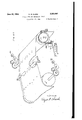
- Fig. 3A shows a penumatic valve with internal valve seat.
- Fig. 3B shows apneumatic valve with external valve seat.
- Fig. 4 shows a mechanical valve for the transfer of suction from one channel to another.
- Fig. 5 shows a method of shaping the perfora- .tions in the tape for the main code so that the record may be read back by the operator.
- Fig. 6A shows a translation chart for the device shown in Fig. 1A.
- Fig. 6B shows a. translation chart for the device shown in Fig. 1B.
- Fig. 6C shows a translation chart for the device shown in Fig. 1C.
- Fig. 6D shows a translation chart for the device shown in Fig. 1D.
- Fig. 6E shows a translation chart for the device shown in Fig. 1E.
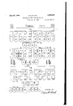
- Fig. 7A shows a permutation keyboard for perforating the main code.
- Fig. 7B shows letter code combinations for recording the main code on the tape.
- Fig. 7C shows numeral, punctuation, and miscellaneous code combinations for use in recording the main code on the tape.
- Fig. '1D shows an auxiliary keyboard for perforating ⁇ an auxiliary code at the side of the main record for causing certain changes to be marie in the main record.
- Fig. '7E shows a commercial typewriter keyboard.
- Fig. 8A shows the tape in place in a tape controlling device with means to advance the tape records in succession to the tape testing elements, also means for reversing the direction of movement of the tape as directed by the auxiliary perforations.
- Fig. 8B shows horizontal lines representing the main code record on a tape, while the small circles at the 'right represent auxiliary perforations for modifying the main code record as by mak-v ing an insertion.
- Fi'g. 9 shows a sequence control device as an alternative of the apparatus shown in Figs. 2A and 2B.
- Fig. 10 is a key for itting the main figures together.
- Fig. 1 1A shows the plan view of another sequence control device as an alternative of the apparatus shown in Figs. 2A and 2B.
- Fig. 11B shows an elevation of the sequence control device shown in Fig. 11A
- Fig. 11C shows the method of control for the start and stop bars for the sequence ,control device shown inFigs. 11A and 11B.
- Fig. 12 shows a sample of the details o1 the aanwas notchinao: the bars in the crossbar translator showninllig. 1.
- the first operation records dictation in code on a tape in a manner similar to the Ireland code printer as far as operation is concerned. However, instead of a record being produced in printed form it is produced as perforations in the tape with space reserved on one side of the tape for periorations representing corrections or changes.
- a tape controlling device is provided for reading the record and transferring it in code from the tape to the translating device.
- the translating device is built up of mechanical crossbars. One section is for translation of full spelling code symbols and another section for translation of 'symbols of phrasing and phonetic spelling. All power control for operating the various parts of the system is obtained from a suction supply system which operates bellows in a well known manner, as now used in player pianos and in the control of standard typewriters for producing a plurality of original copies.
- sequence mechanism comprises a plurality of valves mechanically operated by the vertical bars to control the printing by a standard typewriter by means of bellows in the printer operated by suction.
- the suction in the suction tank may be maintained approximately constant by means of a motor pump, and thesuction valves and bellows may be designed of ample size so that any form of typewriter may be used.
- the permutation keyboard shown in Fig. 7A may be operated in several ways, that is, a combination of keys may be operated to select a single character or a plurality of characters.
- It may also be operated to select a phrase at a single stroke, in which case one or more keys may be operated to select one or more characters for representing each word of the phrase.
- words used in phrasing may also be used separately in words translation; for example, the phrase of the may be transcribed in full from the symbol FL also the word OF may be written separately from the symbol F and the Word the may be written separately from the symbol T. Since words may be written with or without translation, or in phrases it may be considered as a triple function keyboard. Each key when depressed punches a hole in a tape passing through the device and advanced one step for each operation.
- the letters STKPWHR are to be operated by the fingers of the left hand and are known as left to right, for printing. This either'hand, and
- ⁇ keys to be operated by pushing the thumbs forinitial consonants.
- FRPBLGTSDS are the nal consovice.
- the keys are non-locking.
- Fig. 7B The letter combinations are shown in Fig. 7B.
- theletter F (initial) may be obtained by a combination of keys T and P operated simultaneously.
- the letter G is obtained by operating keys TKPW.
- the letters QU are obtained by keys KW. It is believed that the other key combinations may be readily seen from Fig. "IB. By this method of illustration all the combinations are shown at a glance and a simple method for study is provided. ⁇ Any word may be selected by spelling out from left to right.
- two space keys SP are provided, the one in the center to be operated by a downward stroke with a linger of the one adjacent to the vowel ward after a vowel key has been operated.
- the former is faster to operate and is used when there is an available finger.
- the word should is obtained with full spelling by operating the letters S and H by two ngers of the left hand; O and U by the thumbs, L and D by two ngers of the right hand. and the space key by moving the thumbs forward; this may all be recorded at a. single stroke.
- These letters require no translation, but a large percentage of the letters, however, 'will require translation.
- a word oi' as many as eight letters may be recorded with full spelling at a single stroke including the space; for example the word straight.”
- 'I'he letters, S, T and R are operated by three lingers of the le'ft hand, A with 'the thumb of the left hand and EU withthe thumb oi' the right hand (EU equals I).
- EU the thumb oi' the right hand
- a word may be recorded. It may be divided into one or more letters until it is spelled out so long as the letters read from left to right.
- the usual method is a stroke per syllable. A one syllable word, therefore, in most cases may be recorded in full spelling at a single stroke. There are some cases where two syllables may be recorded in full spelling at a single stroke. Due to keyboard assneas tape from which a period will be printed. The letter S (nal) together with the transfer bar (TB) will operate the carriage return (CR).
- a large percentage of the frequently used words may be recorded in this manner at a single stroke including the space.
- Fig. 7C 'Ihe miscellaneous keyboard characters or signs are shown in Fig. 7C. These characters are obtained by operating the corresponding letter keys or combination of keys simultaneously with the transfer bar TB.
- the letter R. (nal) when operated with the transfer f bar causes'a code record to be perforated in the 75 ⁇ V also is a simple method of showing all miscellaneous combinations, and is a convenient form for study.
- the part to be inserted is recorded on the tape at a point following the dictation already made.
- the tape controlling device will be directed to skip all printing between the punches and move to the point Where the insertion is recorded, and then to start the printing. After the insertion is printed the tape controlling device Will be directed to rotate the tape backward to the point where the printing was skipped, and the regular printing is resumed.
- An alternative plan for making corrections is for the attendant to perforate the tape in a manner that will stop the printing at a point where the correction is to be made and then type the correction in manually on the manual keyboard of the same typewriter. After the correction has been completed the regular printing can be resumed by the operation of a key. In each correction the attendant has the choice of which method should be used.
- a proof copy may show that certain combinations may have been operated in error.
- the attendant may by means of an auxiliary serts a new sheet and restarts the printing.
- a phrasing code record always consists of two or more letter combinations, while a phonetic spelling code record for a complete word may consist of one or more letter combinations.
- Code perforator (not shown) is similar to the one disclosed in my copending application where it is shown in Fig. 7F. As shown in that application it is arranged to ⁇ perforate either a clean cut hole or to produce embossings, with the perforator points shown in associated Fig. 1l. These points may furthermore be shaped as shown in Fig. 5 of the drawings attached hereto for the purpose of facilitating reading back by the operator without a template.
- the tape is first perforated by the operator in ⁇ the manner disclosed in my copending application by means of the code perforator shown in Fig. 7F of that case.
- the transcription attendant may then make any auxiliary perforations by means of an auxiliary keyboard, as indicated by the operator in pencil.
- the tape is then placed in the proper position in the tape reading or tape v controlling device shown in Fig. 8A of the presnt drawings. This provides means for transerring the record in code from the tape to the translating device, in a manner similar to thatused in the automatic control of pianos.
- air is admitted to a trip valve which applies suction gto a bellows which collapses due to the suction and supplies power for operation of the translator.
- the trip valve is shown in Fig. 3A and operates as follows: A diaphragm l is provided over the chamber 2 and separates it from a suction chamber 3 in the block 4. A bleeder passage 5 establishes communication between the diaphragm chamber 2 and suction chamber 3. A bellows (not shown) is attached to tube B, and has a spring connection to the bellows member y and suitably attached to a ilxed part of the frame the valve disc 1 is displaced downwardly. When to normally hold the bellows distended.
- Thevalve disc] has valve seats Il) to cooperate with the ports 6 and 8 for closing the suction passage and opening the port 6 to admit atmospheric pressure to the bellows at B when the valve 1 ascends from its downward position to establish communication between the chambers 3 and I2, the bellows is under suction influence and collapses against the urge of the spring.
- the suction chambers 2 are connected with suction supplied from a suction'tank and maintained in a well known manner by means of a motor, etc., through a conduit A.
- Each' of the bellows is provided with a link that is connected to a horizontal bar or any device which needs movement by power.
- the presence of atmospheric pressure in conduit c due to a tape perforation or to the opening of a valve causes diaphragm l to bulge upwardly by reason of the vacuum in chamber 3, the surface of that of disc valve 1 and the bleeder passage 5 being small compared to the opening at conduit c. This causes valve 1 to ascend upward to close port 6 and open port 8. Thereupon a vacuum is extended through the port 8 to collapse the bellows through conduit B.
- conduit c When conduit c is closed either by the tape or a valve a vacuum is again established in the diaphragm chamber 2 by reason of its communication with the suction passage 3 through bleeder passage 5.
- the valve disc 1 is returned to its initia1 position chamber l2 so that the bellows distends or expands with the aid of the spring.
- valve disc 1 The normal position of valve disc 1 is down when conduit A has access to suction and conduit c is closed which means that no suction is applied at conduit B.
- conduit c When conduit c is opened the valve 1 moves up to close off the atmosphere at passage 6 and connects suction to conduit B from the source at conduit A.
- the valve In case the valve is to be made slow in operating thebleeder outlet at a; is provided so that when suction is applied at conduit A time is required to draw the air from chamber 3, but when the valve 1 starts upward passage Il is openedv so that the full suction is supplied to the bellows as soon as valve 1 closes passage 6. If the valve is not to be made slow in operating the small outlet at c: is omitted. This is called an inside valve and will be illustrated as an oblong in the drawings.
- valve shown in Fig. 3B is an outside valve and is represented by an oblong with a knob on the outside. Its operation in general is similar to that shown in Fig. 3A.
- the valve is normally down with c closed so that when suction is applied at A it is immediately cut through to D.
- the bleed at 5 applies suction slowly to extract the air from chamber 2 to hold the valve down.
- tube i3 is provided with a bleed at When the valve is down passage I4 is closed by valve 1.
- chamber 2 has access to air the diaphragm being larger than of transferring suction from .vided in each row and.
- valves in Figs. 3A and 3B may be combined, that is they may be connected in multiple by connecting suction to A in both valves and connecting conduits c together. but leaving conduits B and D individual. This provides means D-to B, by the operation of both valves.
- the locking feature is required it may be provided as shown in Fig. 3B which serves to cause both valves to be locking.
- the slow operate feature may be provided as shown in Fig. 3A but does not ailect the operation of the valve shown in Fig.- 3B. To restore the locking valves thesuction may be temporarily removed or suction may. be appliedat chamber 2 by a tube not shown.
- 'I'he type of valve shown in Fig. 4 consists of a metallic cylinder I which revolves in a hollow cylinder 2 when operated by a movement of the actuating member C.
- a normal path from A to D is provided by path 3.
- the path from A to D is cut oil and instead 'one is provided from A to B.
- the valve is used as a cut oilvalve the cylinder I is moved a less amount such as 60 degrees, where no outlet is provided.
- the cylinder returns to normal by means of a spring not shown.
- 'I'his valve will be represented as a circle in the drawings. l v
- the tape reading device has a plurality of tubes T which terminate immediately below the tape in a certain deinite order corresponding to the keys on the perforator keyboard, and the other end of each terminates in an associated valve and bellow as described under Fig. 3A.
- the bellows corresponding to certain perforations operate and the others do not operate because' the tape closes the tubes where no perforation appears.
- Any vowel bar being operated such as E in this case operates the common bar VB to the right which in turn ,by means of a wire over pulleys: operates VWLV as per Fig. l so that it now points to the full spelling translator.
- a common tape perforation is proto allow the horizontal rods etc. time to get set, the correspondingfbellows CB is made slow in operating. This is accomplished by means of a restriction at x which retards the action.
- the load on FSST may be split up into sections if necessary.y Bars T. H and E only in this case are allowed to take their alternate positions because they are the only ones which have a clear mechanical path to move and the others are blocked mechanically.
- Each bar has two positions for each cross point.
- Each vertical bar has a notch opposite each horizontal -bar when it is in the normal position, which is to allow a free movement of the horizontal bars to take a setting.
- Each vertical bar has metal below each horizontal bar to make a test aiter the setting to determine mether or not it has a clear path.
- the translation cuttings appear on the horizontal rods. and may have metal or a notch opposite a vertical bar either when it is normal or when it is oil normal. For example.
- the horizontal bar T has metal in the normal position to block the vertical bar T and when it is moved off normal to the right this is cleared and no may be designed either other metal is placed to block vertical bar T and since horizontal bar H does not block T it is free to move upward.
- the action is similar in the case-of bar H.
- the nrst E vertical bar is the only one
- the vertical bars operate they also op erate associated valves TV, HV and EV, also' associated group valves GI, Gl, and GIU, by means oi wires not shown.
- the individual valves are individual to the letters T, H and E.
- Fig. 12 shows a notching the horizontal or code bars and the method of translation.
- the vertical or character bars are not shown notched. as described above, but are arranged to move inward toward the plane p'f the horizontal bars, instead of longitudinally as shown in Fig. 1.
- the translator bars In practice the translator way. With the translator bars arranged as in Fig.
- the symbol identifying means may be integral with the bars of one or the other sets of translator bars and may preferably be in the form of projections and cuts along an edge of the individual bars.
- the projections are formed on the receiving code bars reference may be had to the Patent No. 1,745,633 issued to Morton et al. on Feb. 4, 1930, and for an example of an arrangement in which the projections are formed on the printing controlling character bars reference may be had to Patent No. 1,623,809 issued to Pfannenstiehl on April 5, 192.7.
- the group valves are each common to an arbitrary group o! letters arranged so that no two letters in any one group will be required from the record of any one row on the tape. They are made common to provide apparatus economy.
- Eachv group valve in operating expands its associated TMB as shown in full for G3 in which the letter T appears.
- the group valves normally point straight through horizontally until they are operated by a vertical bar when they point upward to a letter valve.
- the action is similar but it is not shown in full. This causes each TMB to expand and be ready to collapse when suction is applied.
- STPB which controls the start valve STPV is made slow to operate by means of restriction
- FSST operates it opens valve V which allows suction from ST to extract the air slowly from STPB because of restriction at, and after a predetermined interval it operates s'rPV.
- suction through Gl, G2 and G3, TV and TRV to TB.
- Thelatter collapses and operates the typewriter key T to print the letter T.
- suction is also applied through GI, G2 and TV to 'I'MB to return G3 and TV to normal. is made slow in operating by means of a restriction not shown, to allow time for the letter T to be printed before G3 operates to transfer the suction for the next letter.
- TMB returns G3, TV and associated vertical bar T to normal against the associated spring S.
- Valve G3 now points through the series to the next outlet which is G5 to print H in a similar manner and return vertical bar H to normal.
- the letter E is printed and the associated apparatus returned to normal.
- the suction may now be applied to SPBI through SPV which operates to record the space on the typewriter. SPV returns to normal to extend suction through ELV and TABV which normally points to RLB, Fig.
- the bar IN sets I in G2, which is the first I available from the'left. N in G3 4and the first from left PSPV for supplying the space.
- the bar LETTER sets L in G9, E in GII), T in GII, D, Tin GI2, E in Gis, R in Gld and the next PSPV.
- the printing is similar to that described above except for the delay by valve D inserted between GII and GIZ. Its operation after the ilrst letter T is the same as for any group valve except that it does not print a character. The delay is introduced to allow the typewriter to function properly for the rst letter T and completely release before the next Operation of the letter T is started.
- each wire contains a spring (not shown) the -total strength of all of which is less than of the one designated S associated with the INbar. Since when TMIB operates, each valve restores to normal to cut through, the individual spring allows the valve associated with the character being printed' to return to normal without releasing any other valve associated with the bar IN.
- the load on PPST may be divided as required.
- Phonetc spelling The general action is similar to the phrasing except that only one word is involved instead of two or more. For illustration assume the word believe which' with full spelling would require two strokes because of the lack of combination IE.
- the abbreviation is BL-V and its code is PWHR-BLG.
- the horizontal bars are set from the tape according to the code. The cuttings on these code bars allow the vertical bar BELIEVE to operate. No other bar has a clear path toY operate.
- This vertical bar now sets the individual and group valves as follows: B in GI. E in G1, L in G9, I in GI2, E in G I3, V in GIS, E in GIS, and space SPV. v ⁇ The printing action is similar to the operation described above.
- the suction' is extended to HYPB which operates the HYP key to print a hyphen. Simultaneously receives suction to operate slowly to allow time for the printing of the hyphen.
- TRB therefore operates VWLV in all cases the same as if a vowel had been operated in full spelling.
- the translator is then set in a similar manner to that in which it would be set if the associated letter has been used in full spelling in conjunction with key VS.
- the group valves are set in a similar manner and the action of printing is similar except TRV transfers to the associated special bar instead of-a letter bar.
- TRB operates TRV to transfer the suction path from TB to 1"B.
- SPVL which locks to -latch L5
- TABB whichoperates the tabular key to move the carriage to the paragraph position. This also unlocks PARB and it returns to normal and releasesv TABV and extends the suction to RLB to release the apparatus as before.
- period, space, begin capital, question, carriage return and paragraph may be recorded on one row on the tape such as period and space; period, space and begin capital; period, space, begin capital and carriage return; period, begin capital, carriage return and paragraph. Similar combinations including the comma or question mark may also be used.
- Carriage return with period and space may be operated with something else such .as period and space, the combination being TB, SP, R, S.
- the action is similar to the printing of RS and space except 'IRB which is operated from TB transfers the suction from R tothe period which is printed, the space is recorded ln the regular way and TRB transfers the suction from S to the CR bellows which operates EN and it locks. After the period and space are recordedthe carriage return takes place similar to that previously described.
- Numerals The numerals are assigned similar to the assignment on the code printer as shown on Fig. 7C. For example to print 4 the I'B and H keys are operated. VThe translator attempts to print the letter H but since TRV has been operated it now points to the 4$B and it 'is operated instead to print the character 4. Other numerals may be printed in a similar manner.
- the words may always be written in the same manner, for example, in case the word begins with a capital, the latter record may be recorded in advance and then the word written as usual.
- the iirst letter will print as a capital and shift back to the lower case and the other letters will print as small letters.
- the translator starts as if it were going to print the letter B but since al1 TRV valves are operated BCB is operated instead and locks by means of latch L2, and the translator returns to'normal, except the shift key which is held operated.
- the translator returns to'normal, except the shift key which is held operated.
- RBCB operates slowly through BCV to allow for the printing of the first character, after which it releases BCB and BCV and the shift key RBCB is made slow operate by means of a restriction at Since all valves TV were originally operated by BCB (not shown in full) to prevent the operation of any TMB until the carriage had fully released from the upper case and completely settled, BCB releases all valves TV and the first TMB which has a path nowoperates to allow time ior the carriage to settle after which the rest of the characters print in the usual way.
- the combination may be recorded in advance by the operation of E and TB.
- This operates a bellows (not shown) and it locks in a manner similar to BCB and operates the shift key but not valves TV. This remains locked until the operator unlocks it and in the meantime the translator causes the printing of al1 capitals.
- U, TB This operates an unlocking bellows similar to the printing of the letter U" except TB causes it to be transferred to the unlock bellows (not shown) instead, which is similar to RBCB.
- Punctuation tion mark will be printed. Similarly other ⁇ combinations may be obtained.
- Double letters This action is similar to the action for double T in the word letter.
- the valve D between G and G8 is set.
- the valve between GII and Gl2 is set.
- the valve at the left of Gil is set.
- the TMB associated merely introduces a time delay between the letters to allow the printer to function properly.
- the secondary perforator provides keys A', B and C' for the smaller changes as follows:
- An alternative plan is to punch a stop combination and insert small changes manually.
- code bars AB' and C' are set according to the tape record and the bars cut according to a translation chart shown in Fig. 6E, to cause the proper vertical bar to be selected according to the code.
- the individual valve In the case of split syllables due to a lack of keyboard combinations the individual valve is operated through GH because of additional perforatlons made by the attendant.
- GI'ICV intercepts the suction and prevents it from being extended to CR where a hyphen would be inserted in a split syllable.
- begin capital In the case of begin capital, the record is: perforated opposite the preceding row in which the begin capital is to be recorded. After the regular record of the row has been printed the record of begin capital is stored in the translator. When the following row is printed it is modified to print the first letter as a capital and the rest in small letters.
- the record for stop printing is perforated opposite the last row that is to lbe printed.
- SPBC After the regular translation and printing has taken place SPBC, not shown, is operated through GI'I and it operates SPVC which locks under the con- 7 trol of key RL and removes suction from the translator. to stop the printing action, and is under control of the key RL by the attendant.
- SPBC is operated through GI'I and it operates SPVC which locks under the con- 7 trol of key RL and removes suction from the translator. to stop the printing action, and is under control of the key RL by the attendant.
- SPVC which locks under the con- 7 trol of key RL and removes suction from the translator. to stop the printing action, and is under control of the key RL by the attendant.
- the other miscellaneous combinations are similar to those described above.
- Fig. 8D shows the necessary perforations for making one cancellation and an insertion instead thereof.
- a perforation in row SF operates SFB and it operates a rotary device SFC which causes a lug such as L to close contact C to prepare a circuit for motor M l.
- SFB is made slow in operating to allow CB to open contact CB2 to prevent the motor starting prematurely.
- the tape advances one step and the apparatus releases in the usual way including SFB.
- the motor Ml is now started by contacts C and CB2 to rotate the tape forward at a comparatively slow speed
- SFB operates to advance SF to release contact C to stop the motor and release SFBV.
- the motor in stopping releases RLV to make the translator effective to print the insert I in the regular manner.
- a perforation in row SB is encountered to operate SBB and it operates SBC to cause a lug such as LI to close contact CI to prepare a circuit for the motor as before. It also operates SBBV to make SFB ineffective.
- the record for the last row of the insert has been completed CB in releasing in the regular way closes contact CB2 to start the motor M2 to rotate the tape backward.
- SW2 removes ratchet R to allow the tape to move freely and it operates RLV to' render the translator ineffective.
- FIG. 9 shows the alternative for G3.
- the group is to remain idle when the printing action takes place CV is cut through from CVG2 to PSPV, and the suction is blocked at G31 and TV and other similar valves.
- the letter T is to be printed at G3 translator bar T is operated to open tubes C to TV and C to CVG3. The regular operation up to the point where suction is applied to thev tube .from CVG! is similarv to that previously described.
- valves of the type shown in Fig. 4 may be replaced as iollows: STIV by an inside valve,
- Seconol alternative plan A second alternative arrangement for storing of the translated record and for control of the printing sequence is shown in Figs. 11A, 11B and 11C.
- a plurality of storing bars SB are arranged in close proximity for eooperation with a motor driven element PCB which in revolving reacts with those storing bars in succession which have been set in the storing position by the translator.
- the bars in Fig. 11A are also set with the inner end of the bars tilted upward about pivot P.
- nothing corresponds tilted upward to block the printing control bar PCB which is indirectly under the control of motorM through gear G and is loosely coupled by to the motor and the motor stops.
- PCB By means of the spring in SH, PCB quickly moves over certain bars which are not set and strikes the T bar which is set.
- PCB should be constructed of any suitable light weight material so the hammering action will not be so great when striking the bars which are set. This causes the inner part of the T bar as shown in Fig. 11A to move to the right on pivot P, against springs.
- Pivot P isdesigned so the bar SB can move its lever end out of the plane of the paper to get in the path of PCB and it can also turn in the plane of the paper to open the tubes to trip the valves.l This opens the tubes designated print T and time T. The former in opening trips valve TV, Fig. 11B, to allow suction at S to be applied to TB through TRV.
- Dust remover Since a suction tank is maintained, if desired a pair of suction slots (not shown) may be added above and below the tape at a point before it passes the tape reading device. This is to remove lint and dust to prevent it from entering the valves.
- Magnet and relay control It is the general plan in this system that provides the economy rather than the suction control.
- the suction valves throughout could easily be replaced by magnets and relays without departing from the-spirit of the invention.
Landscapes
- Document Processing Apparatus (AREA)
Description
June 20, 1944. E CLARK 2,351,663
TRANSLATING AND RECORDING DEVICE Fiied Feb. 27, 1941 9 sheets-sheet 1` FWRC GHPNBMKLCGXSVLTYS DESH June 20, 1944. E H, CLARKl 2,351,663
TRANSLATING AND RECORDING DEVICE Filed Feb. 27, 1941 9 Sheets-Sheet 2 June 20, 1944. E. H. CLARK TRANSLATING AND RECORDING DEVICE Filed Feb. 27, 1941 9 Sheets-Sheet 3 0 un@ 94010404.9104 .v0 n o o o. o
EE. 4 man D u a .man 1l.
nu U l .1
Sd BDVdS /NVENTOR nu "U 4G40 i n o ANWXdl.
June 20,` 1944. E` H, CLARK 2,351,663y
I TRANSLATING AND RECORDING DEVICE Filed Feb. 27, 1941 v 9 sheets-sheet 4 u 9 iL .w
/NVENTOR QSI m; s
Sui.
' June 20, 1944. E. H. CLARK 2,351,663
TRANSLATING AND RECORDING DEVICE Filed Feb. 27, 1941 9 Sheets-Sheer?I 5 UC ADDRESS FIG 7H TA T P H VS F P L P M L 'L' T l D N v c Y E` K X P6 S1' GT sY GTS CK FBG 8K I'RBG NK PBI.
June 20, 1944. E H, CLARK 2,351,663
TRANSLATING AND RECORDING DEVICE Filed Feb. 27, 1941 9 Sheets-Sheet 6 w MvH xcaa EAEIU CHOI T K P W H R F' R B T Gl G7. G3 F/QQD U va D' eea A" B C I FIG.6E
INVENTOR June 20, 1944. E H, CLARK 2,351,663
' TRANSLATING AND RECORDING DEVICE Filed Feb. 27, 1941 9 Sheets-Sheet 7 INVENTF June 20, 1944.
TRA
m `es of! hl LIIII cn m .OLD
Filed Feb. 27, 1941 9 Sheets-Sheet 8 June 20, 1944. E. H. CLARK TRANSLATING AND RECORDING DEVICE4 9 Sheets-Sheet 9 Filed Feb. 27, 1941 LorcKlNcjCso) Ll Patented June 20, 1944 UNITED STATES PATENT OFFICE y 2,351,663 l 'rmsmrmd AND RECORDING DEVICE Edgar H. Clark, Kew Gardens, N. Y.
Application February 27, 1941, 'serial No. 380,819
(c1. 19t-2o) 20 Claims.
This invention relates to translating and recording systems and more particularly to systems oi this kind in which a code message is reproduced as a printed record in page form.
By my invention disclosed in U. S. Patent No. 1,913,831, issued on June 13, 1933, I provided an arrangement for setting up the message on a permutation keyboard which passed the characters of the message in code form to a translating device which in turn controlled the operations of a standard automatic typewriter. The code was based on a system of full spelling.
In my copending application Ser. No. 160,294, filed on Aug. 21, 1937, issued as Patent No. 2,283,- 538 on May 19, 1942, I have disclosed a system in which the message is recorded upon a tape in code form and the tape is passed through a code testing device which impresses the successive code records upon the translating system for translation and subsequent printing. To permit high speed dictation the message on the tape may appear in codes of different kinds. Thus certain parts of the message may be recorded by a fullspelling code, other parts hy a phonetic spelling code,` and still others in an abbreviated code representing phrases or formulae. In that system I have also made provision for the proper printing of the message with such changes or corrections as are directed by the tape record. The full spelling code is similar to that being used in a' commercial code printer, such as that disclosed in U. S. Patent No. 1,280,743 issued to W. S. Ireland on Oct. 8, 1918. In the preferred form of my invention, as disclosed in my said copendng application, the entire system is based upon operations of electromagnetic relays and electric circuits controlled'originally by a row of testing contacts in the code testing device and ultimately operating the printer keys and function levers in the recording printer by means of electromagnets.
An object of the present invention is to provide a translating and recording system capable of performing the same functions as that disclosed in my copending application referred to but of a simpler and less expensive construction.
It is a further object to provide a system of this kind which will readily permit changes in the translation and almost unlimited additions to the code, and which thus will be adaptable for use in various specific fields.
It is a more specific object to reduce the number of relays and circuits in such a system by substituting simple cooperating mechanical elements therefor.
It is a still further object to provide a system of this kind which is more easily manufactured and which is more easily understood by manufacturers and repair men accustomed to mechanical devices such as typewriters, adding machines, etc.
It is a particular object to provide a mechanical translator which is capable of simultaneous translation of two o r more code symbols.
It is a principal object to provide a simple and rugged system which is extremely reliable in operation.
It is an important object to simplify the operation of such a system and particularly to avoid successive translations of any particular code record. i
In accordance with the invention the system may be generally operated by any convenient type'of relay or power device. but certain portions thereof such as the different translator sections are preferably built up of Amechanical elements, permutated and coordinated in any desirable manner, and the elements receive settings by means of the power devices in accordance with the impressed symbols and in turnyupon translation, control Vother power devices for advancing the translated intelligence to the printer.
In the preferred form of the invention, such as that illustrated in the 'attached drawings and described in detail hereinafter the relays or power devices are of the pneumatic type controlled over air passages and in turn controlling mechanical devices or other pneumatic relays.
In the preferred form the translating device has 'a translating field of crossbars, of which the primary or code receiving bars are notched in accordance with a predetermined scheme dependent upon the codes and their translation;
,these code receiving bars or units are set into alternate positions, so that a plurality of them cooperate to present selective combinations of notches to secondary or character setting bars of the translator whereby any one or more of the latter may be simultaneously selected for setting or operation and thus effectively represent the translation of the received symbols.
In my copending application, referred to above, I provided a system in which a primary or syllable translator receives the coded record of one syllable at a time, translates the code and transfers the translated syllable to a printing device one letter at a time by means of a sequence control arrangement. In the case of phonetic spelling and phrasing the coded record for a plurality of syllables is received by a secondary translator where it is translated and stored usually as a plurality of syllables, which however still are coded in accordance' with the basic full-spelling code. 'I'he record is then passed one syllable at a time to the primary translator in the fullspelling code and each syllable is translated and Printed in a manner similar tothat described above.
'I'he reason for this double translation, nrst by the secondary and then by the primary translatorfin the case oi phonetic spelling and phrasing is that such translation ina practical and speedy system involves a large number of code combinations, and to provide the necessary relay equipment for direct translation, as in the case of full spelling, would complicate the system undesirably and would result in a prohibitive first y the present invention, the use of crossbars in the translators results in such a decided simplification that it is feasible and in fact advantageous to use direct translation of even quite extensive phrases, thereby further simplifying the system and its operations.
Thus in accordance with a feature of the invention a phrasing code record is translated in its entirety in one operation and is stored full length and fully spelled for printing of one character at a time by the typewriter. The sequence control arrangement by which the phrase is stored for printing therefore is made of suflicient capacity to store phrases of reasonable lengths and to permit of ample freedom in the choice of word combinations.
In accordance with a. further feature of the invention the arrangement of the phrasing translator and sequence control arrangement just referred to permits ready addition or substitution of phrases to suit particular business requirements. Thus additional secondary bars may readily be added in the phrasing translator to respond to new assigned codes and corresponding settings of the primary bars. The new bars are furthermore readily cross connected to corresponding letter valves at suitable group valves in the sequence control arrangement.
Other features of the invention will be apparent from the following drawings, description and appended claims.
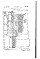
Drawings Fig. 1 shows aI mechanical crossbar translatingl crossbar translating device for the iinal consonants.
Fig. 1D shows a portion of the mechanical crossbar translating device for phrasing and phonetic spelling.
Fig. 1E shows a portion of the Amechanical crossbar translating device for the smaller changes in the main record.
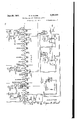
Figs. 2A and 2B show a device. for storing of of the printing of a word or syllable which begins with a capital.
Fig. 2D shows apparatus for the control of a motor and the printing for the larger changes in the main code such as cancellations and insertions.
Fig. 2E shows apparatus for the control of the typewriter as to carriage return when the end of a line has been reached.
Fig. 2F shows apparatus for the testing and insertion of a, hyphen as required when a word is split at the end of a line.
Fig. 2G shows apparatus for the control of paragraphing or tabulation in the printing.
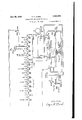
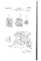
Fig. 3A shows a penumatic valve with internal valve seat.
Fig. 3B shows apneumatic valve with external valve seat.
Fig. 4 shows a mechanical valve for the transfer of suction from one channel to another.
Fig. 5 shows a method of shaping the perfora- .tions in the tape for the main code so that the record may be read back by the operator.
Fig. 6A shows a translation chart for the device shown in Fig. 1A.
Fig. 6B shows a. translation chart for the device shown in Fig. 1B.
Fig. 6C shows a translation chart for the device shown in Fig. 1C.
Fig. 6D shows a translation chart for the device shown in Fig. 1D.
Fig. 6E shows a translation chart for the device shown in Fig. 1E.
Fig. 7A shows a permutation keyboard for perforating the main code.
Fig. 7B shows letter code combinations for recording the main code on the tape.
Fig. 7C shows numeral, punctuation, and miscellaneous code combinations for use in recording the main code on the tape.
Fig. '1D shows an auxiliary keyboard for perforating` an auxiliary code at the side of the main record for causing certain changes to be marie in the main record.
Fig. '7E shows a commercial typewriter keyboard.
Fig. 8A shows the tape in place in a tape controlling device with means to advance the tape records in succession to the tape testing elements, also means for reversing the direction of movement of the tape as directed by the auxiliary perforations.
Fig. 8B shows horizontal lines representing the main code record on a tape, while the small circles at the 'right represent auxiliary perforations for modifying the main code record as by mak-v ing an insertion.
Fi'g. 9 shows a sequence control device as an alternative of the apparatus shown in Figs. 2A and 2B.
Fig. 10 is a key for itting the main figures together.
Fig. 1 1A shows the plan view of another sequence control device as an alternative of the apparatus shown in Figs. 2A and 2B.
Fig. 11B shows an elevation of the sequence control device shown in Fig. 11A,
Fig. 11C shows the method of control for the start and stop bars for the sequence ,control device shown inFigs. 11A and 11B.
Fig. 12 shows a sample of the details o1 the aanwas notchinao: the bars in the crossbar translator showninllig. 1.
l Designations AC alternating current BC begin capital BCV begin capital valve BCB begin capital bellows FSST full spelling start translation G gear GICV etc. group one common valve etc. GS-I group 3 inside GS-O group 3 outside HYPB hyphen bellows i HYPTB hyphen timing bellows HYPV hyphen valve IBS insert back space IC insert comma IP insert period IPR insert paragraph LC line counter M motor P pivot PCB printing control bar PARB paragraph bellows PCRV phrase carriage return valve PPST phrase and phonetic start translation PSPV phrase space valve RBCB release begin capital bellows RL release RLB release bellows RLV release valve SB space bellows SBB skip backward bellows SBBV skip backward bellows valve SBC skip backward control SFB skip forward bellows SFC skip forward control SFBV skip forward bellows valve SH spring housing SO slow operate SP stop printing SPB space bellows SPBC stop printing bellows control SPV space valve SPVC stop printing valve control SPVL space valve lock SR slow release ST suction tank STK start key STPB set phrase bellows STPV start printing valve S'ITV start translator valve SV suction valve SW switch- TA tape advance TABB tabular bellows TABV tabular valve TB etc. letter T bellows etc.
TMB timing bellows TMV time valve TRB transfer bellows 'I'RCV transfer C valve TRV transfer valve TV T valve UC upper case VB vowel bar VS vowel substitute VWLV vowel valve General description This description is of the specic embodiment shown in the drawings and is intended not to limit the scope of the invention but, rather to facilitate the understanding of the details which follow.
The first operation records dictation in code on a tape in a manner similar to the Ireland code printer as far as operation is concerned. However, instead of a record being produced in printed form it is produced as perforations in the tape with space reserved on one side of the tape for periorations representing corrections or changes. x
A tape controlling device is provided for reading the record and transferring it in code from the tape to the translating device.
The translating device is built up of mechanical crossbars. One section is for translation of full spelling code symbols and another section for translation of 'symbols of phrasing and phonetic spelling. All power control for operating the various parts of the system is obtained from a suction supply system which operates bellows in a well known manner, as now used in player pianos and in the control of standard typewriters for producing a plurality of original copies.
The successive portions of the record on the tape. are transferred to the translator by means of bellows which are tripped from perforations in the tape and cause the setting of the horizontal or code receiving bars, after which the vertical or character selection bars are set according to the translation, that is, those vertical bars which have a mechanically clear path established by the notching combinations of the horizontal bars, are moved to their alternate positions. The decoded portion of the record is then transferred to a sequence control mechanism of mechanical storing devices and in the proper relation, sequence mechanism comprises a plurality of valves mechanically operated by the vertical bars to control the printing by a standard typewriter by means of bellows in the printer operated by suction.
The suction in the suction tank may be maintained approximately constant by means of a motor pump, and thesuction valves and bellows may be designed of ample size so that any form of typewriter may be used.
The permutation keyboard shown in Fig. 7A may be operated in several ways, that is, a combination of keys may be operated to select a single character or a plurality of characters.
It may also be operated to select a phrase at a single stroke, in which case one or more keys may be operated to select one or more characters for representing each word of the phrase.
Most words used in phrasing may also be used separately in words translation; for example, the phrase of the may be transcribed in full from the symbol FL also the word OF may be written separately from the symbol F and the Word the may be written separately from the symbol T. Since words may be written with or without translation, or in phrases it may be considered as a triple function keyboard. Each key when depressed punches a hole in a tape passing through the device and advanced one step for each operation. x
The letters STKPWHR are to be operated by the fingers of the left hand and are known as left to right, for printing. This either'hand, and
`keys to be operated by pushing the thumbs forinitial consonants. The letters sondare the vowels and may be operated with the thumbs.
' 'Ihe letters FRPBLGTSDS are the nal consovice. The keys are non-locking.
The letter combinations are shown in Fig. 7B. For example theletter F (initial) may be obtained by a combination of keys T and P operated simultaneously. The letter G is obtained by operating keys TKPW. The letters QU are obtained by keys KW. It is believed that the other key combinations may be readily seen from Fig. "IB. By this method of illustration all the combinations are shown at a glance and a simple method for study is provided.` Any word may be selected by spelling out from left to right.
For convenience in operating, two space keys SP are provided, the one in the center to be operated by a downward stroke with a linger of the one adjacent to the vowel ward after a vowel key has been operated. The former is faster to operate and is used when there is an available finger.-
For illustration, the word should" is obtained with full spelling by operating the letters S and H by two ngers of the left hand; O and U by the thumbs, L and D by two ngers of the right hand. and the space key by moving the thumbs forward; this may all be recorded at a. single stroke. These letters require no translation, but a large percentage of the letters, however, 'will require translation.
A word oi' as many as eight letters may be recorded with full spelling at a single stroke including the space; for example the word straight." 'I'he letters, S, T and R are operated by three lingers of the le'ft hand, A with 'the thumb of the left hand and EU withthe thumb oi' the right hand (EU equals I). The letters F,
P, L, T (in which F, P, L equals GH) are operated with the lingers oi' the right hand.
There are various ways in which a word may be recorded. It may be divided into one or more letters until it is spelled out so long as the letters read from left to right. The usual method is a stroke per syllable. A one syllable word, therefore, in most cases may be recorded in full spelling at a single stroke. There are some cases where two syllables may be recorded in full spelling at a single stroke. Due to keyboard assneas tape from which a period will be printed. The letter S (nal) together with the transfer bar (TB) will operate the carriage return (CR).
, combinations will be evident from Fig. 7C. This limitations there are some one syllable words which cannot be recorded at a single stroke in full spelling. In the development of the invention words in the latter class which are most frequently used will be assigned codes in phonetic spelling, and'then may be recorded at a single stroke.
A large percentage of the frequently used words may be recorded in this manner at a single stroke including the space.
'Ihe miscellaneous keyboard characters or signs are shown in Fig. 7C. These characters are obtained by operating the corresponding letter keys or combination of keys simultaneously with the transfer bar TB. For example, the letter R. (nal) when operated with the transfer f bar causes'a code record to be perforated in the 75 `Valso is a simple method of showing all miscellaneous combinations, and is a convenient form for study.
Tape changes and reading back During dictation the operator indicates changes if any, in pencil as with the Ireland code printers. After the dictation has been completed the typing attendant makes corresponding changes if required by punching side of the tape with an auxiliary Improvements are provided in by shaping the perforations similar to the corresponding letters as shown in Fig. 5. 'Ihis allows the operator to read back substantially the same as with the code printers, and without resorting to any printing apparatus.
For small detail changes such as the addition of punctuation, space, back space, begin capital or paragraph, rows are provided in the tape in which one hole or a. combination of holes may be punched where a correction is desired. The code punched automatically selects the particular detail that should be added. In case it becomes necessary to change a comma to a period or any change of a similar nature, the comma may be cancelled by stickers and a period may be inserted by punching the proper combination on the side of the tape.-
perforator.
In case of large changes such as cancellations.
or insertions, other rows are provided in which holes may be punched in the proper combinations to accomplish any desired change.
Thus in the case of an insertion, the part to be inserted is recorded on the tape at a point following the dictation already made. By making the proper punches in the tape, the tape controlling device will be directed to skip all printing between the punches and move to the point Where the insertion is recorded, and then to start the printing. After the insertion is printed the tape controlling device Will be directed to rotate the tape backward to the point where the printing was skipped, and the regular printing is resumed.
An alternative plan for making corrections is for the attendant to perforate the tape in a manner that will stop the printing at a point where the correction is to be made and then type the correction in manually on the manual keyboard of the same typewriter. After the correction has been completed the regular printing can be resumed by the operation of a key. In each correction the attendant has the choice of which method should be used.
A proof copy may show that certain combinations may have been operated in error. In this -case the attendant may by means of an auxiliary serts a new sheet and restarts the printing.
holes on the reading back* .l is provided inthe block l above the valve body Phrasn und 'phonetic spelling Provision is made for the above to a certain degree and the disclosed arrangement should be considered as illustrative only, and not as a complete engineering job. The codes may be assigned in substantially the same way as for code printers. except for one difference, namely. that no vowels are to be assigned as the presence and absence 'of vowels is used as a discriminating feature to avoid the need for operating a special key for discrimination. Since in full spelling every syllable, or nearly everysyllable, contains a vowel, and the phrasing or phonetic code records are made without the operation of a vowel key, the translator can immediately discriminate between the two types of codes and get set accordingly. A phrasing code record always consists of two or more letter combinations, while a phonetic spelling code record for a complete word may consist of one or more letter combinations.
Address Since the selection of an address or formula and its inclusion in the printing from an auxiliary machine is shown in my copending application it Code perforator The code perforator (not shown) is similar to the one disclosed in my copending application where it is shown in Fig. 7F. As shown in that application it is arranged to`perforate either a clean cut hole or to produce embossings, with the perforator points shown in associated Fig. 1l. These points may furthermore be shaped as shown in Fig. 5 of the drawings attached hereto for the purpose of facilitating reading back by the operator without a template.
' Detail description The tape is first perforated by the operator in `the manner disclosed in my copending application by means of the code perforator shown in Fig. 7F of that case. The transcription attendant may then make any auxiliary perforations by means of an auxiliary keyboard, as indicated by the operator in pencil. The tape is then placed in the proper position in the tape reading or tape v controlling device shown in Fig. 8A of the presnt drawings. This provides means for transerring the record in code from the tape to the translating device, in a manner similar to thatused in the automatic control of pianos. Thus when a perforation in the tape is encountered air is admitted to a trip valve which applies suction gto a bellows which collapses due to the suction and supplies power for operation of the translator. The trip valve is shown in Fig. 3A and operates as follows: A diaphragm l is provided over the chamber 2 and separates it from a suction chamber 3 in the block 4. A bleeder passage 5 establishes communication between the diaphragm chamber 2 and suction chamber 3. A bellows (not shown) is attached to tube B, and has a spring connection to the bellows member y and suitably attached to a ilxed part of the frame the valve disc 1 is displaced downwardly. When to normally hold the bellows distended. A port shown in the drawings and air is admitted into Vis opened a rush of air in chamber 2 causes to provide access to the atmosphere, 'there being a valve disc 1 in the suction chamber to control the ports 8 and 8 for opening or closing responsive to the action of the diaphragm I that cooperates with a rod 9 extending axially from the valve disc 1. Thevalve disc] has valve seats Il) to cooperate with the ports 6 and 8 for closing the suction passage and opening the port 6 to admit atmospheric pressure to the bellows at B when the valve 1 ascends from its downward position to establish communication between the chambers 3 and I2, the bellows is under suction influence and collapses against the urge of the spring. The suction chambers 2 are connected with suction supplied from a suction'tank and maintained in a well known manner by means of a motor, etc., through a conduit A. Each' of the bellows is provided with a link that is connected to a horizontal bar or any device which needs movement by power. The presence of atmospheric pressure in conduit c due to a tape perforation or to the opening of a valve causes diaphragm l to bulge upwardly by reason of the vacuum in chamber 3, the surface of that of disc valve 1 and the bleeder passage 5 being small compared to the opening at conduit c. This causes valve 1 to ascend upward to close port 6 and open port 8. Thereupon a vacuum is extended through the port 8 to collapse the bellows through conduit B. When conduit c is closed either by the tape or a valve a vacuum is again established in the diaphragm chamber 2 by reason of its communication with the suction passage 3 through bleeder passage 5. Thus the valve disc 1 is returned to its initia1 position chamber l2 so that the bellows distends or expands with the aid of the spring.
The normal position of valve disc 1 is down when conduit A has access to suction and conduit c is closed which means that no suction is applied at conduit B. When conduit c is opened the valve 1 moves up to close off the atmosphere at passage 6 and connects suction to conduit B from the source at conduit A. In case the valve is to be made slow in operating thebleeder outlet at a; is provided so that when suction is applied at conduit A time is required to draw the air from chamber 3, but when the valve 1 starts upward passage Il is openedv so that the full suction is supplied to the bellows as soon as valve 1 closes passage 6. If the valve is not to be made slow in operating the small outlet at c: is omitted. This is called an inside valve and will be illustrated as an oblong in the drawings.
The type of valve shown in Fig. 3B is an outside valve and is represented by an oblong with a knob on the outside. Its operation in general is similar to that shown in Fig. 3A. The valve is normally down with c closed so that when suction is applied at A it is immediately cut through to D. The bleed at 5 applies suction slowly to extract the air from chamber 2 to hold the valve down. As in Fig. 3A when c the valve to move upward and cut off the suction to outlet D. In case it is desirable to make the valve locking, that is to remain operated after c has 'again been closed, tube i3 is provided with a bleed at When the valve is down passage I4 is closed by valve 1. When the valve has been operated chamber 2 has access to air the diaphragm being larger than of transferring suction from .vided in each row and.
through bleed :c so that ,when c is closed the valve remains operated. If the valve is to be nonlocking tube I3 may be omitted or plugged. The valves in Figs. 3A and 3B may be combined, that is they may be connected in multiple by connecting suction to A in both valves and connecting conduits c together. but leaving conduits B and D individual. This provides means D-to B, by the operation of both valves. If the locking feature is required it may be provided as shown in Fig. 3B which serves to cause both valves to be locking. The slow operate feature may be provided as shown in Fig. 3A but does not ailect the operation of the valve shown in Fig.- 3B. To restore the locking valves thesuction may be temporarily removed or suction may. be appliedat chamber 2 by a tube not shown.
'I'he type of valve shown in Fig. 4 consists of a metallic cylinder I which revolves in a hollow cylinder 2 when operated by a movement of the actuating member C. A normal path from A to D is provided by path 3. When cylinder I is revolved 120 degrees by the movement oi' C the path from A to D is cut oil and instead 'one is provided from A to B. When the valve is used as a cut oilvalve the cylinder I is moved a less amount such as 60 degrees, where no outlet is provided. When power is removed from C the cylinder returns to normal by means of a spring not shown. 'I'his valve will be represented as a circle in the drawings. l v
The tape reading device has a plurality of tubes T which terminate immediately below the tape in a certain deinite order corresponding to the keys on the perforator keyboard, and the other end of each terminates in an associated valve and bellow as described under Fig. 3A. The bellows corresponding to certain perforations operate and the others do not operate because' the tape closes the tubes where no perforation appears.
Let it be assumed that the word THE is to 'be printed with full spelling as it is shownin full on the drawings including the space. When the tape is placed in the proper position the attendant may start the printing by the operation of STK vwhich locks. 'I'his operates S'I'I'V which applies suction to the translator from ST through RLV and SPVC all valves normally pointing in the direction of the arrows. They are similar to the valve shown in Fig. 4 which is arranged to transfer suction from one outlet to another. Since a transfer is not need in these cases the outlet to be transferred to may be plugged and the valve used for cutting off the suction. 'I'his connects suction to TB, HB, etc. The tape being perforated for THE and space now oper'- ates corresponding bellows to directly set the associated horizontal bars by moving them to their alternate positions. moved longitudinally, but they may be designed to be rotated if desired. There is no bar however for the space as it requires no translation.. 'I'he SPV' is set directly by SPB which is operated because of the space perforation. The rest of the action will be described later.
Any vowel bar being operated such as E in this case operates the common bar VB to the right which in turn ,by means of a wire over pulleys: operates VWLV as per Fig. l so that it now points to the full spelling translator. To start the action a common tape perforation is proto allow the horizontal rods etc. time to get set, the correspondingfbellows CB is made slow in operating. This is accomplished by means of a restriction at x which retards the action. After CB 'operates it operates SV to apply suction through VWLV to FSST which collapses tofdraw the associated bar upward by means of a wire over a pulley. This tries to draw all vertical bars upward by means of springs S. The load on FSST may be split up into sections if necessary.y Bars T. H and E only in this case are allowed to take their alternate positions because they are the only ones which have a clear mechanical path to move and the others are blocked mechanically.
l This translation is shown in Fig. 6A for T and H and Fig. 6B for E. Each bar has two positions for each cross point. Each vertical bar has a notch opposite each horizontal -bar when it is in the normal position, which is to allow a free movement of the horizontal bars to take a setting. Each vertical bar has metal below each horizontal bar to make a test aiter the setting to determine mether or not it has a clear path. The translation cuttings appear on the horizontal rods. and may have metal or a notch opposite a vertical bar either when it is normal or when it is oil normal. For example. the horizontal bar T has metal in the normal position to block the vertical bar T and when it is moved off normal to the right this is cleared and no may be designed either other metal is placed to block vertical bar T and since horizontal bar H does not block T it is free to move upward. The action is similar in the case-of bar H. In the case ot the E translation the nrst E vertical bar is the only one When the vertical bars operate they also op erate associated valves TV, HV and EV, also' associated group valves GI, Gl, and GIU, by means oi wires not shown. The individual valves are individual to the letters T, H and E.
Fig. 12 shows a notching the horizontal or code bars and the method of translation. For the sake of clarity in the drawings, the vertical or character bars are not shown notched. as described above, but are arranged to move inward toward the plane p'f the horizontal bars, instead of longitudinally as shown in Fig. 1. In practice the translator way. With the translator bars arranged as in Fig.
1 2 a. lug on the code bar B in the normal posi- They lare shown as being character bar S has a clear path for moving 1nward. The setting of code bar S in this group has no eiect on the rest of the translation. Lug I on code -bar K in the normal position blocks the character bar K from moving inward but it is cleared when the code bar K is moved to the right. Lug I on primary code bar W blocks character bar W until the code bar W is moved to the right. It both the primary code bars K and W are moved to their alternate positions secondary bar KI is blocked by lug I on primary bar W and secondary bar W is blocked by lug 3 -on primary bar K. Secondary bars Q and U now have a clear path to move downward so that the code of KW will be translated'into QU. S
It should be understood that the selective coperspective of the method oi' operation between the primary or code bars and the secondary or character bars at their intersection points may be carriedv out by different means without a departure from the spiritl of the invention. Thus the symboll identifying means whereby the code is translated in the crossbar frame may be separate elements placed between the intersecting portions of the. two sets oi bars,
as illustrated in the Patent No. 1,545,581 issued to Chaplin on July 14, 1925. Or the symbol identifying means may be integral with the bars of one or the other sets of translator bars and may preferably be in the form of projections and cuts along an edge of the individual bars. For an example of an arrangement in which the projections are formed on the receiving code bars reference may be had to the Patent No. 1,745,633 issued to Morton et al. on Feb. 4, 1930, and for an example of an arrangement in which the projections are formed on the printing controlling character bars reference may be had to Patent No. 1,623,809 issued to Pfannenstiehl on April 5, 192.7.
The last mentioned itself to the addition of new phrases within the original capacity of the system, because it will be possible to add new character bars with proper cuttings within the length of the smooth code bars and to connect the new bars to appropriate printing valves associated with the sequence control means.
The group valves are each common to an arbitrary group o! letters arranged so that no two letters in any one group will be required from the record of any one row on the tape. They are made common to provide apparatus economy. Eachv group valve in operating expands its associated TMB as shown in full for G3 in which the letter T appears. The group valves normally point straight through horizontally until they are operated by a vertical bar when they point upward to a letter valve. For the letters H and E and also the space, the action is similar but it is not shown in full. This causes each TMB to expand and be ready to collapse when suction is applied. We now have the record in decoded form stored in the series of valves ready for` printing. In order to allow time for this action to take place STPB which controls the start valve STPV is made slow to operate by means of restriction When FSST operates it opens valve V which allows suction from ST to extract the air slowly from STPB because of restriction at, and after a predetermined interval it operates s'rPV. 'This applies suction through Gl, G2 and G3, TV and TRV to TB. Thelatter collapses and operates the typewriter key T to print the letter T. Simultaneously with this action. suction is also applied through GI, G2 and TV to 'I'MB to return G3 and TV to normal. is made slow in operating by means of a restriction not shown, to allow time for the letter T to be printed before G3 operates to transfer the suction for the next letter. TMB returns G3, TV and associated vertical bar T to normal against the associated spring S. Valve G3 now points through the series to the next outlet which is G5 to print H in a similar manner and return vertical bar H to normal. Similarly the letter E is printed and the associated apparatus returned to normal. The suction may now be applied to SPBI through SPV which operates to record the space on the typewriter. SPV returns to normal to extend suction through ELV and TABV which normally points to RLB, Fig.
arrangement readily lends.
` This operates ratchet R to of TA and simultaneously 8A, which operates. engage the next tooth operates RLV by a wire to remove the suction from all apparatus, so that it may return to normal. When RLB returns to normal TA advances one step for tape advance, and the record on the next row of the tape is transferred to the apparatus. RLB is made slow in releasing to allow all apparatus to release.
Various combinations may be translated and typed in a manner similar to those just described and all regular typing is accomplished in this manner. The following table shows a list of combinations which may be used with this system. They may best be checked in units, that is, all the initial consonants, then the vowels, then the nal consonants.
This list is in addition to the single letter combinations shown in Fig. 7B.
Initial consonants is written in code.
is operated after SV, instead of FSS'I as'previously described.- 'I'he translation is made and the vertical bars set as shown in Fig. 6D. TPH provides a clear path for the IN bar, R a path for YOUR and L a path for LETTER. No other vertical bars have a path. Any of these words may be recorded individually by its individual code. These bars now set the individual and group-valves across the sequence control device. The bar IN sets I in G2, which is the first I available from the'left. N in G3 4and the first from left PSPV for supplying the space. The bar YOUR sets Y in G4, O in G5, U in G6, R in G7 and the next PSPV. The bar LETTER sets L in G9, E in GII), T in GII, D, Tin GI2, E in Gis, R in Gld and the next PSPV. The printing is similar to that described above except for the delay by valve D inserted between GII and GIZ. Its operation after the ilrst letter T is the same as for any group valve except that it does not print a character. The delay is introduced to allow the typewriter to function properly for the rst letter T and completely release before the next Operation of the letter T is started.
Another diilerence is that in setting the valves, for example for the word IN and space each wire contains a spring (not shown) the -total strength of all of which is less than of the one designated S associated with the INbar. Since when TMIB operates, each valve restores to normal to cut through, the individual spring allows the valve associated with the character being printed' to return to normal without releasing any other valve associated with the bar IN.
The load on PPST may be divided as required.
Similarly other phrasesy listed may be translated and printed.
Phonetc spelling The general action is similar to the phrasing except that only one word is involved instead of two or more. For illustration assume the word believe which' with full spelling would require two strokes because of the lack of combination IE. The abbreviation is BL-V and its code is PWHR-BLG. The horizontal bars are set from the tape according to the code. The cuttings on these code bars allow the vertical bar BELIEVE to operate. No other bar has a clear path toY operate. This vertical bar now sets the individual and group valves as follows: B in GI. E in G1, L in G9, I in GI2, E in G I3, V in GIS, E in GIS, and space SPV. v`The printing action is similar to the operation described above.
The following is a list netic spelling used in this of phrasing and phoembodiment. This is a small sample but by a similar process phrasing y Y and phonetic spelling may be added indefinitely at a very small cost, is first developed.
that is, when the translator Phrasing Phonetic spelling to you TY- between -BT inyourletter N-RL about ot the -FT believe BL-V to the T-T in N- y to your T-R our -R we have been W-FB otter -L inthe N-T of -F we have W-F the -T in your N-R to T- yourletter -RL we W- to have T-F have F- to have been T-FB build B-L you Y- Gs, Ga and Gle. If we astuces y.automatic 'carriage return The system is arranged to provide an auto matic advance at the action to the contrary operator, the device will word and insert a hyphen and then start a new line. In order to prevent hyphens being inserted in undesired places, it is necessary for the operator to split words in syllables insofar as possible. There are some rare cases, however, where this is not possible due to certain keyboard limitations. Provision is made to cancelthis effect and will be described later.
If during the printing of a syllable in full spelling the carriage reaches the end of the line it operates ELV which locks to latch L. After the completion of the printing of the syllable in the usual way the series valves are vextended to ELV which because it has been operated is pointing If it is operated and locked to SPB has been operated the suchas been taken by the automatically split the to release ELV normal. This transfers the suction to RLB and the release takes place as previously described.
In case the SPB had not operated SPVL, the suction' is extended to HYPB which operates the HYP key to print a hyphen. Simultaneously receives suction to operate slowly to allow time for the printing of the hyphen.
is made slow in operating by means of a restriction at az. When it operates it remains operatedand transfers the suction to operate the carriage return after which the apparatus returns to normal as described above.
In the case of phrasing the action is different, no provision being made for inserting a hyphen since the words of a phrase will never be split into syllables. The phrase, however, is split into words. Provision is made for carriage return at the end of any word in the phrase as PCRV after assume the phrase "in your letter" as described above, and the carriage reaches the end of the line while the word IN is' being printed ELV operates. have been moved ol normal to the left by space PI, P2 and P3, they are in position to engage lugs L3 if drawn downward. This happens when through the series. After the space for the word IN has been operated the suction is extended through the rst PCRV to CRC to return the carriage after which ELV is restored to normal as previously'described. The other valves PGRV are also connected to CRC but no leak may be .Special` combinations All special combinations shown in Fig. 7C are end of a line, and if no Since lugs L4 operated in conjunction with TB. This operates TRB which operates all valves TRV to 1transfer the suction from the regular letter bellows to the ones indicated in Fig. 7C. Since the translation is -similar in each individual case, to the associated letter, the i'ull spelling translator is to be used. TRB therefore operates VWLV in all cases the same as if a vowel had been operated in full spelling. The translator is then set in a similar manner to that in which it would be set if the associated letter has been used in full spelling in conjunction with key VS. The group valves are set in a similar manner and the action of printing is similar except TRV transfers to the associated special bar instead of-a letter bar. For example TRB operates TRV to transfer the suction path from TB to 1"B. When the space bellows operated, yit operated SPVL which locks to -latch L5, and remains operated after the space through TABV to operate TABB whichoperates the tabular key to move the carriage to the paragraph position. This also unlocks PARB and it returns to normal and releasesv TABV and extends the suction to RLB to release the apparatus as before. Y
Similar to the above any appropriate combination of period, space, begin capital, question, carriage return and paragraph may be recorded on one row on the tape such as period and space; period, space and begin capital; period, space, begin capital and carriage return; period, begin capital, carriage return and paragraph. Similar combinations including the comma or question mark may also be used.
Carriage return with period and space The carriage return may be operated with something else such .as period and space, the combination being TB, SP, R, S. The action is similar to the printing of RS and space except 'IRB which is operated from TB transfers the suction from R tothe period which is printed, the space is recorded ln the regular way and TRB transfers the suction from S to the CR bellows which operates EN and it locks. After the period and space are recordedthe carriage return takes place similar to that previously described. v
Numerals The numerals are assigned similar to the assignment on the code printer as shown on Fig. 7C. For example to print 4 the I'B and H keys are operated. VThe translator attempts to print the letter H but since TRV has been operated it now points to the 4$B and it 'is operated instead to print the character 4. Other numerals may be printed in a similar manner.
i Miscellaneous rthe upper case combination. For example, the
Begin capital In order to keep the operating uniform it is very desirable that the words may always be written in the same manner, for example, in case the word begins with a capital, the latter record may be recorded in advance and then the word written as usual. The iirst letter will print as a capital and shift back to the lower case and the other letters will print as small letters. When the combination for begin capital is encountered,
that is B, TB, the translator starts as if it were going to print the letter B but since al1 TRV valves are operated BCB is operated instead and locks by means of latch L2, and the translator returns to'normal, except the shift key which is held operated. When the next word, syllable or phrase is encountered the first letter is printed as a capital because the shift key is operated. RBCB operates slowly through BCV to allow for the printing of the first character, after which it releases BCB and BCV and the shift key RBCB is made slow operate by means of a restriction at Since all valves TV were originally operated by BCB (not shown in full) to prevent the operation of any TMB until the carriage had fully released from the upper case and completely settled, BCB releases all valves TV and the first TMB which has a path nowoperates to allow time ior the carriage to settle after which the rest of the characters print in the usual way.
All capitals For writing with all capitals, the combination may be recorded in advance by the operation of E and TB. This operates a bellows (not shown) and it locks in a manner similar to BCB and operates the shift key but not valves TV. This remains locked until the operator unlocks it and in the meantime the translator causes the printing of al1 capitals. To unlock the combination it is necessary to operate U, TB. This operates an unlocking bellows similar to the printing of the letter U" except TB causes it to be transferred to the unlock bellows (not shown) instead, which is similar to RBCB.
Punctuation tion mark will be printed. Similarly other` combinations may be obtained.
Double letters This action is similar to the action for double T in the word letter. In case double E or O is required the valve D between G and G8 is set. For double T or L the valve between GII and Gl2 is set. For .double S the valve at the left of Gil is set. The TMB associated merely introduces a time delay between the letters to allow the printer to function properly.
Changes in the tape record Operators are usually very accurate on this type of keyboard and it is believed that very A dictator or operator.
returned leaves the CR record still there.
few corrections will'be necessary. All operators, however, will make some mistakes and provision is made for changes. Some changes will be necessary because of the dictator such as cancellations and insertions, and provision is made to not impose any limitations on the part of the The operator in taking dictation may indicate any changes in pencil as is done at present. An attendant later makes any necessary changes on a secondary `perforator which is similar to the primary recording device shown in the copending application Fig. 7F, the keyboard of which is shown in Fig. 7D. The secondary machine is arranged for. punching holes at one edge of the tape to cause the changes in control to be made automatically.
The secondary perforator provides keys A', B and C' for the smaller changes as follows:
A=Begin capital B'=Insert back space C=Stop printing A'B'=Insert paragraph AC=Insert comma B'C=Insert period A'B'C=Cancel split syllable The above combinations are not limited to three rows as four rows would furnish fifteen combinations and five rows would furnish thirty-one combinations.
An alternative plan is to punch a stop combination and insert small changes manually.
To select any of the above combinations code bars AB' and C' are set according to the tape record and the bars cut according to a translation chart shown in Fig. 6E, to cause the proper vertical bar to be selected according to the code. After it is set it operates the corresponding individual valve and the associated Gil. If a period has been selected it is inserted at the end of the regular printing in a manner similar to any character. In the case of split syllables due to a lack of keyboard combinations the individual valve is operated through GH because of additional perforatlons made by the attendant. GI'ICV intercepts the suction and prevents it from being extended to CR where a hyphen would be inserted in a split syllable. The suction is extended instead to a bellows for CSS, not shown in full, but which operates pawl R for tape advance and causes the release of the translator similar to the operation of RLB for that purpose. 'I'he fact that the carriage was not record on the next row of the tape which is the last part of the word is now recorded on the translator and printed in the regular manner after which the carriage is returned in the usual manner. Y
In the case of begin capital, the record is: perforated opposite the preceding row in which the begin capital is to be recorded. After the regular record of the row has been printed the record of begin capital is stored in the translator. When the following row is printed it is modified to print the first letter as a capital and the rest in small letters.
The record for stop printing is perforated opposite the last row that is to lbe printed. After the regular translation and printing has taken place SPBC, not shown, is operated through GI'I and it operates SPVC which locks under the con- 7 trol of key RL and removes suction from the translator. to stop the printing action, and is under control of the key RL by the attendant. The other miscellaneous combinations are similar to those described above.
The
Cancellations and insertions Fig. 8D shows the necessary perforations for making one cancellation and an insertion instead thereof. While the record of the last row of the upper printing section is being taken a perforation in row SF operates SFB and it operates a rotary device SFC which causes a lug such as L to close contact C to prepare a circuit for motor M l. SFB is made slow in operating to allow CB to open contact CB2 to prevent the motor starting prematurely. When the record for the above row 'has been printed the tape advances one step and the apparatus releases in the usual way including SFB. The motor Ml is now started by contacts C and CB2 to rotate the tape forward at a comparatively slow speed,
'and SFB operates to advance SF to release contact C to stop the motor and release SFBV. The motor in stopping releases RLV to make the translator effective to print the insert I in the regular manner. When the record for the last row in the insert is being printed a perforation in row SB is encountered to operate SBB and it operates SBC to cause a lug such as LI to close contact CI to prepare a circuit for the motor as before. It also operates SBBV to make SFB ineffective. When the record for the last row of the insert has been completed CB in releasing in the regular way closes contact CB2 to start the motor M2 to rotate the tape backward. SW2 removes ratchet R to allow the tape to move freely and it operates RLV to' render the translator ineffective. Since the only apparatus now effective is SBB the tape rotates backward until a perforation in row SB is encountered at which time SBB again Aoperates to rotate SBC one step, which opens contact CI to stop the motor and release SBBV. The motor now stops and releases RLV to make the translator effective at the row where the printing is to be resumed, which now takes place in the usual way to the point where the printing is to stop. As the record for the last row is being taken a perforation in the stop row or C' is encountered after the regular translation and printing have taken place and SPBC is operated through Gll and operates SPVC which locks under the control of key RL and removes suction from the translator to stop the printing action until the attendant is ready to start the action again.
End of page tooth in the rotating device and when ELV releases LC steps one step under the control of the associated spring. Any number of steps may be provided and arranged so that when the end of the page is reached, lug L2 engages lever L3 to operate SPVC to stop the printing. This calls the attention of the attendant who may now insert a new page, and restart the printing.
First alternative plan Inasmuch as the type of valves shown in Figs. 3A and 3B are less subject to leaks due to wear than the type shown in Fig. 4, an alternative plan is outlined which makes use of the valves shown in Figs. 3A and 3B. Fig. 9 shows the alternative for G3. In case the group is to remain idle when the printing action takes place CV is cut through from CVG2 to PSPV, and the suction is blocked at G31 and TV and other similar valves. In case the letter T is to be printed at G3 translator bar T is operated to open tubes C to TV and C to CVG3. The regular operation up to the point where suction is applied to thev tube .from CVG! is similarv to that previously described. When suction is applied at point A it causes the immediate operation of CVG3 because tube C has been opened by the translator bar T. Since tube C from G30 and GI-I is closed they do not operate vbut Gl-O is cut through to point A at TV. TV immediately operates because theC tube is open. This applies suction at points A of TRV! and TRVZ. Since TRB has not been operated tube C to TRVI is open and the one at TRVZ is closed. In this case TRVI operates slowly to print the letter T and to momentarily open TCV. This causes the operation of G3-O and G3-I the former cutting off suction to the apparatus above and the latter cutting the suction through to PSPV. Since these two valves are made locking the cutting through is maintained until the release`of the apparatus at the end of the printing operations for that particular record, when suction is removed. The translator bar Tin this plan is not restored to normal, so that CVG3 remains operated until the apparatus is all released. In case the numeral 21s to be printed TRB would operate when the record is taken from the tape. This operates TRCV which opens the C tube to TRVZ and closes the C tube to TRVl and hence causes the operation of 2B instead of TB.
Other valves of the type shown in Fig. 4 may be replaced as iollows: STIV by an inside valve,
-BLV-inside, VWVL-inside and outside, SV-inside,
STPV-inside, ELV-inside and outside, HYPVin side and outside, TABV-inside and outside. BCV- inside, SFBV-outside, SBBV-outside, PCRV-inside and outside, SPVC-outslde locking, SPVL- inside and outside locking, PCPV-inside and outside.
Seconol alternative plan A second alternative arrangement for storing of the translated record and for control of the printing sequence is shown in Figs. 11A, 11B and 11C. In this arrangement a plurality of storing bars SB are arranged in close proximity for eooperation with a motor driven element PCB which in revolving reacts with those storing bars in succession which have been set in the storing position by the translator. As soon as the vertical character setting bars in Fig. 1 are set as described above, the bars in Fig. 11A are also set with the inner end of the bars tilted upward about pivot P. In this plan nothing corresponds tilted upward to block the printing control bar PCB which is indirectly under the control of motorM through gear G and is loosely coupled by to the motor and the motor stops. Let it be assumed that the spring is wound up and the printi ying bars such as T are set for printing. When the printing isto start STPB in Fig. 2A is operated as previously described and tilts the inner end of the start bar downward from the position shown'in Fig. 11C. It also allows the inner end of the stop bar to move upward by means of spring S. I
By means of the spring in SH, PCB quickly moves over certain bars which are not set and strikes the T bar which is set. PCB should be constructed of any suitable light weight material so the hammering action will not be so great when striking the bars which are set. This causes the inner part of the T bar as shown in Fig. 11A to move to the right on pivot P, against springs. Pivot P isdesigned so the bar SB can move its lever end out of the plane of the paper to get in the path of PCB and it can also turn in the plane of the paper to open the tubes to trip the valves.l This opens the tubes designated print T and time T. The former in opening trips valve TV, Fig. 11B, to allow suction at S to be applied to TB through TRV. 'I'his causesTB to operate and operate the typewriter key T andcause the printing of the character thereof. Simultaneously with this operation the opening of the tube time T causes 'I'MV to operate slowly to allow time for the printing. After a predetermined interval suction at S is applied to TMB and it operates to restore bar T to normal against spring S in Fig. 1A. By a similar process PCB quickly moves to the next bar which is set and causes the corresponding character to be printed and the bar to be restored to normal, and so on until all the characters in this particular record are printed, after which PCB moves to the stop bar which now has the inner end tilted upward. This causes the inner end of the stop bar to move to the right on pivot P and open tube RLV. This causes a trip valve (not shown) similar to TV to apply suction to RLB, Fig. 8A. and release the apparatus and advance the tape as previously described. When the suction is removed by the `operation. of RIB, STPB releases and allows spring S which is attached to the start bar, and which is stronger than spring S, which is attached to the stop bar, to simultaneously move contact referred to above closes and starts theA the inner ends of the start and stop bars up and down respectively. This allows PCB to pass the stop bar and move to the start bar, ready forthe next action.
After the spring is partly unwound the motor motor to keep the spring wound up as required.
Dust remover Since a suction tank is maintained, if desired a pair of suction slots (not shown) may be added above and below the tape at a point before it passes the tape reading device. This is to remove lint and dust to prevent it from entering the valves.
Magnet and relay control It is the general plan in this system that provides the economy rather than the suction control. The suction valves throughout could easily be replaced by magnets and relays without departing from the-spirit of the invention. The
Priority Applications (1)
| Application Number | Priority Date | Filing Date | Title |
|---|---|---|---|
| US380819A US2351663A (en) | 1941-02-27 | 1941-02-27 | Translating and recording device |
Applications Claiming Priority (1)
| Application Number | Priority Date | Filing Date | Title |
|---|---|---|---|
| US380819A US2351663A (en) | 1941-02-27 | 1941-02-27 | Translating and recording device |
Publications (1)
| Publication Number | Publication Date |
|---|---|
| US2351663A true US2351663A (en) | 1944-06-20 |
Family
ID=23502563
Family Applications (1)
| Application Number | Title | Priority Date | Filing Date |
|---|---|---|---|
| US380819A Expired - Lifetime US2351663A (en) | 1941-02-27 | 1941-02-27 | Translating and recording device |
Country Status (1)
| Country | Link |
|---|---|
| US (1) | US2351663A (en) |
Cited By (5)
| Publication number | Priority date | Publication date | Assignee | Title |
|---|---|---|---|---|
| US2873837A (en) * | 1955-10-17 | 1959-02-17 | Jr Edgar H Clark | Automatic code translating systems |
| US2932375A (en) * | 1958-05-27 | 1960-04-12 | Royal Mcbee Corp | Decoding device |
| US2960570A (en) * | 1958-11-12 | 1960-11-15 | Edgar H Clark Jr | Automatic code translating systems |
| US3011618A (en) * | 1958-05-27 | 1961-12-05 | Royal Mcbee Corp | Decoding arrangement |
| US3228509A (en) * | 1965-03-31 | 1966-01-11 | Royal Typewriter Co Inc | Pneumatically operated data processing system |
-
1941
- 1941-02-27 US US380819A patent/US2351663A/en not_active Expired - Lifetime
Cited By (5)
| Publication number | Priority date | Publication date | Assignee | Title |
|---|---|---|---|---|
| US2873837A (en) * | 1955-10-17 | 1959-02-17 | Jr Edgar H Clark | Automatic code translating systems |
| US2932375A (en) * | 1958-05-27 | 1960-04-12 | Royal Mcbee Corp | Decoding device |
| US3011618A (en) * | 1958-05-27 | 1961-12-05 | Royal Mcbee Corp | Decoding arrangement |
| US2960570A (en) * | 1958-11-12 | 1960-11-15 | Edgar H Clark Jr | Automatic code translating systems |
| US3228509A (en) * | 1965-03-31 | 1966-01-11 | Royal Typewriter Co Inc | Pneumatically operated data processing system |
Similar Documents
| Publication | Publication Date | Title |
|---|---|---|
| US2346268A (en) | Record controlled perforating apparatus | |
| US2950800A (en) | Ideographic type composing machine | |
| US4527919A (en) | Method for the composition of texts in Arabic letters and composition device | |
| US2351663A (en) | Translating and recording device | |
| US2116732A (en) | Coding and decoding machine | |
| US2283538A (en) | Translating and recording device | |
| US1913831A (en) | Translating and recording device | |
| US2859276A (en) | Apparatus for key operated mechanisms | |
| USRE21042E (en) | potts | |
| USRE20330E (en) | Keyboard mechanism for telegraph | |
| US1863098A (en) | Apparatus for computing statistical data | |
| US2031017A (en) | Keyboard | |
| US2865487A (en) | Record controlled printing or writing machines | |
| US2873837A (en) | Automatic code translating systems | |
| GB562278A (en) | Improvements in or relating to key-controlled printing and perforating mechanism | |
| GB754003A (en) | Justifier for typewriters | |
| US4687353A (en) | Automatic format, mode control and code conversion for data processing and printing apparatus | |
| US1827362A (en) | Printing telegraph system | |
| US1839402A (en) | Apparatus for transferring data from perforated records | |
| US2352952A (en) | Code converter | |
| US3194493A (en) | Apparatus for effecting alternate operation of the shift and unshift keys of a tape perforating machine | |
| US2704595A (en) | ackell | |
| US2390664A (en) | Tabulation control system | |
| US3228509A (en) | Pneumatically operated data processing system | |
| US2960570A (en) | Automatic code translating systems |